User Manual
Page 2
Motherboard GA-X79-UD5 Oct. 28, 2011 Motherboard GA-X79-UD5 Oct. 28, 2011
Motherboard GA-X79-UD5 Oct. 28, 2011 Motherboard GA-X79-UD5 Oct. 28, 2011
User Manual
Page 3
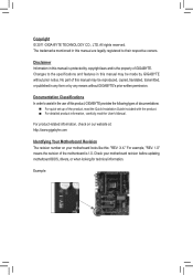
... to their respective owners. Example: Disclaimer Information in this manual may be made by GIGABYTE without GIGABYTE's prior written permission. No part of GIGABYTE. Copyright © 2011 GIGA-BYTE TECHNOLOGY CO., LTD. For example, "REV: 1.0" means the revision of the motherboard is the property of this : "REV: X.X." For product-related information, check on our...
... to their respective owners. Example: Disclaimer Information in this manual may be made by GIGABYTE without GIGABYTE's prior written permission. No part of GIGABYTE. Copyright © 2011 GIGA-BYTE TECHNOLOGY CO., LTD. For example, "REV: 1.0" means the revision of the motherboard is the property of this : "REV: X.X." For product-related information, check on our...
User Manual
Page 4
Table of Contents Box Contents...6 Optional Items...6 GA-X79-UD5 Motherboard Layout 7 GA-X79-UD5 Motherboard Block Diagram 8 Chapter 1 Hardware Installation 9 1-1 Installation Precautions 9 1-2 Product Specifications 10 1-3 Installing the CPU and CPU Cooler 13 1-3-1 Installing the CPU 13 1-3-2 Installing the CPU Cooler ...
Table of Contents Box Contents...6 Optional Items...6 GA-X79-UD5 Motherboard Layout 7 GA-X79-UD5 Motherboard Block Diagram 8 Chapter 1 Hardware Installation 9 1-1 Installation Precautions 9 1-2 Product Specifications 10 1-3 Installing the CPU and CPU Cooler 13 1-3-1 Installing the CPU 13 1-3-2 Installing the CPU Cooler ...
User Manual
Page 6
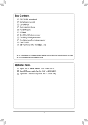
... 2-port USB 2.0 bracket (Part No. 12CR1-1UB030-5*R) 2-port SATA power cable (Part No. 12CF1-2SERPW-0*R) 2-port IEEE 1394a bracket (Part No. 12CF1-1IE008-0*R) - 6 - Box Contents GA-X79-UD5 motherboard Motherboard driver disk User's Manual Quick Installation Guide Four SATA cables I/O Shield One 2-Way SLI bridge connector One 3-Way SLI bridge connector One 2-Way CrossFireX bridge...
... 2-port USB 2.0 bracket (Part No. 12CR1-1UB030-5*R) 2-port SATA power cable (Part No. 12CF1-2SERPW-0*R) 2-port IEEE 1394a bracket (Part No. 12CF1-1IE008-0*R) - 6 - Box Contents GA-X79-UD5 motherboard Motherboard driver disk User's Manual Quick Installation Guide Four SATA cables I/O Shield One 2-Way SLI bridge connector One 3-Way SLI bridge connector One 2-Way CrossFireX bridge...
User Manual
Page 7
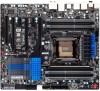
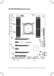
GA-X79-UD5 Motherboard Layout KB_MS_USB HS SYS_FAN2 USB_1394_ESATA USB_ESATAMarvell 88SE9172 R_USB30 USB_LAN AUDIO Fresco FL1009 DDR3_4 DDR3_8 DDR3_2 DDR3_6 ATX_12V_2X4 CPU_FAN LGA2011 DDR3_5 DDR3_1 DDR3_7 DDR3_3 SYS_FAN1 ATX PW_SW F_USB30 20 31 Intel GbE LAN PCIEX16_1 PCIEX1_1 BAT CODEC PCIEX8 VIA VT6308 PCIEX1_2 Fresco FL1009 GA-X79-UD5 Intel® X79 SATA3 4 5 PCIEX16_2 iTE IT8728 PCI F_AUDIO F_1394 TPM SPDIF_O SYS_FAN4 Marvell 88SE9172 GSATA3 F_USB3 F_USB2 F_USB1 Marvell 88SE9172 CLR_CMOS B_BIOS RST_SW M_BIOS SYS_FAN3 F_PANEL SATA2 6 7 8 9 - 7 -
GA-X79-UD5 Motherboard Layout KB_MS_USB HS SYS_FAN2 USB_1394_ESATA USB_ESATAMarvell 88SE9172 R_USB30 USB_LAN AUDIO Fresco FL1009 DDR3_4 DDR3_8 DDR3_2 DDR3_6 ATX_12V_2X4 CPU_FAN LGA2011 DDR3_5 DDR3_1 DDR3_7 DDR3_3 SYS_FAN1 ATX PW_SW F_USB30 20 31 Intel GbE LAN PCIEX16_1 PCIEX1_1 BAT CODEC PCIEX8 VIA VT6308 PCIEX1_2 Fresco FL1009 GA-X79-UD5 Intel® X79 SATA3 4 5 PCIEX16_2 iTE IT8728 PCI F_AUDIO F_1394 TPM SPDIF_O SYS_FAN4 Marvell 88SE9172 GSATA3 F_USB3 F_USB2 F_USB1 Marvell 88SE9172 CLR_CMOS B_BIOS RST_SW M_BIOS SYS_FAN3 F_PANEL SATA2 6 7 8 9 - 7 -
User Manual
Page 8
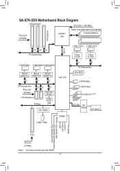
GA-X79-UD5 Motherboard Block Diagram 2 PCI Express x16 CPU CLK+/- (100 MHz) PCIe CLK (100 MHz) LGA2011 CPU DDR3 2133/1866/1600/1333/1066 MHz 4 Channel Memory 1 PCI ... Bus PCIe CLK (100 MHz) x1 x1 x1 Intel GbE LAN phy 2 PCI Express x1 RJ45 PCI Bus LAN VIA VT6308 2 IEEE 1394a Intel® X79 CODEC 2 USB 3.0/2.0 2 USB 3.0/2.0 Fresco FL1009 Fresco FL1009 x1 x1 PCI Express Bus Dual BIOS 2 SATA 6Gb/s 4 SATA 3Gb/s 14 USB 2.0/1.1(Note) LPC Bus iTE IT8728...
GA-X79-UD5 Motherboard Block Diagram 2 PCI Express x16 CPU CLK+/- (100 MHz) PCIe CLK (100 MHz) LGA2011 CPU DDR3 2133/1866/1600/1333/1066 MHz 4 Channel Memory 1 PCI ... Bus PCIe CLK (100 MHz) x1 x1 x1 Intel GbE LAN phy 2 PCI Express x1 RJ45 PCI Bus LAN VIA VT6308 2 IEEE 1394a Intel® X79 CODEC 2 USB 3.0/2.0 2 USB 3.0/2.0 Fresco FL1009 Fresco FL1009 x1 x1 PCI Express Bus Dual BIOS 2 SATA 6Gb/s 4 SATA 3Gb/s 14 USB 2.0/1.1(Note) LPC Bus iTE IT8728...
User Manual
Page 9
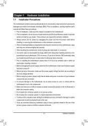
... ponents such as a result of electrostatic discharge (ESD). If you are connected tightly and securely. •• When handling the motherboard, avoid touching any installation steps or have a problem related to the use of the product, please consult a certified computer technician. ...- 9 - Chapter 1 Hardware Installation 1-1 Installation Precautions The motherboard contains numerous delicate electronic circuits and components which can lead to damage to system components as well as physical harm to the...
... ponents such as a result of electrostatic discharge (ESD). If you are connected tightly and securely. •• When handling the motherboard, avoid touching any installation steps or have a problem related to the use of the product, please consult a certified computer technician. ...- 9 - Chapter 1 Hardware Installation 1-1 Installation Precautions The motherboard contains numerous delicate electronic circuits and components which can lead to damage to system components as well as physical harm to the...
User Manual
Page 12
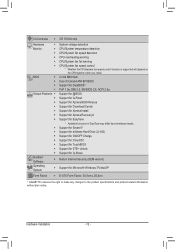
...; Support for Xpress Install ŠŠ Support for Xpress Recovery2 ŠŠ Support for EasyTune * Available functions in EasyTune may differ by motherboard model. ŠŠ Support for Smart 6™ ŠŠ Support for eXtreme Hard Drive (X.H.D) ŠŠ Support for ON/OFF ...138;Š Support for Microsoft® Windows 7/Vista/XP Form Factor ŠŠ E-ATX Form Factor; 30.5cm x 26.4cm * GIGABYTE reserves the right to make any changes to the product specifications and product-related information without prior notice. I/O Controller ŠŠ iTE IT8728...
...; Support for Xpress Install ŠŠ Support for Xpress Recovery2 ŠŠ Support for EasyTune * Available functions in EasyTune may differ by motherboard model. ŠŠ Support for Smart 6™ ŠŠ Support for eXtreme Hard Drive (X.H.D) ŠŠ Support for ON/OFF ...138;Š Support for Microsoft® Windows 7/Vista/XP Form Factor ŠŠ E-ATX Form Factor; 30.5cm x 26.4cm * GIGABYTE reserves the right to make any changes to the product specifications and product-related information without prior notice. I/O Controller ŠŠ iTE IT8728...
User Manual
Page 13
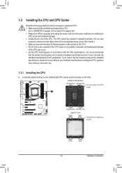
Locate the alignment keys on the motherboard CPU socket and the notches on the surface of the CPU. •• Do not turn off the computer and unplug the power cord from ... to your hardware specifications including the CPU, graphics card, memory, hard drive, etc. 1-3-1 Installing the CPU A. It is not recommended that the motherboard supports the CPU. (Go to GIGABYTE's website for the peripherals. LGA2011 CPU Socket Alignment Key Alignment Key Pin One Corner of the CPU. 1-3 Installing the CPU and CPU Cooler...
Locate the alignment keys on the motherboard CPU socket and the notches on the surface of the CPU. •• Do not turn off the computer and unplug the power cord from ... to your hardware specifications including the CPU, graphics card, memory, hard drive, etc. 1-3-1 Installing the CPU A. It is not recommended that the motherboard supports the CPU. (Go to GIGABYTE's website for the peripherals. LGA2011 CPU Socket Alignment Key Alignment Key Pin One Corner of the CPU. 1-3 Installing the CPU and CPU Cooler...

User Manual
Page 14
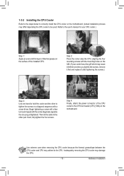
... the power cord from the socket. Step 3: Gently press lever A to allow the load plate to release it when the CPU is inserted into the motherboard CPU socket. •• Before installing the CPU, make sure to turn off from the socket to rise. Remove the cover. Hardware Installation - 14 - Open...
... the power cord from the socket. Step 3: Gently press lever A to allow the load plate to release it when the CPU is inserted into the motherboard CPU socket. •• Before installing the CPU, make sure to turn off from the socket to rise. Remove the cover. Hardware Installation - 14 - Open...
User Manual
Page 15
1-3-2 Installing the CPU Cooler Refer to the steps below to correctly install the CPU cooler on the motherboard. Inadequately removing the CPU cooler may differ depending the CPU cooler to the CPU. Next, fully tighten the four screws. Use extreme care when removing ... pair. Begin tightening a screw with a few turns and repeat with the screw diagonally opposite the one hand to the CPU fan header (CPU_FAN) on the motherboard. (Actual installation process may damage the CPU. - 15 -
1-3-2 Installing the CPU Cooler Refer to the steps below to correctly install the CPU cooler on the motherboard. Inadequately removing the CPU cooler may differ depending the CPU cooler to the CPU. Next, fully tighten the four screws. Use extreme care when removing ... pair. Begin tightening a screw with a few turns and repeat with the screw diagonally opposite the one hand to the CPU fan header (CPU_FAN) on the motherboard. (Actual installation process may damage the CPU. - 15 -
User Manual
Page 16
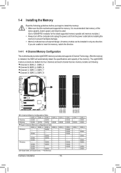
A memory module can be used. (Go to GIGABYTE's website for the latest supported memory speeds and memory modules.) •• Always turn off the computer and unplug the power cord from the power ... as following guidelines before installing the memory to prevent hardware damage. •• Memory modules have a foolproof design. After the memory is recommended that the motherboard supports the memory. DS/SS - - - - - - - - - - DS/SS - - DS/SS - - DS/SS - - (SS=Single-Sided, DS=Double-Sided, "- -"=No Memory) DDR3_5 - DS/SS - DS/SS - - - - - - - - - - DS...
A memory module can be used. (Go to GIGABYTE's website for the latest supported memory speeds and memory modules.) •• Always turn off the computer and unplug the power cord from the power ... as following guidelines before installing the memory to prevent hardware damage. •• Memory modules have a foolproof design. After the memory is recommended that the motherboard supports the memory. DS/SS - - - - - - - - - - DS/SS - - DS/SS - - DS/SS - - (SS=Single-Sided, DS=Double-Sided, "- -"=No Memory) DDR3_5 - DS/SS - DS/SS - - - - - - - - - - DS...

User Manual
Page 17
... sure to begin with two memory modules, we recommend that you install them in the DDR3_1 and DDR3_2 sockets. 2. Place the memory module on this motherboard. Hardware Installation DDR3 and DDR2 DIMMs are not compatible to each channel, such as DDR3_1, DDR3_2, DDR3_3, and DDR3_4. 1-4-2 Installing a Memory Before installing a memory module...
... sure to begin with two memory modules, we recommend that you install them in the DDR3_1 and DDR3_2 sockets. 2. Place the memory module on this motherboard. Hardware Installation DDR3 and DDR2 DIMMs are not compatible to each channel, such as DDR3_1, DDR3_2, DDR3_3, and DDR3_4. 1-4-2 Installing a Memory Before installing a memory module...

User Manual
Page 18
... turn off the computer and unplug the power cord from the power outlet before you begin to install an expansion card: • Make sure the motherboard supports the expansion card. Align the card with your card. Example: Installing and Removing a PCI Express Graphics Card: •• Installing a Graphics Card: Gently push...
... turn off the computer and unplug the power cord from the power outlet before you begin to install an expansion card: • Make sure the motherboard supports the expansion card. Align the card with your card. Example: Installing and Removing a PCI Express Graphics Card: •• Installing a Graphics Card: Gently push...

User Manual
Page 19
... technologies currently support Windows 7, Vista, XP operating systems -- The 3-Way CrossFireX and 3-Way SLI technologies currently support Windows 7 and Vista operating systems -- A CrossFireX/SLI-supported motherboard with sufficient power is enabled. (Note) The bridge connector(s) may differ by graphics cards and driver version. To Enable CrossFireX Function After installing the graphics...
... technologies currently support Windows 7, Vista, XP operating systems -- The 3-Way CrossFireX and 3-Way SLI technologies currently support Windows 7 and Vista operating systems -- A CrossFireX/SLI-supported motherboard with sufficient power is enabled. (Note) The bridge connector(s) may differ by graphics cards and driver version. To Enable CrossFireX Function After installing the graphics...
User Manual
Page 20
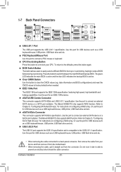
... backup BIOS is compatible to clear the CMOS values (e.g. Clear CMOS Button Use this port to overclock your device and then remove it from the motherboard. •• When removing the cable, pull it side to side to switch between the main BIOS and backup BIOS. Use this button to connect...
... backup BIOS is compatible to clear the CMOS values (e.g. Clear CMOS Button Use this port to overclock your device and then remove it from the motherboard. •• When removing the cable, pull it side to side to switch between the main BIOS and backup BIOS. Use this button to connect...

User Manual
Page 22
... 11) F_AUDIO 12) SPDIF_O 13) F_USB1/F_USB2/F_USB3 14) F_USB30 15) F_1394 16) TPM 17) PW_SW/RST_SW Read the following guidelines before turning on the motherboard. Hardware Installation - 22 - Unplug the power cord from the power outlet to prevent damage to the devices. •• After installing the device and before...
... 11) F_AUDIO 12) SPDIF_O 13) F_USB1/F_USB2/F_USB3 14) F_USB30 15) F_1394 16) TPM 17) PW_SW/RST_SW Read the following guidelines before turning on the motherboard. Hardware Installation - 22 - Unplug the power cord from the power outlet to prevent damage to the devices. •• After installing the device and before...
User Manual
Page 23
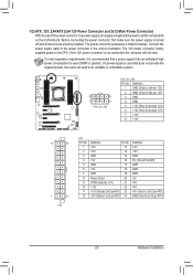
... possesses a foolproof design. Connect the power supply cable to the CPU. If the 12V power connector is turned off and all the components on the motherboard. Hardware Installation 1/2) ATX_12V_2X4/ATX (2x4 12V Power Connector and 2x12 Main Power Connector) With the use of the power connector, the power supply can supply...
... possesses a foolproof design. Connect the power supply cable to the CPU. If the 12V power connector is turned off and all the components on the motherboard. Hardware Installation 1/2) ATX_12V_2X4/ATX (2x4 12V Power Connector and 2x12 Main Power Connector) With the use of the power connector, the power supply can supply...

User Manual
Page 24
3/4) CPU_FAN/SYS_FAN1/2/3/4 (Fan Headers) The motherboard has a 4-pin CPU fan header (CPU_FAN), a 4-pin (SYS_FAN1/2) and the 3-pin (SYS_ FAN3/4) system fan headers. For optimum heat dissipation, it is recommended that a system ...
3/4) CPU_FAN/SYS_FAN1/2/3/4 (Fan Headers) The motherboard has a 4-pin CPU fan header (CPU_FAN), a 4-pin (SYS_FAN1/2) and the 3-pin (SYS_ FAN3/4) system fan headers. For optimum heat dissipation, it is recommended that a system ...

User Manual
Page 28
... output from the HDMI display at the same time. If your expansion card. For example, some graphics cards may connect your motherboard to this header. For information about connecting the S/PDIF digital audio cable, carefully read the manual for digital audio output from your... front panel audio module, refer to1 the instructions on how to work or even damage it. Incorrect connection between the module connector and the motherboard header will make the device unable to activate AC'97 functionality via the audio software in Chapter 5, "Configuring 2/4/5.1/7M.1_-SCAhTAannel Audio." &#...
... output from the HDMI display at the same time. If your expansion card. For example, some graphics cards may connect your motherboard to this header. For information about connecting the S/PDIF digital audio cable, carefully read the manual for digital audio output from your... front panel audio module, refer to1 the instructions on how to work or even damage it. Incorrect connection between the module connector and the motherboard header will make the device unable to activate AC'97 functionality via the audio software in Chapter 5, "Configuring 2/4/5.1/7M.1_-SCAhTAannel Audio." &#...


