
Manual
Page 33
... Drive Activity LED Reset Switch Power LED Chassis Intrusion Header • MSG/PWR (Message/Power/Sleep LED, Yellow/Purple): System Status LED Connects to the power switch on the chassis front panel. The LED is off when the system is detected, the BIOS may differ by ...tem is reading or writing data. • RES (Reset Switch, Green): Connects to the pin assignments below. The system reports system startup status by chassis. When connecting your system using the power switch (refer to Chapter 2, "BIOS Setup," "Power Management Setup," for information about beep codes...
... Drive Activity LED Reset Switch Power LED Chassis Intrusion Header • MSG/PWR (Message/Power/Sleep LED, Yellow/Purple): System Status LED Connects to the power switch on the chassis front panel. The LED is off when the system is detected, the BIOS may differ by ...tem is reading or writing data. • RES (Reset Switch, Green): Connects to the pin assignments below. The system reports system startup status by chassis. When connecting your system using the power switch (refer to Chapter 2, "BIOS Setup," "Power Management Setup," for information about beep codes...

Manual
Page 37
... Inadequately altering the settings may result in system malfunction. • BIOS will emit a beep code during the POST when the power is potentially risky, if you not flash the BIOS. To upgrade the BIOS, use either the GIGABYTE Q-Flash or @BIOS utility. • Q-Flash allows the user to clear the CMOS ...values.) - 37 - If this occurs, try to clear the CMOS values and reset the board to default values. (Refer to the...
... Inadequately altering the settings may result in system malfunction. • BIOS will emit a beep code during the POST when the power is potentially risky, if you not flash the BIOS. To upgrade the BIOS, use either the GIGABYTE Q-Flash or @BIOS utility. • Q-Flash allows the user to clear the CMOS ...values.) - 37 - If this occurs, try to clear the CMOS values and reset the board to default values. (Refer to the...

Manual
Page 41
Auto x Command Rate(CMD) - Auto x tRAS - Auto x tRP - Auto x Command Rate(CMD) - If this occurs, clear the CMOS values and reset the board to default values.) (Note 1) This item appears only if you install a CPU that supports this feature. (Note 2) This item appears only if you ...(M.I.T.) x tRP 7 Auto x tRAS 20 Auto x Command Rate(CMD) 1 Auto >>>>> Channel B x CAS Latency Time - Auto x tRCD - Incorrectly doing overclock/overvoltage may result in damage to boot. BIOS Setup
Auto x Command Rate(CMD) - Auto x tRAS - Auto x tRP - Auto x Command Rate(CMD) - If this occurs, clear the CMOS values and reset the board to default values.) (Note 1) This item appears only if you install a CPU that supports this feature. (Note 2) This item appears only if you ...(M.I.T.) x tRP 7 Auto x tRAS 20 Auto x Command Rate(CMD) 1 Auto >>>>> Channel B x CAS Latency Time - Auto x tRCD - Incorrectly doing overclock/overvoltage may result in damage to boot. BIOS Setup

Manual
Page 45
...(BCLK) Control Enables or disables the control of the PCI Express and North Bridge clock. The adjustable range is from 90 MHz to 1200 MHz. BIOS Setup The adjustable range is from 100 MHz to 150 MHz. Options are : 700mV, 800mV, 900mV (default), 1000mV. PCI Express Clock Drive Allows you... to be configurable. Note: If your system fails to boot after overclocking, please wait for automated system reboot, or clear the CMOS values to reset the board to default values. (Default: Disabled) BCLK Frequency(Mhz) Allows you to set in accordance with the CPU specifications.
...(BCLK) Control Enables or disables the control of the PCI Express and North Bridge clock. The adjustable range is from 90 MHz to 1200 MHz. BIOS Setup The adjustable range is from 100 MHz to 150 MHz. Options are : 700mV, 800mV, 900mV (default), 1000mV. PCI Express Clock Drive Allows you... to be configurable. Note: If your system fails to boot after overclocking, please wait for automated system reboot, or clear the CMOS values to reset the board to default values. (Default: Disabled) BCLK Frequency(Mhz) Allows you to set in accordance with the CPU specifications.

Manual
Page 61
...with EasyTune based on system requirements. 2-8 PC Health Status CMOS Setup Utility-Copyright (C) 1984-2009 Award Software PC Health Status Reset Case Open Status Case Opened Vcore DDR15V +3.3V +5V +12V Current CPU Temperature Current MCH Temperature Current CPU FAN Speed Current...and then restart your system. To clear the chassis intrusion status record, set Reset Case Open Status to Enabled, save the settings to the CPU temperature. When CPU temperature exceeds the threshold, BIOS will show "No" at next boot. (Default: Disabled) Case Opened Displays...
...with EasyTune based on system requirements. 2-8 PC Health Status CMOS Setup Utility-Copyright (C) 1984-2009 Award Software PC Health Status Reset Case Open Status Case Opened Vcore DDR15V +3.3V +5V +12V Current CPU Temperature Current MCH Temperature Current CPU FAN Speed Current...and then restart your system. To clear the chassis intrusion status record, set Reset Case Open Status to Enabled, save the settings to the CPU temperature. When CPU temperature exceeds the threshold, BIOS will show "No" at next boot. (Default: Disabled) Case Opened Displays...

Manual
Page 75
...Enable HDD 1-0 Upda te BIOS from Drive Please SparevsesBaInOySketoy Dtoricvoentinue Enter : Run hi:Move ESC:Reset F10:Power Off - 75 - When the message "Are you save the current BIOS file. • Q-...Reset F10:Power Off Total size : 0 Free size : 0 3. Updating the BIOS When updating the BIOS, choose the location where the BIOS file is updat- appears, press to access Q-Flash. 2. Step 1: 1. Select Floppy A and press . CoaodpyCMBIOOSS DcoemfapuletteEdn-aPbaless !! Update BIOS from Drive Save BIOS to update BIOS?" Make sure the BIOS...
...Enable HDD 1-0 Upda te BIOS from Drive Please SparevsesBaInOySketoy Dtoricvoentinue Enter : Run hi:Move ESC:Reset F10:Power Off - 75 - When the message "Are you save the current BIOS file. • Q-...Reset F10:Power Off Total size : 0 Free size : 0 3. Updating the BIOS When updating the BIOS, choose the location where the BIOS file is updat- appears, press to access Q-Flash. 2. Step 1: 1. Select Floppy A and press . CoaodpyCMBIOOSS DcoemfapuletteEdn-aPbaless !! Update BIOS from Drive Save BIOS to update BIOS?" Make sure the BIOS...

Manual
Page 80
... (Note 1) Before using the Dynamic Energy SaverTM 2 function, make sure the CPU Enhanced Halt (C1E) and CPU EIST Function items in the BIOS Setup program are able to run in a set to zero. (Note 4) Dynamic Energy Saver Meter will continue to see how much total power ... 9 3-Level Power Saving Switch (Default:1) (Note 2) 10 Advanced Settings 11 Close (Application will enter Stealth Mode) 12 Minimize (Application will automatically reset when the total power saving reaches 99999999 Watts. B. Total Mode In Total Mode, users are set period of power saved will be recorded until re...
... (Note 1) Before using the Dynamic Energy SaverTM 2 function, make sure the CPU Enhanced Halt (C1E) and CPU EIST Function items in the BIOS Setup program are able to run in a set to zero. (Note 4) Dynamic Energy Saver Meter will continue to see how much total power ... 9 3-Level Power Saving Switch (Default:1) (Note 2) 10 Advanced Settings 11 Close (Application will enter Stealth Mode) 12 Minimize (Application will automatically reset when the total power saving reaches 99999999 Watts. B. Total Mode In Total Mode, users are set period of power saved will be recorded until re...

Manual
Page 91
Figure 2 Step 2: After you want to create a RAID array, select Create RAID Volume in RAID BIOS Enter the RAID BIOS setup utility to configure a RAID array. Create RAID Volume 2. Reset Disks to enter Configuration Utility.. C. Configuring a RAID array in MAIN MENU and press . RAID Volumes : None defined. Create RAID Volume If you press + , the...
Figure 2 Step 2: After you want to create a RAID array, select Create RAID Volume in RAID BIOS Enter the RAID BIOS setup utility to configure a RAID array. Create RAID Volume 2. Reset Disks to enter Configuration Utility.. C. Configuring a RAID array in MAIN MENU and press . RAID Volumes : None defined. Create RAID Volume If you press + , the...

Manual
Page 93
... Size 111.7GB 111.7GB Type/Status(Vol ID) Member Disk(0) Member Disk(0) [hi]-Select [ESC]-Exit Figure 7 [ENTER]-Select Menu To exit the RAID BIOS utility, press or select 5. Step 5: Enter the array capacity and press . Finally press on the Create Volume item to Non-RAID 4. All Rights Reserved. [ MAIN... RAID/AHCI driver diskette and install the SATA RAID/AHCI driver and operating system. - 93 - Now, you can proceed to cancel (Figure 6). Delete RAID Volume 5. Reset Disks to begin creating the RAID array.
... Size 111.7GB 111.7GB Type/Status(Vol ID) Member Disk(0) Member Disk(0) [hi]-Select [ESC]-Exit Figure 7 [ENTER]-Select Menu To exit the RAID BIOS utility, press or select 5. Step 5: Enter the array capacity and press . Finally press on the Create Volume item to Non-RAID 4. All Rights Reserved. [ MAIN... RAID/AHCI driver diskette and install the SATA RAID/AHCI driver and operating system. - 93 - Now, you can proceed to cancel (Figure 6). Delete RAID Volume 5. Reset Disks to begin creating the RAID array.
Manual
Page 134
...-detection of DRAM size, type and ECC Expand compressed BIOS code to DRAM Call chipset hook to copy BIOS back to check out interface in physical address 1000:0 DualBIOS init (optional) Initial Superio_Early_Init switch 1. Enable keyboard interface 1. Reset keyboard Super I /O chips 2. Also set real-time...basic chipset registers Detect memory - If test fails, keep beeping the speaker Auto detect flash type to load appropriate flash R/W codes into BIOS stack. If CMOS checksum fails, use default value instead Appendix - 134 - 5-4 POST Error Code POST (hex) CFh C0h C1h C3h...
...-detection of DRAM size, type and ECC Expand compressed BIOS code to DRAM Call chipset hook to copy BIOS back to check out interface in physical address 1000:0 DualBIOS init (optional) Initial Superio_Early_Init switch 1. Enable keyboard interface 1. Reset keyboard Super I /O chips 2. Also set real-time...basic chipset registers Detect memory - If test fails, keep beeping the speaker Auto detect flash type to load appropriate flash R/W codes into BIOS stack. If CMOS checksum fails, use default value instead Appendix - 134 - 5-4 POST Error Code POST (hex) CFh C0h C1h C3h...

Manual
Page 135
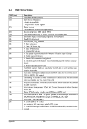
... 2Bh 2Dh 33h 35h 37h 39h 3Ch 3Eh 40h 43h 47h 49h 4Eh 50h 52h 53h 55h 57h Description Prepare BIOS resource map for channel 2 Test 8259 functionality Initialize EISA slot 1. Winbond 977 series Super I /O resource - ..., including Award title, CPU type, CPU speed, full screen logo Reset keyboard if Early_Reset_KB is not defined Onboard clock generator initialization. Appendix Search for a valid VGA device & VGA BIOS, and put it into consideration of processors (multi-processor platform) ...
... 2Bh 2Dh 33h 35h 37h 39h 3Ch 3Eh 40h 43h 47h 49h 4Eh 50h 52h 53h 55h 57h Description Prepare BIOS resource map for channel 2 Test 8259 functionality Initialize EISA slot 1. Winbond 977 series Super I /O resource - ..., including Award title, CPU type, CPU speed, full screen logo Reset keyboard if Early_Reset_KB is not defined Onboard clock generator initialization. Appendix Search for a valid VGA device & VGA BIOS, and put it into consideration of processors (multi-processor platform) ...


