Manual
Page 4
Table of Contents Box Contents...6 Optional Items...6 GA-X58A-UD3R Motherboard Layout 7 GA-X58A-UD3R Block Diagram 8 Chapter 1 Hardware Installation 9 1-1 Installation Precautions 9 1-2 Product Specifications 10 1-3 Installing the CPU and CPU Cooler 13 1-3-1 Installing the CPU 13 1-3-2 Installing the CPU Cooler 15 1-4 Installing the Memory 16 1-4-1 Dual/3 Channel Memory Configuration 16 1-4-2 Installing a Memory 17 1-5 Installing an Expansion Card 18 1-6 Setup of...
Table of Contents Box Contents...6 Optional Items...6 GA-X58A-UD3R Motherboard Layout 7 GA-X58A-UD3R Block Diagram 8 Chapter 1 Hardware Installation 9 1-1 Installation Precautions 9 1-2 Product Specifications 10 1-3 Installing the CPU and CPU Cooler 13 1-3-1 Installing the CPU 13 1-3-2 Installing the CPU Cooler 15 1-4 Installing the Memory 16 1-4-1 Dual/3 Channel Memory Configuration 16 1-4-2 Installing a Memory 17 1-5 Installing an Expansion Card 18 1-6 Setup of...
Manual
Page 8
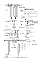
GA-X58A-UD3R Block Diagram 2 PCI Express x16 4 PCI Express x8 PCIe CLK (100 MHz) or LGA1366 CPU CPU CLK+/- (133 MHz) DDR3 2200/1333/1066/800 MHz Dual/3 Channel Memory QPI x16 x8 PCI Express Bus PCIe CLK (100 MHz) Switch LAN RJ45 RTL8111D Interface Intel® X58 IOH CLK (133 MHz)... Express x1 x1 2 eSATA 3Gb/s 2 SATA 6Gb/s 2 USB 3.0 Dual BIOS 6 SATA 3Gb/s 12 USB 2.0/1.1 (Note) 2 SATA 3Gb/s ATA-133/100/66/33 IDE Channel GIGABYTE SATA2 PCI Bus TSB43AB23 CODEC LPC Bus IT8720 Floppy PS/2 KB/Mouse 3 IEEE 1394a Surround Speaker Out Center/Subwoofer Speaker Out Side Speaker Out MIC...
GA-X58A-UD3R Block Diagram 2 PCI Express x16 4 PCI Express x8 PCIe CLK (100 MHz) or LGA1366 CPU CPU CLK+/- (133 MHz) DDR3 2200/1333/1066/800 MHz Dual/3 Channel Memory QPI x16 x8 PCI Express Bus PCIe CLK (100 MHz) Switch LAN RJ45 RTL8111D Interface Intel® X58 IOH CLK (133 MHz)... Express x1 x1 2 eSATA 3Gb/s 2 SATA 6Gb/s 2 USB 3.0 Dual BIOS 6 SATA 3Gb/s 12 USB 2.0/1.1 (Note) 2 SATA 3Gb/s ATA-133/100/66/33 IDE Channel GIGABYTE SATA2 PCI Bus TSB43AB23 CODEC LPC Bus IT8720 Floppy PS/2 KB/Mouse 3 IEEE 1394a Surround Speaker Out Center/Subwoofer Speaker Out Side Speaker Out MIC...
Manual
Page 9
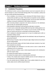
... components. • When connecting hardware components to the internal connectors on the computer power during the installation process can become damaged as a motherboard, CPU or memory. Hardware Installation ponents such as a result of your dealer.
... components. • When connecting hardware components to the internal connectors on the computer power during the installation process can become damaged as a motherboard, CPU or memory. Hardware Installation ponents such as a result of your dealer.
Manual
Page 10
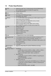
...® Core™ i7 series processor in the LGA1366 package (Go to GIGABYTE's website for the latest CPU support list.) L3 cache varies with CPU QPI 4.8GT/s, 6.4GT/s Chipset Memory Audio North Bridge: Intel® X58 Express Chipset South...24 GB of system memory (Note 1) Dual/3 channel memory architecture Support for DDR3 2200/1333/1066/800 MHz memory modules Support for non-ECC memory modules Support for Extreme Memory Profile (XMP) memory modules (Go to GIGABYTE's website for the latest memory support list.) ...
...® Core™ i7 series processor in the LGA1366 package (Go to GIGABYTE's website for the latest CPU support list.) L3 cache varies with CPU QPI 4.8GT/s, 6.4GT/s Chipset Memory Audio North Bridge: Intel® X58 Express Chipset South...24 GB of system memory (Note 1) Dual/3 channel memory architecture Support for DDR3 2200/1333/1066/800 MHz memory modules Support for non-ECC memory modules Support for Extreme Memory Profile (XMP) memory modules (Go to GIGABYTE's website for the latest memory support list.) ...
Manual
Page 12
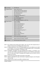
.../Power fan speed detection CPU overheating warning CPU fan fail warning CPU/System fan speed control (Note 5) 2 x 16 Mbit flash Use of physical memory is installed, the actual memory size displayed will depend on the CPU/system cooler you install them in the PCIEX16_1 and PCIEX16_2 slots. (Note 3) The PCIEX8_1 and PCIEX8_2...
.../Power fan speed detection CPU overheating warning CPU fan fail warning CPU/System fan speed control (Note 5) 2 x 16 Mbit flash Use of physical memory is installed, the actual memory size displayed will depend on the CPU/system cooler you install them in the PCIEX16_1 and PCIEX16_2 slots. (Note 3) The PCIEX8_1 and PCIEX8_2...
Manual
Page 13
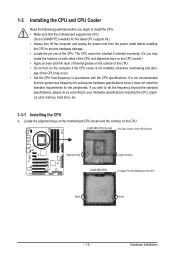
If you wish to set beyond the standard specifications, please do so according to your hardware specifications including the CPU, graphics card, memory, hard drive, etc. 1-3-1 Installing the CPU A. Hardware Installation LGA1366 CPU Socket Pin One Corner of the CPU Socket Alignment Key Alignment ...CPU support list.) • Always turn on the computer if the CPU cooler is not recommended that the motherboard supports the CPU. (Go to GIGABYTE's website for the peripherals. 1-3 Installing the CPU and CPU Cooler Read the following guidelines before you begin to install the CPU: • ...
If you wish to set beyond the standard specifications, please do so according to your hardware specifications including the CPU, graphics card, memory, hard drive, etc. 1-3-1 Installing the CPU A. Hardware Installation LGA1366 CPU Socket Pin One Corner of the CPU Socket Alignment Key Alignment ...CPU support list.) • Always turn on the computer if the CPU cooler is not recommended that the motherboard supports the CPU. (Go to GIGABYTE's website for the peripherals. 1-3 Installing the CPU and CPU Cooler Read the following guidelines before you begin to install the CPU: • ...
Manual
Page 16
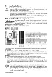
...capacity, brand, speed, and chips be installed in Flex Memory Mode will automatically detect the specifications and capacity of the same capacity, brand, speed, and chips be used . (Go to GIGABYTE's website for the latest memory support list.) • Always turn off the computer ...and unplug the power cord from the power outlet before you are unable to install the memory: • Make sure that memory of the memory. Intel?Flex Memory Technology offers greater flexibility...
...capacity, brand, speed, and chips be installed in Flex Memory Mode will automatically detect the specifications and capacity of the same capacity, brand, speed, and chips be used . (Go to GIGABYTE's website for the latest memory support list.) • Always turn off the computer ...and unplug the power cord from the power outlet before you are unable to install the memory: • Make sure that memory of the memory. Intel?Flex Memory Technology offers greater flexibility...

Manual
Page 17
...and DDR2 DIMMs are not compatible to each other or DDR DIMMs. Be sure to the memory module. Hardware Installation Step 1: Note the orientation of the memory, push down on the memory and insert it can only fit in one direction. Spread the retaining clips at both ends ... your fingers on the top edge of the memory module. Notch DDR3 DIMM A DDR3 memory module has a notch, so it vertically into place when the memory module is securely inserted. - 17 - Place the memory module on the socket. 1-4-2 Installing a Memory Before installing a memory module, make sure to turn off the computer...
...and DDR2 DIMMs are not compatible to each other or DDR DIMMs. Be sure to the memory module. Hardware Installation Step 1: Note the orientation of the memory, push down on the memory and insert it can only fit in one direction. Spread the retaining clips at both ends ... your fingers on the top edge of the memory module. Notch DDR3 DIMM A DDR3 memory module has a notch, so it vertically into place when the memory module is securely inserted. - 17 - Place the memory module on the socket. 1-4-2 Installing a Memory Before installing a memory module, make sure to turn off the computer...

Manual
Page 22
...) L2: Level 2 (Moderate, yellow) L3: Level 3 (High, red) Overclock LEDs The onboard CPU overclock LEDs indicate on which indicate the overvoltage level of the CPU, memory, North Bridge, and South Bridge. The LEDs are off when the temperature is below 60oC;
...) L2: Level 2 (Moderate, yellow) L3: Level 3 (High, red) Overclock LEDs The onboard CPU overclock LEDs indicate on which indicate the overvoltage level of the CPU, memory, North Bridge, and South Bridge. The LEDs are off when the temperature is below 60oC;

Manual
Page 23
NB PHASE LED The number of lighted LEDs indicates the memory loading. DDR PHASE LED The number of lighted LEDs indicates the North Bridge loading. To enable the Phase LED display function, please first enable Dynamic ..., the more the number of lighted LEDs. The higher the North Bridge loading, the more the number of lighted LEDs. Hardware Installation The higher the memory loading, the more details. PHASE LED The number of lighted LEDs. - 23 -
NB PHASE LED The number of lighted LEDs indicates the memory loading. DDR PHASE LED The number of lighted LEDs indicates the North Bridge loading. To enable the Phase LED display function, please first enable Dynamic ..., the more the number of lighted LEDs. The higher the North Bridge loading, the more the number of lighted LEDs. Hardware Installation The higher the memory loading, the more details. PHASE LED The number of lighted LEDs. - 23 -
Manual
Page 38
First enter the profile name (to erase the default profile name, use this function to load the BIOS settings from BIOS If your CPU, memory, etc. Standard CMOS Features Use this menu to configure the system time and date, hard drive types, floppy disk drive types, and the type ...
First enter the profile name (to erase the default profile name, use this function to load the BIOS settings from BIOS If your CPU, memory, etc. Standard CMOS Features Use this menu to configure the system time and date, hard drive types, floppy disk drive types, and the type ...

Manual
Page 39
...QPI Link Speed } UnCore & QPI Features Base Clock(BCLK) Control x BCLK Frequency (Mhz) } Advanced Clock Control Performance Enhance Extreme Memory Profile (X.M.P.) (Note 2) System Memory Multiplier (SPD) Memory Frequency (Mhz) 1066 DRAM Timing Selectable (SPD) Profile DDR Voltage Profile QPI Voltage >>>>> Channel A x CAS Latency Time 8 x ...if you install a CPU that supports this feature. (Note 2) This item appears only if you install a memory module that supports this feature. - 39 - If this occurs, clear the CMOS values and reset the board to CPU, chipset,...
...QPI Link Speed } UnCore & QPI Features Base Clock(BCLK) Control x BCLK Frequency (Mhz) } Advanced Clock Control Performance Enhance Extreme Memory Profile (X.M.P.) (Note 2) System Memory Multiplier (SPD) Memory Frequency (Mhz) 1066 DRAM Timing Selectable (SPD) Profile DDR Voltage Profile QPI Voltage >>>>> Channel A x CAS Latency Time 8 x ...if you install a CPU that supports this feature. (Note 2) This item appears only if you install a memory module that supports this feature. - 39 - If this occurs, clear the CMOS values and reset the board to CPU, chipset,...

Manual
Page 44
...allows all DRAM timing control items below to operate at three different performance levels. the second is the memory frequency that supports this function. (Default) Profile1 Uses Profile 1 settings. Standard Lets the system operate at...******** Advanced DRAM Features ******** CMOS Setup Utility-Copyright (C) 1984-2009 Award Software Advanced DRAM Features Performance Enhance Extreme Memory Profile (X.M.P.) (Note) System Memory Multiplier (SPD) Memory Frequency (Mhz) 1066 DRAM Timing Selectable (SPD) Profile DDR Voltage Profile QPI Voltage x Channel Interleaving 6 x...
...allows all DRAM timing control items below to operate at three different performance levels. the second is the memory frequency that supports this function. (Default) Profile1 Uses Profile 1 settings. Standard Lets the system operate at...******** Advanced DRAM Features ******** CMOS Setup Utility-Copyright (C) 1984-2009 Award Software Advanced DRAM Features Performance Enhance Extreme Memory Profile (X.M.P.) (Note) System Memory Multiplier (SPD) Memory Frequency (Mhz) 1066 DRAM Timing Selectable (SPD) Profile DDR Voltage Profile QPI Voltage x Channel Interleaving 6 x...

Manual
Page 49
... CMOS Setup Utility-Copyright (C) 1984-2009 Award Software Standard CMOS Features Drive A Halt On [1.44M, 3.5"] [All, But Keyboard] Item Help Menu Level Base Memory Extended Memory Total Memory 640K 1022M 1024M Move Enter: Select F5: Previous Values +/-/PU/PD: Value F10: Save F6: Fail-Safe Defaults ESC: Exit F1: General Help F7...
... CMOS Setup Utility-Copyright (C) 1984-2009 Award Software Standard CMOS Features Drive A Halt On [1.44M, 3.5"] [All, But Keyboard] Item Help Menu Level Base Memory Extended Memory Total Memory 640K 1022M 1024M Move Enter: Select F5: Previous Values +/-/PU/PD: Value F10: Save F6: Fail-Safe Defaults ESC: Exit F1: General Help F7...

Manual
Page 50
... your IDE/SATA devices by the BIOS POST. Head Number of cylinders. Precomp Write precompensation cylinder. Sector Number of extended memory. Access Mode Sets the hard drive access mode. Landing Zone Landing zone. Options are determined by using one of the two...boot will stop . Options are : Auto (default), Large. If you to the information on the system. Base Memory Also called conventional memory. Total Memory The total amount of floppy disk drive installed in your hard drive specifications. Access Mode Sets the hard drive access ...
... your IDE/SATA devices by the BIOS POST. Head Number of cylinders. Precomp Write precompensation cylinder. Sector Number of extended memory. Access Mode Sets the hard drive access mode. Landing Zone Landing zone. Options are determined by using one of the two...boot will stop . Options are : Auto (default), Large. If you to the information on the system. Base Memory Also called conventional memory. Total Memory The total amount of floppy disk drive installed in your hard drive specifications. Access Mode Sets the hard drive access ...

Manual
Page 51
... time the system boots, or only when you install a CPU that supports this menu when finished. HDD S.M.A.R.T. Capability Limit CPUID Max. to 3 (Note) No-Execute Memory Protect (Note) Delay For HDD (Secs) Full Screen LOGO Show Backup BIOS Image to move it up or down arrow key to select a hard drive...
... time the system boots, or only when you install a CPU that supports this menu when finished. HDD S.M.A.R.T. Capability Limit CPUID Max. to 3 (Note) No-Execute Memory Protect (Note) Delay For HDD (Secs) Full Screen LOGO Show Backup BIOS Image to move it up or down arrow key to select a hard drive...

Manual
Page 52
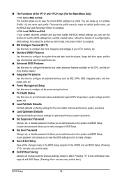
... viruses and malicious buffer overflow attacks when working with its sup- BIOS Setup - 52 - set a delay time for the computer, reducing exposure to display the GIGABYTE Logo at system startup. For more information about Intel CPUs' unique features, please visit Intel's website. This function may enhance protection for the BIOS to... BIOS Image to HDD Allows the system to copy the BIOS image file to initialize the hard drive as Windows NT4.0. (Default: Disabled) No-Execute Memory Protect (Note) Enables or disables Intel Execute Disable Bit function.
... viruses and malicious buffer overflow attacks when working with its sup- BIOS Setup - 52 - set a delay time for the computer, reducing exposure to display the GIGABYTE Logo at system startup. For more information about Intel CPUs' unique features, please visit Intel's website. This function may enhance protection for the BIOS to... BIOS Image to HDD Allows the system to copy the BIOS image file to initialize the hard drive as Windows NT4.0. (Default: Disabled) No-Execute Memory Protect (Note) Enables or disables Intel Execute Disable Bit function.
Manual
Page 58
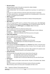
... is set to Password. To turn on the system. When prompted for the password, press again without entering the password to turn on the system. Memory The system returns to its last known awake state upon the return of power from the operating system or removal of the AC power. HPET...
... is set to Password. To turn on the system. When prompted for the password, press again without entering the password to turn on the system. Memory The system returns to its last known awake state upon the return of power from the operating system or removal of the AC power. HPET...
Manual
Page 69
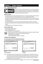
... operating system and drivers are installed. • The amount of data and hard drive access speed may affect the speed at the end of system memory • VESA compatible graphics card • Windows XP with Xpress Recovery cannot be restored using Xpress Recovery2. • USB hard drives are not supported. •...
... operating system and drivers are installed. • The amount of data and hard drive access speed may affect the speed at the end of system memory • VESA compatible graphics card • Windows XP with Xpress Recovery cannot be restored using Xpress Recovery2. • USB hard drives are not supported. •...

Manual
Page 76
... Monitor tab allows you must install a DDR3 1066 MHz memory module(s) (or above) to change the core clock and memory clock for your ATI or NVIDIA graphics card. You can select memory module on the CPU temperature thresholds you to enable support ...easy-to-use your system for Quick Boost. 4-3 EasyTune 6 GIGABYTE's EasyTune 6 is not supported. The EasyTune 6 Interface Tabs Information Tab Function The CPU tab provides information on the installed memory module(s). The Memory tab provides information on the installed CPU and motherboard. Incorrectly ...
... Monitor tab allows you must install a DDR3 1066 MHz memory module(s) (or above) to change the core clock and memory clock for your ATI or NVIDIA graphics card. You can select memory module on the CPU temperature thresholds you to enable support ...easy-to-use your system for Quick Boost. 4-3 EasyTune 6 GIGABYTE's EasyTune 6 is not supported. The EasyTune 6 Interface Tabs Information Tab Function The CPU tab provides information on the installed memory module(s). The Memory tab provides information on the installed CPU and motherboard. Incorrectly ...


