Manual
Page 1
GA-X58A-OC User's Manual Rev. 1001 12ME-X58AOC-1001R
GA-X58A-OC User's Manual Rev. 1001 12ME-X58AOC-1001R
Manual
Page 2
Motherboard GA-X58A-OC Mar. 22, 2011 Motherboard GA-X58A-OC Mar. 22, 2011
Motherboard GA-X58A-OC Mar. 22, 2011 Motherboard GA-X58A-OC Mar. 22, 2011
Manual
Page 4
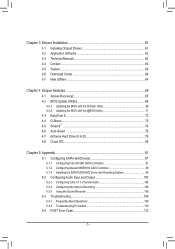
Table of Contents Box Contents...6 Optional Items...6 GA-X58A-OC Motherboard Layout 7 GA-X58A-OC Motherboard Block Diagram 8 Chapter 1 Hardware Installation 9 1-1 Installation Precautions 9 1-2 Product Specifications 10 1-3 Installing the CPU and CPU Cooler 13 1-3-1 Installing the CPU 13 1-3-2 Installing the CPU ...
Table of Contents Box Contents...6 Optional Items...6 GA-X58A-OC Motherboard Layout 7 GA-X58A-OC Motherboard Block Diagram 8 Chapter 1 Hardware Installation 9 1-1 Installation Precautions 9 1-2 Product Specifications 10 1-3 Installing the CPU and CPU Cooler 13 1-3-1 Installing the CPU 13 1-3-2 Installing the CPU ...
Manual
Page 5
... Utility 68 4-2-2 Updating the BIOS with the @BIOS Utility 71 4-3 EasyTune 6...72 4-4 Q-Share...73 4-5 Smart 6™ ...74 4-6 Auto Green...78 4-7 eXtreme Hard Drive (X.H.D 79 4-8 Cloud OC...80 Chapter 5 Appendix...81 5-1 Configuring SATA Hard Drive(s 81 5-1-1 Configuring Intel ICH10R SATA Controllers 81 5-1-2 Configuring Marvell 88SE9182 SATA Controller 89 5-1-3 Installing the SATA RAID...
... Utility 68 4-2-2 Updating the BIOS with the @BIOS Utility 71 4-3 EasyTune 6...72 4-4 Q-Share...73 4-5 Smart 6™ ...74 4-6 Auto Green...78 4-7 eXtreme Hard Drive (X.H.D 79 4-8 Cloud OC...80 Chapter 5 Appendix...81 5-1 Configuring SATA Hard Drive(s 81 5-1-1 Configuring Intel ICH10R SATA Controllers 81 5-1-2 Configuring Marvell 88SE9182 SATA Controller 89 5-1-3 Installing the SATA RAID...
Manual
Page 6
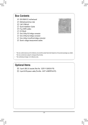
Optional Items 2-port USB 2.0 bracket (Part No. 12CR1-1UB030-5*R) 2-port SATA power cable (Part No. 12CF1-2SERPW-0*R) - 6 - Box Contents GA-X58A-OC motherboard Motherboard driver disk User's Manual Quick Installation Guide Four SATA cables I/O Shield One 2-Way SLI bridge connector One 3-Way SLI bridge connector One 2-Way ...
Optional Items 2-port USB 2.0 bracket (Part No. 12CR1-1UB030-5*R) 2-port SATA power cable (Part No. 12CF1-2SERPW-0*R) - 6 - Box Contents GA-X58A-OC motherboard Motherboard driver disk User's Manual Quick Installation Guide Four SATA cables I/O Shield One 2-Way SLI bridge connector One 3-Way SLI bridge connector One 2-Way ...
Manual
Page 7
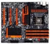
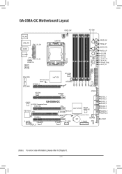
GA-X58A-OC Motherboard Layout CMOS_SW 4G Gear DIP 1 23 + _+ _ KB_MS USB_LAN AUDIO ATX_12V_2X1 R_USB3 ATX_12V_2X Realtek RTL8111E Etron EJ168 SW1 LGA1366 FREQ_DW FREQ_UP RATIO_DW SYS_FAN1 ...DDR3_1 DDR3_4 DDR3_3 DDR3_6 DDR3_5 Debug LED (Note) SYS_FAN6 SYS_FAN5 MCH Temperature Sensor PCIEX16_1 Intel® X58 CPU_FAN HP_PWR1 NB_FAN PCIEX8_1 SYS_FAN2 ATX4P4 CODEC GA-X58A-OC SYSTEM1 Temperature Sensor PCIEX16_2 iTE IT8720 PCI PCIEX8_2 F_AUDIO SYS_FAN4 SPDIF_O M_BIOS B_BIOS SYS_FAN3 Intel® ICH10R Marvell 88SE9182 MBIOS_LED BBIOS_LED F_USB1 SYSTEM2 Temperature ...
GA-X58A-OC Motherboard Layout CMOS_SW 4G Gear DIP 1 23 + _+ _ KB_MS USB_LAN AUDIO ATX_12V_2X1 R_USB3 ATX_12V_2X Realtek RTL8111E Etron EJ168 SW1 LGA1366 FREQ_DW FREQ_UP RATIO_DW SYS_FAN1 ...DDR3_1 DDR3_4 DDR3_3 DDR3_6 DDR3_5 Debug LED (Note) SYS_FAN6 SYS_FAN5 MCH Temperature Sensor PCIEX16_1 Intel® X58 CPU_FAN HP_PWR1 NB_FAN PCIEX8_1 SYS_FAN2 ATX4P4 CODEC GA-X58A-OC SYSTEM1 Temperature Sensor PCIEX16_2 iTE IT8720 PCI PCIEX8_2 F_AUDIO SYS_FAN4 SPDIF_O M_BIOS B_BIOS SYS_FAN3 Intel® ICH10R Marvell 88SE9182 MBIOS_LED BBIOS_LED F_USB1 SYSTEM2 Temperature ...
Manual
Page 8
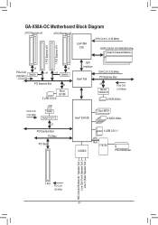
GA-X58A-OC Motherboard Block Diagram 2 PCI Express x8 2 PCI Express x8 LGA1366 CPU CPU CLK+/- (133 MHz) DDR3 2200/1333/1066/800 MHz Dual/3 Channel Memory 1 PCI ...
GA-X58A-OC Motherboard Block Diagram 2 PCI Express x8 2 PCI Express x8 LGA1366 CPU CPU CLK+/- (133 MHz) DDR3 2200/1333/1066/800 MHz Dual/3 Channel Memory 1 PCI ...
Manual
Page 11
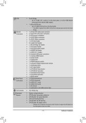
...;Š 1 x power button ŠŠ 1 x reset button ŠŠ 1 x PWM frequency switch ŠŠ 1 x onboard voltage measurement module ŠŠ 1 x 4G Ready button ŠŠ 1 x OC Gear button ŠŠ 1 x CPU BCLK Down button ŠŠ 1 x CPU BCLK Up button ŠŠ 1 x CPU Ratio Down button ŠŠ 1 x CPU Ratio Up...
...;Š 1 x power button ŠŠ 1 x reset button ŠŠ 1 x PWM frequency switch ŠŠ 1 x onboard voltage measurement module ŠŠ 1 x 4G Ready button ŠŠ 1 x OC Gear button ŠŠ 1 x CPU BCLK Down button ŠŠ 1 x CPU BCLK Up button ŠŠ 1 x CPU Ratio Down button ŠŠ 1 x CPU Ratio Up...
Manual
Page 12
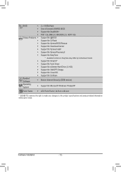
...Support for Auto Green ŠŠ Support for eXtreme Hard Drive (X.H.D) ŠŠ Support for ON/OFF Charge ŠŠ Support for Cloud OC ŠŠ Support for Q-Share Bundled Software ŠŠ Norton Internet Security (OEM version) Operating System ŠŠ Support for Microsoft®... Windows 7/Vista/XP Form Factor ŠŠ ATX Form Factor; 30.5cm x 26.4cm * GIGABYTE reserves the right to make any changes to the product specifications and product-related information without prior notice. Hardware Installation - 12 -
...Support for Auto Green ŠŠ Support for eXtreme Hard Drive (X.H.D) ŠŠ Support for ON/OFF Charge ŠŠ Support for Cloud OC ŠŠ Support for Q-Share Bundled Software ŠŠ Norton Internet Security (OEM version) Operating System ŠŠ Support for Microsoft®... Windows 7/Vista/XP Form Factor ŠŠ ATX Form Factor; 30.5cm x 26.4cm * GIGABYTE reserves the right to make any changes to the product specifications and product-related information without prior notice. Hardware Installation - 12 -
Manual
Page 22
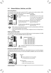
...Down Button (FREQ_DW) CPU BCLK Up Button (FREQ_UP) Lowers the CPU base clock. PWM Frequency Switch (SW1) PWM Switch (X58A-OC) DIP 1 23 BIOS Switcher (X58A-OC) The PWM frequency switch allows users to reduce BIOS failure during overclocking. DIP 1 23 BIOS Switch: DIP SW4 ON: ...(Boot from the main BIOS) F_PANEL (H61M-D2) DIP 1 23 1 DIP 1 23 1 F_PANEL(NH) PWM Switch (X58A-OC) BIOS Switcher (X58A-OC) DIP 1 23 1 DIP 1 23 PCIe power connector (SATA)(X58A-OC) 1 BIOS LED Indicators: MBIOS_LED (The main BIOS is active) BBIOS_LED (The backup BIOS is active. 1-8 Onboard Buttons, Switches...
...Down Button (FREQ_DW) CPU BCLK Up Button (FREQ_UP) Lowers the CPU base clock. PWM Frequency Switch (SW1) PWM Switch (X58A-OC) DIP 1 23 BIOS Switcher (X58A-OC) The PWM frequency switch allows users to reduce BIOS failure during overclocking. DIP 1 23 BIOS Switch: DIP SW4 ON: ...(Boot from the main BIOS) F_PANEL (H61M-D2) DIP 1 23 1 DIP 1 23 1 F_PANEL(NH) PWM Switch (X58A-OC) BIOS Switcher (X58A-OC) DIP 1 23 1 DIP 1 23 PCIe power connector (SATA)(X58A-OC) 1 BIOS LED Indicators: MBIOS_LED (The main BIOS is active) BBIOS_LED (The backup BIOS is active. 1-8 Onboard Buttons, Switches...
Manual
Page 23
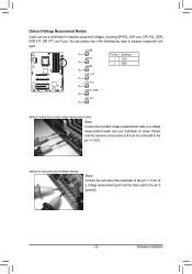
...gXe5n8mtAme-aOosVdCuou)rleteam(gXee5n8mtAme-aOosVdCuuor)letam(gXe5n8mtAme-aOosVdCuou)rleteam(gXe5nm8tAme-aOosVdCuour)lleteam(gXe5nm8tAme-aOosdCuur)leem(Xe5n8tAm-OodCu)le(X58A-OC) TPM TPM TPM TPM TPM TPM TPM w/housing w/housing w/housing w/housing w/housing w/housing w/...e(Sr AcPoTCnAIne)(eXpc5oto8wrAe(-rSOcAPCoTCn)AIne)e(Xpc5too8wrAe(-SrOAcPCoTCnA)In)e(eXpc5oto8wrAe(-SrOcAPCoTCn)AIne)(eXpco5tow8rAe(-rSOcAPCoTCn)AIne)e(Xpcot5ow8rAe(Sr-OcAoCTnA)n)e(Xc5to8rA(-SOACT)A)(X58A-OC) Pin No. Onboard Voltage Measurement1 Module DIP Users can employ one ofDIP the following two ways to measure...
...gXe5n8mtAme-aOosVdCuou)rleteam(gXee5n8mtAme-aOosVdCuuor)letam(gXe5n8mtAme-aOosVdCuou)rleteam(gXe5nm8tAme-aOosVdCuour)lleteam(gXe5nm8tAme-aOosdCuur)leem(Xe5n8tAm-OodCu)le(X58A-OC) TPM TPM TPM TPM TPM TPM TPM w/housing w/housing w/housing w/housing w/housing w/housing w/...e(Sr AcPoTCnAIne)(eXpc5oto8wrAe(-rSOcAPCoTCn)AIne)e(Xpc5too8wrAe(-SrOAcPCoTCnA)In)e(eXpc5oto8wrAe(-SrOcAPCoTCn)AIne)(eXpco5tow8rAe(-rSOcAPCoTCn)AIne)e(Xpcot5ow8rAe(Sr-OcAoCTnA)n)e(Xc5to8rA(-SOACT)A)(X58A-OC) Pin No. Onboard Voltage Measurement1 Module DIP Users can employ one ofDIP the following two ways to measure...
Manual
Page 28
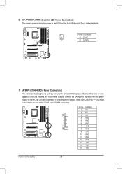
Definition 1 VCC 1 2 GND 1 F_PANEL (H61M-D2) F_PANEL(NH) 7) ATX4P1/ATX4P4 (PCIe Power Connectors) PWM Switch (X58A-OC) BIOS Switcher (X58A-OC) The power connectors provide auxiliary power to the LEDs on the North Bridge and South Bridge heatsinks. DIP 1 23 Pin No. When ...must connect at least one of the ATX4P1 and AT1 X2 34P4 connectors. 1 DIP 1 23 PCIe power connector (SATA)(X58A-OC) DIP 1 23 1 DIP 1 23 1 DIP 1 2 31 Voltage measurement module(X58A-OC) DB_PORT Pin No. For 4-way CrossFireX™, you connect the SATA power cable(s) from the power supply to the ...
Definition 1 VCC 1 2 GND 1 F_PANEL (H61M-D2) F_PANEL(NH) 7) ATX4P1/ATX4P4 (PCIe Power Connectors) PWM Switch (X58A-OC) BIOS Switcher (X58A-OC) The power connectors provide auxiliary power to the LEDs on the North Bridge and South Bridge heatsinks. DIP 1 23 Pin No. When ...must connect at least one of the ATX4P1 and AT1 X2 34P4 connectors. 1 DIP 1 23 PCIe power connector (SATA)(X58A-OC) DIP 1 23 1 DIP 1 23 1 DIP 1 2 31 Voltage measurement module(X58A-OC) DB_PORT Pin No. For 4-way CrossFireX™, you connect the SATA power cable(s) from the power supply to the ...
Manual
Page 31
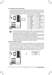
... MIC GND MIC Power NC Line Out (R) NC NC No Pin Line Out (L) NC F_PANEL (H61M-D2) DIP 1 23 1 DIP 1 23 1 DIP 1 23 1 BIOS Switcher (X58A-OC) DB_POR•T The front panel audio header supports HD audio by expansion caPrCdIse)pofowrerdciognintaecltoaru(SdAioTAo)(uXt5p8uAt-OfCro)m your chassis front panel audio module to certain...
... MIC GND MIC Power NC Line Out (R) NC NC No Pin Line Out (L) NC F_PANEL (H61M-D2) DIP 1 23 1 DIP 1 23 1 DIP 1 23 1 BIOS Switcher (X58A-OC) DB_POR•T The front panel audio header supports HD audio by expansion caPrCdIse)pofowrerdciognintaecltoaru(SdAioTAo)(uXt5p8uAt-OfCro)m your chassis front panel audio module to certain...
Manual
Page 34
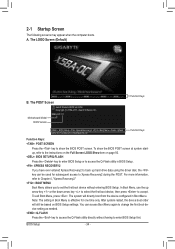
... utility in BIOS Setup. : XPRESS RECOVERY2 If you to set the first boot device without having to accept. BIOS Setup - 34 - Motherboard Model BIOS Version X58A-OC F1f . . . . : BIOS Setup : XpressRecovery2 : Boot Menu : Qflash 03/07/2011-X58-ICH10-7A89QG0TC-00 Function Keys Function Keys: : POST SCREEN Press the key to show...
... utility in BIOS Setup. : XPRESS RECOVERY2 If you to set the first boot device without having to accept. BIOS Setup - 34 - Motherboard Model BIOS Version X58A-OC F1f . . . . : BIOS Setup : XpressRecovery2 : Boot Menu : Qflash 03/07/2011-X58-ICH10-7A89QG0TC-00 Function Keys Function Keys: : POST SCREEN Press the key to show...

Manual
Page 56
... Health Status CPU Warning Temperature CPU FAN Fail Warning CPU Smart FAN Control x Slope PWM CPU Smart FAN Mode [Disabled] [Disabled] [Normal] 1.75 PWM value /oC [Auto] Item Help Menu Level Move Enter: Select F5: Previous Values +/-/PU/PD: Value F10: Save F6: Fail-Safe Defaults ESC: Exit F1: General...
... Health Status CPU Warning Temperature CPU FAN Fail Warning CPU Smart FAN Control x Slope PWM CPU Smart FAN Mode [Disabled] [Disabled] [Normal] 1.75 PWM value /oC [Auto] Item Help Menu Level Move Enter: Select F5: Previous Values +/-/PU/PD: Value F10: Save F6: Fail-Safe Defaults ESC: Exit F1: General...
Manual
Page 57
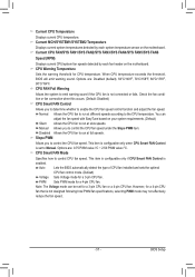
.../SYS FAN6 Speed (RPM) Displays current CPU/system fan speeds detected by each fan header on the motherboard. Options are : 0.75 PWM value /oC ~ 2.50 PWM value /oC. CPU FAN Fail Warning Allows the system to control CPU fan speed. Check the fan condition or fan connection when this occurs. (Default: Disabled...
.../SYS FAN6 Speed (RPM) Displays current CPU/system fan speeds detected by each fan header on the motherboard. Options are : 0.75 PWM value /oC ~ 2.50 PWM value /oC. CPU FAN Fail Warning Allows the system to control CPU fan speed. Check the fan condition or fan connection when this occurs. (Default: Disabled...
Manual
Page 68
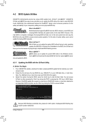
...system malfunction. Note: The USB flash drive or hard drive must use and allow you from the nearest @BIOS server 4-2-1 Updating the BIOS with caution. X58A-OC F1f . . . . : BIOS Setup : XpressRecovery2 : Boot Menu : Qflash 03/07/2011-X58-ICH10-7A89QG0TC-00 Because BIOS flashing is saved ... attached to your motherboard model. 2. Unique Features - 68 - For the sake of going through complicated BIOS flashing process. Restart the system. GIGABYTE Q-Flash and @BIOS are easy-to enter operating systems like MS-DOS or Window first. What is Q-Flash™? What is DualBIOS™?...
...system malfunction. Note: The USB flash drive or hard drive must use and allow you from the nearest @BIOS server 4-2-1 Updating the BIOS with caution. X58A-OC F1f . . . . : BIOS Setup : XpressRecovery2 : Boot Menu : Qflash 03/07/2011-X58-ICH10-7A89QG0TC-00 Because BIOS flashing is saved ... attached to your motherboard model. 2. Unique Features - 68 - For the sake of going through complicated BIOS flashing process. Restart the system. GIGABYTE Q-Flash and @BIOS are easy-to enter operating systems like MS-DOS or Window first. What is Q-Flash™? What is DualBIOS™?...
Manual
Page 80
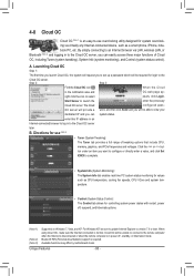
... , suspend, and hibernate options. (Note 1) (Note 2) (Note 3) Supported on Windows 7, Vista, and XP. When using Cloud OC, make sure the Internet connection is required. 4-8 Cloud OC Cloud OC (Note 1) is an easy-to-use (Note 3) • Tuner (System Tweaking): The Tuner tab provides a full range of Cloud...connect to the remote computer when the Internet is disconnected or when the remote computer is in to the Cloud OC server, you to the Cloud OC server. By simply connecting to an Internet browser via virtually any Internet-connected device, such as CPU temperature, cooling...
... , suspend, and hibernate options. (Note 1) (Note 2) (Note 3) Supported on Windows 7, Vista, and XP. When using Cloud OC, make sure the Internet connection is required. 4-8 Cloud OC Cloud OC (Note 1) is an easy-to-use (Note 3) • Tuner (System Tweaking): The Tuner tab provides a full range of Cloud...connect to the remote computer when the Internet is disconnected or when the remote computer is in to the Cloud OC server, you to the Cloud OC server. By simply connecting to an Internet browser via virtually any Internet-connected device, such as CPU temperature, cooling...

