
Manual
Page 1
... screen to the biggest drive in the Intel Chipset. (Note 2) It is recommended that before you run the X.H.D utility, back up all motherboard drivers, including the X.H.D utility. Using GIGABYTE eXtreme Hard Drive (X.H.D) Instructions:(Note 2) Before launching X.H.D, make sure the newly added harddrive has equal or greater capacity than the RAID-ready system...
... screen to the biggest drive in the Intel Chipset. (Note 2) It is recommended that before you run the X.H.D utility, back up all motherboard drivers, including the X.H.D utility. Using GIGABYTE eXtreme Hard Drive (X.H.D) Instructions:(Note 2) Before launching X.H.D, make sure the newly added harddrive has equal or greater capacity than the RAID-ready system...
Manual
Page 1
GA-Q57M-S2H LGA1156 socket motherboard for Intel® Core™ i7 processor family/ Intel® Core™ i5 processor family/ Intel® Core™ i3 processor family User's Manual Rev. 1002 12ME-Q57MS2H-1002R
GA-Q57M-S2H LGA1156 socket motherboard for Intel® Core™ i7 processor family/ Intel® Core™ i5 processor family/ Intel® Core™ i3 processor family User's Manual Rev. 1002 12ME-Q57MS2H-1002R
Manual
Page 2
Motherboard GA-Q57M-S2H Mar. 8, 2010 Motherboard GA-Q57M-S2H Mar. 8, 2010
Motherboard GA-Q57M-S2H Mar. 8, 2010 Motherboard GA-Q57M-S2H Mar. 8, 2010
Manual
Page 3
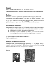
..., drivers, or when looking for technical information. For instructions on how to their respective owners. Check your motherboard looks like this manual may be made by any form or by GIGABYTE without GIGABYTE's prior written permission. Copyright © 2010 GIGA-BYTE TECHNOLOGY CO., LTD. Disclaimer Information in this : "REV: X.X." For detailed product information...
..., drivers, or when looking for technical information. For instructions on how to their respective owners. Check your motherboard looks like this manual may be made by any form or by GIGABYTE without GIGABYTE's prior written permission. Copyright © 2010 GIGA-BYTE TECHNOLOGY CO., LTD. Disclaimer Information in this : "REV: X.X." For detailed product information...
Manual
Page 4
Table of Contents Box Contents...6 Optional Items...6 GA-Q57M-S2H Motherboard Layout 7 GA-Q57M-S2H Motherboard Block Diagram 8 Chapter 1 Hardware Installation 9 1-1 Installation Precautions 9 1-2 Product Specifications 10 1-3 Installing the CPU and CPU Cooler 13 1-3-1 Installing the CPU 13 1-3-2 Installing the CPU Cooler ...
Table of Contents Box Contents...6 Optional Items...6 GA-Q57M-S2H Motherboard Layout 7 GA-Q57M-S2H Motherboard Block Diagram 8 Chapter 1 Hardware Installation 9 1-1 Installation Precautions 9 1-2 Product Specifications 10 1-3 Installing the CPU and CPU Cooler 13 1-3-1 Installing the CPU 13 1-3-2 Installing the CPU Cooler ...
Manual
Page 6
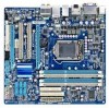
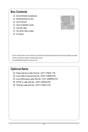
The box contents are for reference only. Box Contents GA-Q57M-S2H motherboard Motherboard driver disk User's Manual Quick Installation Guide One IDE cable Two SATA 3Gb/s cables I/O Shield • The box contents above are subject to change without notice. • The motherboard image is for reference only and the actual items shall depend on the product...
The box contents are for reference only. Box Contents GA-Q57M-S2H motherboard Motherboard driver disk User's Manual Quick Installation Guide One IDE cable Two SATA 3Gb/s cables I/O Shield • The box contents above are subject to change without notice. • The motherboard image is for reference only and the actual items shall depend on the product...
Manual
Page 7
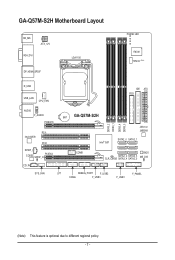
GA-Q57M-S2H Motherboard Layout KB_MS ATX_12V VGA_DVI DP_HDMI_SPDIF LGA1156 PHASE LED IT8720 TPM IC (Note) R_USB USB_LAN CPU_FAN IDE ATX FDD AUDIO F_AUDIO PCIEX16 PCI1 Intel 82578 PCI2 SPDIF_I CODEC SPDIF_O PCIEX4 CD_IN BAT GA-Q57M-S2H Intel® Q57 DDR3_2 DDR3_1 DDR3_4 DDR3_3 JMicron JMB368 SATA2_0 SATA2_1 COMB BIOS SATA2_2 SATA2_3 CLR_CMOS SATA2_4 SATA2_5 ME_DIS SYS_FAN LPT DEBUG_PORT F_USB2 F_PANEL COMA F_USB3 F_USB1 (Note) This feature is optional due to different regional policy. - 7 -
GA-Q57M-S2H Motherboard Layout KB_MS ATX_12V VGA_DVI DP_HDMI_SPDIF LGA1156 PHASE LED IT8720 TPM IC (Note) R_USB USB_LAN CPU_FAN IDE ATX FDD AUDIO F_AUDIO PCIEX16 PCI1 Intel 82578 PCI2 SPDIF_I CODEC SPDIF_O PCIEX4 CD_IN BAT GA-Q57M-S2H Intel® Q57 DDR3_2 DDR3_1 DDR3_4 DDR3_3 JMicron JMB368 SATA2_0 SATA2_1 COMB BIOS SATA2_2 SATA2_3 CLR_CMOS SATA2_4 SATA2_5 ME_DIS SYS_FAN LPT DEBUG_PORT F_USB2 F_PANEL COMA F_USB3 F_USB1 (Note) This feature is optional due to different regional policy. - 7 -
Manual
Page 8
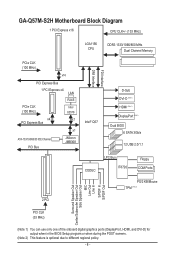
GA-Q57M-S2H Motherboard Block Diagram 1 PCI Express x16 CPU CLK+/- (133 MHz) LGA1156 CPU DDR3 1333/1066/800 MHz Dual Channel Memory PCIe CLK (100 MHz) x16 PCI ...
GA-Q57M-S2H Motherboard Block Diagram 1 PCI Express x16 CPU CLK+/- (133 MHz) LGA1156 CPU DDR3 1333/1066/800 MHz Dual Channel Memory PCIe CLK (100 MHz) x16 PCI ...
Manual
Page 9
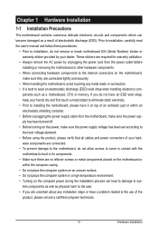
... for warranty validation. • Always remove the AC power by your dealer. Chapter 1 Hardware Installation 1-1 Installation Precautions The motherboard contains numerous delicate electronic circuits and components which can lead to damage to system components as well as physical harm to the ... It is best to the use of electrostatic discharge (ESD). These stickers are connected tightly and securely. • When handling the motherboard, avoid touching any installation steps or have a problem related to wear an electrostatic discharge (ESD) wrist strap when handling electronic com...
... for warranty validation. • Always remove the AC power by your dealer. Chapter 1 Hardware Installation 1-1 Installation Precautions The motherboard contains numerous delicate electronic circuits and components which can lead to damage to system components as well as physical harm to the ... It is best to the use of electrostatic discharge (ESD). These stickers are connected tightly and securely. • When handling the motherboard, avoid touching any installation steps or have a problem related to wear an electrostatic discharge (ESD) wrist strap when handling electronic com...
Manual
Page 12
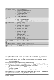
... 7) Whether the CPU fan speed control function is supported will depend on the CPU cooler you install. (Note 8) Available functions in EasyTune may differ by motherboard model.
... 7) Whether the CPU fan speed control function is supported will depend on the CPU cooler you install. (Note 8) Available functions in EasyTune may differ by motherboard model.
Manual
Page 13
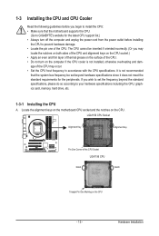
... support list.) • Always turn on the CPU. Locate the alignment keys on the motherboard CPU socket and the notches on the computer if the CPU cooler is not recommended that the motherboard supports the CPU. (Go to GIGABYTE's website for the peripherals. age of the CPU. 1-3 Installing the CPU and CPU Cooler...
... support list.) • Always turn on the CPU. Locate the alignment keys on the motherboard CPU socket and the notches on the computer if the CPU cooler is not recommended that the motherboard supports the CPU. (Go to GIGABYTE's website for the peripherals. age of the CPU. 1-3 Installing the CPU and CPU Cooler...
Manual
Page 14
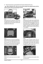
... from the socket with your thumb to lift up the front edge (next to the CPU. Step 5: Push the CPU socket lever back into the motherboard CPU socket. NOTE: Hold the CPU socket lever by the handle, not the lever base portion. To protect the CPU socket, always replace the protective...
... from the socket with your thumb to lift up the front edge (next to the CPU. Step 5: Push the CPU socket lever back into the motherboard CPU socket. NOTE: Hold the CPU socket lever by the handle, not the lever base portion. To protect the CPU socket, always replace the protective...
Manual
Page 15
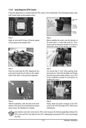
... CPU Cooler Follow the steps below to correctly install the CPU cooler on the motherboard. (The following procedure uses Intel® boxed cooler as the picture above shows...the CPU. Inadequately removing the CPU cooler may adhere to your CPU cooler installation manual for instructions on the motherboard. Step 2: Before installing the cooler, note the direction of the arrow sign on the male push pin. ...Female Push Pin Step 1: Apply an even and thin layer of thermal grease on the surface of the motherboard. Push down each push pin. If the push pin is to the CPU fan header (CPU_FAN) on ...
... CPU Cooler Follow the steps below to correctly install the CPU cooler on the motherboard. (The following procedure uses Intel® boxed cooler as the picture above shows...the CPU. Inadequately removing the CPU cooler may adhere to your CPU cooler installation manual for instructions on the motherboard. Step 2: Before installing the cooler, note the direction of the arrow sign on the male push pin. ...Female Push Pin Step 1: Apply an even and thin layer of thermal grease on the surface of the motherboard. Push down each push pin. If the push pin is to the CPU fan header (CPU_FAN) on ...
Manual
Page 16
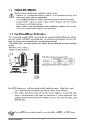
... . (Go to GIGABYTE's website for optimum performance. Hardware Installation - 16 - After the memory is installed, the BIOS will double the original memory bandwidth. When enabling Dual Channel mode with two or four memory modules, it in only one DDR3 memory module is recommended that the motherboard supports the memory. ..., DS=Double-Sided, "- -"=No Memory) DDR3_2 DDR3_1 DDR3_4 DDR3_3 Due to insert the memory, switch the direction. 1-4-1 Dual Channel Memory Configuration This motherboard provides four DDR3 memory sockets and supports Dual Channel Technology. It is installed. 2.
... . (Go to GIGABYTE's website for optimum performance. Hardware Installation - 16 - After the memory is installed, the BIOS will double the original memory bandwidth. When enabling Dual Channel mode with two or four memory modules, it in only one DDR3 memory module is recommended that the motherboard supports the memory. ..., DS=Double-Sided, "- -"=No Memory) DDR3_2 DDR3_1 DDR3_4 DDR3_3 Due to insert the memory, switch the direction. 1-4-1 Dual Channel Memory Configuration This motherboard provides four DDR3 memory sockets and supports Dual Channel Technology. It is installed. 2.
Manual
Page 17
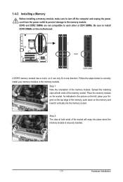
..., make sure to turn off the computer and unplug the power cord from the power outlet to prevent damage to install DDR3 DIMMs on this motherboard. DDR3 and DDR2 DIMMs are not compatible to each other or DDR DIMMs. Be sure to the memory module.
..., make sure to turn off the computer and unplug the power cord from the power outlet to prevent damage to install DDR3 DIMMs on this motherboard. DDR3 and DDR2 DIMMs are not compatible to each other or DDR DIMMs. Be sure to the memory module.
Manual
Page 18
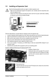
... the PCI Express slot. Remove the metal slot cover from the power outlet before you begin to install an expansion card: • Make sure the motherboard supports the expansion card. Install the driver provided with a screw. 5. Make sure the metal contacts on the top edge of the PCI Express slot to...
... the PCI Express slot. Remove the metal slot cover from the power outlet before you begin to install an expansion card: • Make sure the motherboard supports the expansion card. Install the driver provided with a screw. 5. Make sure the metal contacts on the top edge of the PCI Express slot to...
Manual
Page 21
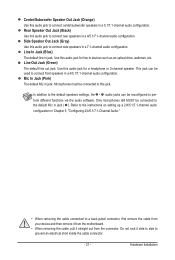
... default speakers settings, the ~ audio jacks can be connected to connect front speakers in a 4/5.1/7.1-channel audio configuration. Do not rock it straight out from the motherboard. • When removing the cable, pull it side to side to prevent an electrical short inside the cable connector. - 21 - Only microphones still MUST be...
... default speakers settings, the ~ audio jacks can be connected to connect front speakers in a 4/5.1/7.1-channel audio configuration. Do not rock it straight out from the motherboard. • When removing the cable, pull it side to side to prevent an electrical short inside the cable connector. - 21 - Only microphones still MUST be...
Manual
Page 22
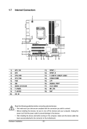
... 13) F_USB1/F_USB2/F_USB3 14) COMA/COMB 15) LPT 16) DEBUG_PORT 17) CLR_CMOS 18) ME_DIS 19) BAT Read the following guidelines before turning on the motherboard.
... 13) F_USB1/F_USB2/F_USB3 14) COMA/COMB 15) LPT 16) DEBUG_PORT 17) CLR_CMOS 18) ME_DIS 19) BAT Read the following guidelines before turning on the motherboard.
Manual
Page 23
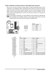
... possesses a foolproof design. Connect the power supply cable to the CPU. If the 12V power connector is turned off and all the components on the motherboard. Hardware Installation Before connecting the power connector, first make sure the power supply is not connected, the computer will not start. 1/2) ATX_12V/ATX (2x2 12V...
... possesses a foolproof design. Connect the power supply cable to the CPU. If the 12V power connector is turned off and all the components on the motherboard. Hardware Installation Before connecting the power connector, first make sure the power supply is not connected, the computer will not start. 1/2) ATX_12V/ATX (2x2 12V...
Manual
Page 24
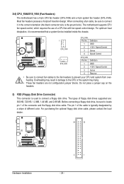
... possess a foolproof insertion design. The pin 1 of the cable is used to locate pin 1 of floppy disk drives supported are not configuration jumper blocks. The motherboard supports CPU fan speed control, which requires the use of different color. Overheating may hang. • These fan headers are : 360 KB, 720 KB, 1.2 MB... black connector wire is recommended that a system fan be sure to connect it is the ground wire). CPU_FAN: 1 Pin No. 3/4) CPU_FAN/SYS_FAN (Fan Headers) The motherboard has a 4-pin CPU fan header (CPU_FAN) and a 4-pin system fan header (SYS_FAN).
... possess a foolproof insertion design. The pin 1 of the cable is used to locate pin 1 of floppy disk drives supported are not configuration jumper blocks. The motherboard supports CPU fan speed control, which requires the use of different color. Overheating may hang. • These fan headers are : 360 KB, 720 KB, 1.2 MB... black connector wire is recommended that a system fan be sure to connect it is the ground wire). CPU_FAN: 1 Pin No. 3/4) CPU_FAN/SYS_FAN (Fan Headers) The motherboard has a 4-pin CPU fan header (CPU_FAN) and a 4-pin system fan header (SYS_FAN).


