User Manual
Page 2
Motherboard GA-P75-D3 Feb. 17, 2012 Motherboard GA-P75-D3 Feb. 17, 2012
Motherboard GA-P75-D3 Feb. 17, 2012 Motherboard GA-P75-D3 Feb. 17, 2012
User Manual
Page 3
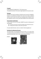
...in this manual may be made by GIGABYTE without GIGABYTE's prior written permission. For product-related information, check on our website at: http://www.gigabyte.com Identifying Your Motherboard Revision The revision number on your motherboard revision before updating motherboard BIOS, drivers, or when looking ...detailed product information, carefully read the User's Manual. For example, "REV: 1.0" means the revision of GIGABYTE. Check your motherboard looks like this manual are legally registered to their respective owners. Copyright © 2012 GIGA-BYTE TECHNOLOGY CO., LTD.
...in this manual may be made by GIGABYTE without GIGABYTE's prior written permission. For product-related information, check on our website at: http://www.gigabyte.com Identifying Your Motherboard Revision The revision number on your motherboard revision before updating motherboard BIOS, drivers, or when looking ...detailed product information, carefully read the User's Manual. For example, "REV: 1.0" means the revision of GIGABYTE. Check your motherboard looks like this manual are legally registered to their respective owners. Copyright © 2012 GIGA-BYTE TECHNOLOGY CO., LTD.
User Manual
Page 4
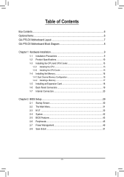
Table of Contents Box Contents...6 Optional Items...6 GA-P75-D3 Motherboard Layout 7 GA-P75-D3 Motherboard Block Diagram 8 Chapter 1 Hardware Installation 9 1-1 Installation Precautions 9 1-2 Product Specifications 10 1-3 Installing the CPU and CPU Cooler 13 1-3-1 Installing the CPU 13 1-3-2 Installing the CPU Cooler ...
Table of Contents Box Contents...6 Optional Items...6 GA-P75-D3 Motherboard Layout 7 GA-P75-D3 Motherboard Block Diagram 8 Chapter 1 Hardware Installation 9 1-1 Installation Precautions 9 1-2 Product Specifications 10 1-3 Installing the CPU and CPU Cooler 13 1-3-1 Installing the CPU 13 1-3-2 Installing the CPU Cooler ...
User Manual
Page 6
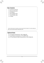
The box contents are for reference only and the actual items shall depend on the product package you obtain. Optional Items †† 2-port USB 2.0 bracket (Part No. 12CR1-1UB030-5*R) †† 2-port SATA power cable (Part No. 12CF1-2SERPW-0*R) †† 3.5" Front Panel with 2 USB 3.0/2.0 ports (Part No. 12CR1-FPX582-0*R) - 6 - Box Contents 55 GA-P75-D3 motherboard 55 Motherboard driver disk 55 User's Manual 55 Quick Installation Guide 55 Two SATA 6Gb/s cables 55 I/O Shield The box contents above are subject to change without notice.
The box contents are for reference only and the actual items shall depend on the product package you obtain. Optional Items †† 2-port USB 2.0 bracket (Part No. 12CR1-1UB030-5*R) †† 2-port SATA power cable (Part No. 12CF1-2SERPW-0*R) †† 3.5" Front Panel with 2 USB 3.0/2.0 ports (Part No. 12CR1-FPX582-0*R) - 6 - Box Contents 55 GA-P75-D3 motherboard 55 Motherboard driver disk 55 User's Manual 55 Quick Installation Guide 55 Two SATA 6Gb/s cables 55 I/O Shield The box contents above are subject to change without notice.
User Manual
Page 8
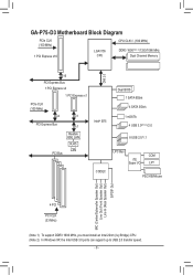
GA-P75-D3 Motherboard Block Diagram PCIe CLK (100 MHz) 1 PCI Express x16 LGA1155 CPU CPU CLK+/- (100 MHz) DDR3 1600(Note 1)/1333/1066 MHz Dual Channel Memory DMI 2.0 ...
GA-P75-D3 Motherboard Block Diagram PCIe CLK (100 MHz) 1 PCI Express x16 LGA1155 CPU CPU CLK+/- (100 MHz) DDR3 1600(Note 1)/1333/1066 MHz Dual Channel Memory DMI 2.0 ...
User Manual
Page 9
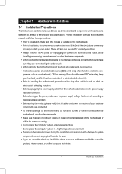
...ed computer technician. - 9 - Hardware Installation ponents such as a result of your dealer. Chapter 1 Hardware Installation 1-1 Installation Precautions The motherboard contains numerous delicate electronic circuits and components which can lead to damage to system components as well as physical harm to the user. &#..., keep your hands dry and first touch a metal object to eliminate static electricity. • Prior to installing the motherboard, please have a problem related to the local voltage standard. • Before using the product, please verify that all cables ...
...ed computer technician. - 9 - Hardware Installation ponents such as a result of your dealer. Chapter 1 Hardware Installation 1-1 Installation Precautions The motherboard contains numerous delicate electronic circuits and components which can lead to damage to system components as well as physical harm to the user. &#..., keep your hands dry and first touch a metal object to eliminate static electricity. • Prior to installing the motherboard, please have a problem related to the local voltage standard. • Before using the product, please verify that all cables ...
User Manual
Page 13
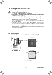
... card, memory, hard drive, etc. 1-3-1 Installing the CPU A. Locate the alignment keys on the motherboard CPU socket and the notches on the computer if the CPU cooler is not recommended that the motherboard supports the CPU. (Go to GIGABYTE's website for the peripherals. Hardware Installation age of the CPU may locate the notches...
... card, memory, hard drive, etc. 1-3-1 Installing the CPU A. Locate the alignment keys on the motherboard CPU socket and the notches on the computer if the CPU cooler is not recommended that the motherboard supports the CPU. (Go to GIGABYTE's website for the peripherals. Hardware Installation age of the CPU may locate the notches...
User Manual
Page 14
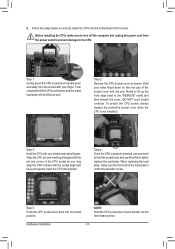
... edge (next to lightly replace the load plate. Step 2: Remove the CPU socket cover as well. Step 5: Push the CPU socket lever back into the motherboard CPU socket. Align the CPU pin one marking (triangle) with the pin one hand to hold the socket lever and use your finger. NOTE...
... edge (next to lightly replace the load plate. Step 2: Remove the CPU socket cover as well. Step 5: Push the CPU socket lever back into the motherboard CPU socket. Align the CPU pin one marking (triangle) with the pin one hand to hold the socket lever and use your finger. NOTE...
User Manual
Page 15
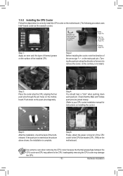
...) on the push pins diagonally. Hardware Installation 1-3-2 Installing the CPU Cooler Follow the steps below to correctly install the CPU cooler on the motherboard. (The following procedure uses Intel® boxed cooler as the picture above shows, the installation is to install.) Step 3: Place the cooler... for instructions on the surface of arrow is to the CPU. Step 4: You should hear a "click" when pushing down on the motherboard. Inadequately removing the CPU cooler may adhere to remove the cooler, on the contrary, is complete. Use extreme care when removing the CPU...
...) on the push pins diagonally. Hardware Installation 1-3-2 Installing the CPU Cooler Follow the steps below to correctly install the CPU cooler on the motherboard. (The following procedure uses Intel® boxed cooler as the picture above shows, the installation is to install.) Step 3: Place the cooler... for instructions on the surface of arrow is to the CPU. Step 4: You should hear a "click" when pushing down on the motherboard. Inadequately removing the CPU cooler may adhere to remove the cooler, on the contrary, is complete. Use extreme care when removing the CPU...
User Manual
Page 16
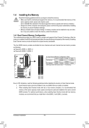
... mode. 1. The four DDR3 memory sockets are unable to insert the memory, switch the direction. 1-4-1 Dual Channel Memory Configuration This motherboard provides four DDR3 memory sockets and supports Dual Channel Technology. DS/SS - - Enabling Dual Channel memory mode will automatically detect the specifi... to install the memory: • Make sure that memory of the same capacity, brand, speed, and chips be used . (Go to GIGABYTE's website for the latest supported memory speeds and memory modules.) • Always turn off the computer and unplug the power cord from the power...
... mode. 1. The four DDR3 memory sockets are unable to insert the memory, switch the direction. 1-4-1 Dual Channel Memory Configuration This motherboard provides four DDR3 memory sockets and supports Dual Channel Technology. DS/SS - - Enabling Dual Channel memory mode will automatically detect the specifi... to install the memory: • Make sure that memory of the same capacity, brand, speed, and chips be used . (Go to GIGABYTE's website for the latest supported memory speeds and memory modules.) • Always turn off the computer and unplug the power cord from the power...
User Manual
Page 17
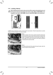
..., make sure to turn off the computer and unplug the power cord from the power outlet to prevent damage to install DDR3 DIMMs on this motherboard. Hardware Installation DDR3 and DDR2 DIMMs are not compatible to each other or DDR DIMMs. Be sure to the memory module. Step 1: Note the orientation...
..., make sure to turn off the computer and unplug the power cord from the power outlet to prevent damage to install DDR3 DIMMs on this motherboard. Hardware Installation DDR3 and DDR2 DIMMs are not compatible to each other or DDR DIMMs. Be sure to the memory module. Step 1: Note the orientation...
User Manual
Page 18
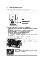
... back panel with the expansion card in the expansion slot. 1. If necessary, go to BIOS Setup to install an expansion card: • Make sure the motherboard supports the expansion card. Install the driver provided with a screw. 5. Make sure the card is fully inserted into the slot. 4. PCI Express x1 Slot PCI...
... back panel with the expansion card in the expansion slot. 1. If necessary, go to BIOS Setup to install an expansion card: • Make sure the motherboard supports the expansion card. Install the driver provided with a screw. 5. Make sure the card is fully inserted into the slot. 4. PCI Express x1 Slot PCI...
User Manual
Page 19
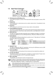
Coaxial S/PDIF Out Connector This connector provides digital audio out to an external audio system that your device and then remove it from the motherboard. • When removing the cable, pull it side to side to 1 Gbps data rate. Mic In Jack (Pink) The default Mic in jack. Refer to ...
Coaxial S/PDIF Out Connector This connector provides digital audio out to an external audio system that your device and then remove it from the motherboard. • When removing the cable, pull it side to side to 1 Gbps data rate. Mic In Jack (Pink) The default Mic in jack. Refer to ...
User Manual
Page 20
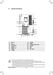
... devices and your devices are compliant with the connectors you wish to connect. • Before installing the devices, be sure to the connector on the motherboard. 1-7 Internal Connectors 1 4 3 2 4 12 7 5 6 14 9 15 10 4 13 11 8 1) ATX_12V 2) ATX 3) CPU_FAN 4) SYS_FAN1/2/3 5) SATA3 0 6) SATA2 1/2/3/4 7) mSATA 8) F_PANEL 9) F_AUDIO 10) SPDIF_O 11) F_USB1/F_USB2/F_USB3 12) F_USB30...
... devices and your devices are compliant with the connectors you wish to connect. • Before installing the devices, be sure to the connector on the motherboard. 1-7 Internal Connectors 1 4 3 2 4 12 7 5 6 14 9 15 10 4 13 11 8 1) ATX_12V 2) ATX 3) CPU_FAN 4) SYS_FAN1/2/3 5) SATA3 0 6) SATA2 1/2/3/4 7) mSATA 8) F_PANEL 9) F_AUDIO 10) SPDIF_O 11) F_USB1/F_USB2/F_USB3 12) F_USB30...
User Manual
Page 21
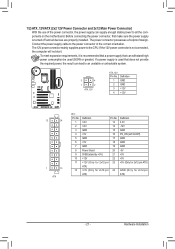
..., the result can supply enough stable power to all devices are properly installed. If a power supply is turned off and all the components on the motherboard. Before connecting the power connector, first make sure the power supply is used (500W or greater). 1/2) ATX_12V/ATX (2x2 12V Power Connector and 2x12...
..., the result can supply enough stable power to all devices are properly installed. If a power supply is turned off and all the components on the motherboard. Before connecting the power connector, first make sure the power supply is used (500W or greater). 1/2) ATX_12V/ATX (2x2 12V Power Connector and 2x12...
User Manual
Page 22
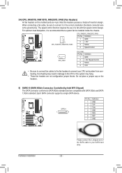
... is recommended that a system fan be sure to connect it in damage to prevent your SATA hard drive. Do not place a jumper cap on this motherboard are not configuration jumper blocks. Most fan headers possess a foolproof insertion design. The speed control function requires the use of the SATA cable...
... is recommended that a system fan be sure to connect it in damage to prevent your SATA hard drive. Do not place a jumper cap on this motherboard are not configuration jumper blocks. Most fan headers possess a foolproof insertion design. The speed control function requires the use of the SATA cable...
User Manual
Page 25
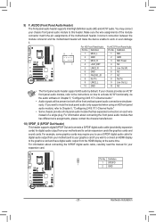
... "Configuring 2/4/5.1/7.1-Channel Audio." Hardware Installation Incorrect connection between the module connector and the motherboard header will be present on each wire(GA-IVB) instead of the motherboard header. If your chassis front panel audio module to certain expansion cards like graphics cards and...(GA-IVB) sound cards. 9) F_AUDIO (Front Panel Audio Header) The front panel audio header supports Intel ...
... "Configuring 2/4/5.1/7.1-Channel Audio." Hardware Installation Incorrect connection between the module connector and the motherboard header will be present on each wire(GA-IVB) instead of the motherboard header. If your chassis front panel audio module to certain expansion cards like graphics cards and...(GA-IVB) sound cards. 9) F_AUDIO (Front Panel Audio Header) The front panel audio header supports Intel ...
User Manual
Page 29
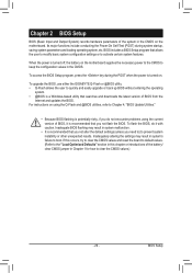
...turned off, the battery on using the current version of BIOS from the Internet and updates the BIOS. To upgrade the BIOS, use either the GIGABYTE Q-Flash or @BIOS utility. • Q-Flash allows the user to keep the configuration values in the CMOS. To access the ... or introductions of the system in the CMOS on . Inadequately altering the settings may result in system malfunction. • It is turned on the motherboard. Inadequate BIOS flashing may result in system's failure to clear the CMOS values.) - 29 - Its major functions include conducting the Power-On...
...turned off, the battery on using the current version of BIOS from the Internet and updates the BIOS. To upgrade the BIOS, use either the GIGABYTE Q-Flash or @BIOS utility. • Q-Flash allows the user to keep the configuration values in the CMOS. To access the ... or introductions of the system in the CMOS on . Inadequately altering the settings may result in system malfunction. • It is turned on the motherboard. Inadequate BIOS flashing may result in system's failure to clear the CMOS values.) - 29 - Its major functions include conducting the Power-On...
User Manual
Page 40
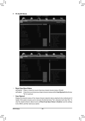
... restart your system. BIOS Setup - 40 - To clear the chassis intrusion status record, set Reset Case Open Status to Enabled, save the settings to the motherboard CI header. If the system chassis cover is removed, this field will show "Yes", otherwise it will show "No".
... restart your system. BIOS Setup - 40 - To clear the chassis intrusion status record, set Reset Case Open Status to Enabled, save the settings to the motherboard CI header. If the system chassis cover is removed, this field will show "Yes", otherwise it will show "No".
User Manual
Page 42
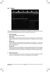
..., minute, and second. 2-4 System This section provides information on the device connected to all . ` ATA Port Information This section provides information on your CPU, memory, motherboard model, and BIOS version. the User level only allows you to make changes to certain BIOS settings but not all BIOS settings; BIOS Setup - 42...
..., minute, and second. 2-4 System This section provides information on the device connected to all . ` ATA Port Information This section provides information on your CPU, memory, motherboard model, and BIOS version. the User level only allows you to make changes to certain BIOS settings but not all BIOS settings; BIOS Setup - 42...


