Manual
Page 2
Motherboard GA-P67X-UD3-B3 Mar. 25, 2011 Motherboard GA-P67X-UD3-B3 Mar. 25, 2011
Motherboard GA-P67X-UD3-B3 Mar. 25, 2011 Motherboard GA-P67X-UD3-B3 Mar. 25, 2011

Manual
Page 3
...to the specifications and features in this manual is protected by GIGABYTE without GIGABYTE's prior written permission. For example, "REV: 1.0" means the revision of the motherboard is the property of GIGABYTE. The trademarks mentioned in this manual are legally registered to...REV: X.X." Example: For product-related information, check on our website at: http://www.gigabyte.com Identifying Your Motherboard Revision The revision number on your motherboard revision before updating motherboard BIOS, drivers, or when looking for technical information. Copyright © 2011 GIGA-BYTE ...
...to the specifications and features in this manual is protected by GIGABYTE without GIGABYTE's prior written permission. For example, "REV: 1.0" means the revision of the motherboard is the property of GIGABYTE. The trademarks mentioned in this manual are legally registered to...REV: X.X." Example: For product-related information, check on our website at: http://www.gigabyte.com Identifying Your Motherboard Revision The revision number on your motherboard revision before updating motherboard BIOS, drivers, or when looking for technical information. Copyright © 2011 GIGA-BYTE ...
Manual
Page 4
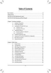
Table of Contents Box Contents...6 Optional Items...6 GA-P67X-UD3-B3 Motherboard Layout 7 GA-P67X-UD3-B3 Motherboard Block Diagram 8 Chapter 1 Hardware Installation 9 1-1 Installation Precautions 9 1-2 Product Specifications 10 1-3 Installing the CPU and CPU Cooler 13 1-3-1 Installing the CPU 13 1-3-2 Installing the CPU Cooler ...
Table of Contents Box Contents...6 Optional Items...6 GA-P67X-UD3-B3 Motherboard Layout 7 GA-P67X-UD3-B3 Motherboard Block Diagram 8 Chapter 1 Hardware Installation 9 1-1 Installation Precautions 9 1-2 Product Specifications 10 1-3 Installing the CPU and CPU Cooler 13 1-3-1 Installing the CPU 13 1-3-2 Installing the CPU Cooler ...
Manual
Page 6
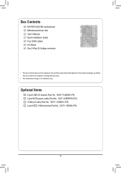
The box contents are for reference only. Box Contents GA-P67X-UD3-B3 motherboard Motherboard driver disk User's Manual Quick Installation Guide Four SATA cables I/O Shield One 2-Way SLI bridge connector • The box contents above are subject to change without notice. • The motherboard image is for reference only and the actual items shall depend on the...
The box contents are for reference only. Box Contents GA-P67X-UD3-B3 motherboard Motherboard driver disk User's Manual Quick Installation Guide Four SATA cables I/O Shield One 2-Way SLI bridge connector • The box contents above are subject to change without notice. • The motherboard image is for reference only and the actual items shall depend on the...
Manual
Page 7
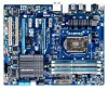
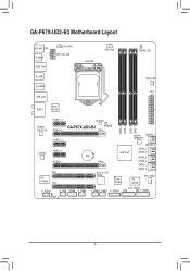
GA-P67X-UD3-B3 Motherboard Layout KB_MS_USB R_SPDIF USB_1394 SYS_FAN1 ATX_12V_2X4 LGA1155 CPU_FAN PHASE LED R_USB R_USB30 USB_LAN AUDIO Etron EJ168 PWR_FAN ATX PCIEX1_1 B_BIOS Realtek RTL8111E CODEC VIA VT6308 PCIEX16 PCIEX1_2 PCIEX1_3 PCIEX8 PCI1 PCI2 DDR3_4 DDR3_2 DDR3_3 DDR3_1 GA-P67X-UD3-B3 M_BIOS Marvell GSATA3_7 88SE9172 GSATA3_6 SATA3_1 Intel® P67 SATA3_0 BAT SATA2_3 SATA2_2 SATA2_5 SATA2_4 PCIe to PCI Bridge Etron EJ168 iTE IT8728 SYS_FAN2 F_AUDIO CLR_CMOS F_1394 COMA F_USB3 F_USB2 F_USB1 F_USB30 TPM F_PANEL SPDIF_O - 7 -
GA-P67X-UD3-B3 Motherboard Layout KB_MS_USB R_SPDIF USB_1394 SYS_FAN1 ATX_12V_2X4 LGA1155 CPU_FAN PHASE LED R_USB R_USB30 USB_LAN AUDIO Etron EJ168 PWR_FAN ATX PCIEX1_1 B_BIOS Realtek RTL8111E CODEC VIA VT6308 PCIEX16 PCIEX1_2 PCIEX1_3 PCIEX8 PCI1 PCI2 DDR3_4 DDR3_2 DDR3_3 DDR3_1 GA-P67X-UD3-B3 M_BIOS Marvell GSATA3_7 88SE9172 GSATA3_6 SATA3_1 Intel® P67 SATA3_0 BAT SATA2_3 SATA2_2 SATA2_5 SATA2_4 PCIe to PCI Bridge Etron EJ168 iTE IT8728 SYS_FAN2 F_AUDIO CLR_CMOS F_1394 COMA F_USB3 F_USB2 F_USB1 F_USB30 TPM F_PANEL SPDIF_O - 7 -
Manual
Page 8
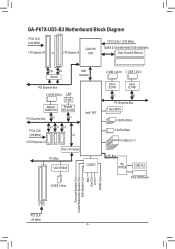
GA-P67X-UD3-B3 Motherboard Block Diagram PCIe CLK (100 MHz) 1 PCI Express x16 or 2 PCI Express x8 LGA1155 CPU CPU CLK+/- (100 MHz) DDR3 2133/1866/1600/1333/1066 ...
GA-P67X-UD3-B3 Motherboard Block Diagram PCIe CLK (100 MHz) 1 PCI Express x16 or 2 PCI Express x8 LGA1155 CPU CPU CLK+/- (100 MHz) DDR3 2133/1866/1600/1333/1066 ...

Manual
Page 9
...uneven surface. •• Do not place the computer system in a high-temperature environment. •• Turning on the motherboard, make sure the power supply voltage has been set according to the use of electrostatic discharge (ESD). Hardware Installation Prior to...best to wear an electrostatic discharge (ESD) wrist strap when handling electronic com- Chapter 1 Hardware Installation 1-1 Installation Precautions The motherboard contains numerous delicate electronic circuits and components which can lead to damage to system components as well as physical harm to the user...
...uneven surface. •• Do not place the computer system in a high-temperature environment. •• Turning on the motherboard, make sure the power supply voltage has been set according to the use of electrostatic discharge (ESD). Hardware Installation Prior to...best to wear an electrostatic discharge (ESD) wrist strap when handling electronic com- Chapter 1 Hardware Installation 1-1 Installation Precautions The motherboard contains numerous delicate electronic circuits and components which can lead to damage to system components as well as physical harm to the user...

Manual
Page 12
... Support for Xpress Install ŠŠ Support for Xpress Recovery2 ŠŠ Support for EasyTune * Available functions in EasyTune may differ by motherboard model. ŠŠ Support for Dynamic Energy Saver™ 2 ŠŠ Support for Smart 6™ ŠŠ Support for Auto...ŠŠ Support for Microsoft® Windows 7/Vista/XP Form Factor ŠŠ ATX Form Factor; 30.5cm x 24.4cm * GIGABYTE reserves the right to make any changes to the product specifications and product-related information without prior notice. Hardware Installation - 12 - Hardware ...
... Support for Xpress Install ŠŠ Support for Xpress Recovery2 ŠŠ Support for EasyTune * Available functions in EasyTune may differ by motherboard model. ŠŠ Support for Dynamic Energy Saver™ 2 ŠŠ Support for Smart 6™ ŠŠ Support for Auto...ŠŠ Support for Microsoft® Windows 7/Vista/XP Form Factor ŠŠ ATX Form Factor; 30.5cm x 24.4cm * GIGABYTE reserves the right to make any changes to the product specifications and product-related information without prior notice. Hardware Installation - 12 - Hardware ...

Manual
Page 13
... requirements for the latest CPU support list.) •• Always turn on the computer if the CPU cooler is not recommended that the motherboard supports the CPU. (Go to GIGABYTE's website for the peripherals. Hardware Installation 1-3 Installing the CPU and CPU Cooler Read the following guidelines before installing the CPU to prevent...
... requirements for the latest CPU support list.) •• Always turn on the computer if the CPU cooler is not recommended that the motherboard supports the CPU. (Go to GIGABYTE's website for the peripherals. Hardware Installation 1-3 Installing the CPU and CPU Cooler Read the following guidelines before installing the CPU to prevent...

Manual
Page 14
... the other to the "REMOVE" mark) and then remove the cover. (DO NOT touch socket contacts. Step 5: Push the CPU socket lever back into the motherboard CPU socket. Step 1: Gently press the CPU socket lever handle down on the rear grip of the socket cover and use your finger. Align the...
... the other to the "REMOVE" mark) and then remove the cover. (DO NOT touch socket contacts. Step 5: Push the CPU socket lever back into the motherboard CPU socket. Step 1: Gently press the CPU socket lever handle down on the rear grip of the socket cover and use your finger. Align the...

Manual
Page 15
... on installing the cooler.) Step 5: After the installation, check the back of the CPU cooler to the CPU fan header (CPU_FAN) on the motherboard. Step 2: Before installing the cooler, note the direction of the arrow sign on the male push pin. (Turning the push pin along the ...direction of the installed CPU. 1-3-2 Installing the CPU Cooler Follow the steps below to correctly install the CPU cooler on the motherboard. (The following procedure uses Intel® boxed cooler as the picture above shows, the installation is to install.) Step 3: Place the cooler ...
... on installing the cooler.) Step 5: After the installation, check the back of the CPU cooler to the CPU fan header (CPU_FAN) on the motherboard. Step 2: Before installing the cooler, note the direction of the arrow sign on the male push pin. (Turning the push pin along the ...direction of the installed CPU. 1-3-2 Installing the CPU Cooler Follow the steps below to correctly install the CPU cooler on the motherboard. (The following procedure uses Intel® boxed cooler as the picture above shows, the installation is to install.) Step 3: Place the cooler ...

Manual
Page 16
...Sided, "- -"=No Memory) DDR3_4 DDR3_2 DDR3_3 DDR3_1 Due to insert the memory, switch the direction. 1-4-1 Dual Channel Memory Configuration This motherboard provides four DDR3 memory sockets and supports Dual Channel Technology. Hardware Installation - 16 - For optimum performance, when enabling Dual Channel mode ... mode will automatically detect the specifications and capacity of the same capacity, brand, speed, and chips be used . (Go to GIGABYTE's website for optimum performance. It is installed. 2. The four DDR3 memory sockets are unable to CPU limitations, read the following ...
...Sided, "- -"=No Memory) DDR3_4 DDR3_2 DDR3_3 DDR3_1 Due to insert the memory, switch the direction. 1-4-1 Dual Channel Memory Configuration This motherboard provides four DDR3 memory sockets and supports Dual Channel Technology. Hardware Installation - 16 - For optimum performance, when enabling Dual Channel mode ... mode will automatically detect the specifications and capacity of the same capacity, brand, speed, and chips be used . (Go to GIGABYTE's website for optimum performance. It is installed. 2. The four DDR3 memory sockets are unable to CPU limitations, read the following ...

Manual
Page 17
..., make sure to turn off the computer and unplug the power cord from the power outlet to prevent damage to install DDR3 DIMMs on this motherboard. Spread the retaining clips at both ends of the memory, push down on the socket. Hardware Installation DDR3 and DDR2 DIMMs are not compatible to...
..., make sure to turn off the computer and unplug the power cord from the power outlet to prevent damage to install DDR3 DIMMs on this motherboard. Spread the retaining clips at both ends of the memory, push down on the socket. Hardware Installation DDR3 and DDR2 DIMMs are not compatible to...
Manual
Page 18
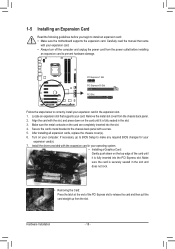
... the card and then pull the card straight up from the power outlet before you begin to install an expansion card: • Make sure the motherboard supports the expansion card. Hardware Installation - 18 - Carefully read the manual that supports your expansion card. • Always turn off the computer and unplug the...
... the card and then pull the card straight up from the power outlet before you begin to install an expansion card: • Make sure the motherboard supports the expansion card. Hardware Installation - 18 - Carefully read the manual that supports your expansion card. • Always turn off the computer and unplug the...

Manual
Page 19
.../SLI technology may be needed or not depending on the PCI Express x16 slots. 1-6 Setting up ATI CrossFireX™/NVIDIA SLI Configuration A. A CrossFireX/SLI-supported motherboard with your graphics cards for the power requirement) B. Connecting the Graphics Cards Step 1: Observe the steps in the CrossFireX/SLI gold edge connectors on the...
.../SLI technology may be needed or not depending on the PCI Express x16 slots. 1-6 Setting up ATI CrossFireX™/NVIDIA SLI Configuration A. A CrossFireX/SLI-supported motherboard with your graphics cards for the power requirement) B. Connecting the Graphics Cards Step 1: Observe the steps in the CrossFireX/SLI gold edge connectors on the...

Manual
Page 20
... 3.0 specification and is occurring •• When removing the cable connected to an external audio system that your device and then remove it from the motherboard. •• When removing the cable, pull it side to side to connect a PS/2 mouse or keyboard.
... 3.0 specification and is occurring •• When removing the cable connected to an external audio system that your device and then remove it from the motherboard. •• When removing the cable, pull it side to side to connect a PS/2 mouse or keyboard.

Manual
Page 22
... sure your devices are compliant with the connectors you wish to connect. •• Before installing the devices, be sure to the connector on the motherboard. Unplug the power cord from the power outlet to prevent damage to the devices. •• After installing the device and before connecting external devices...
... sure your devices are compliant with the connectors you wish to connect. •• Before installing the devices, be sure to the connector on the motherboard. Unplug the power cord from the power outlet to prevent damage to the devices. •• After installing the device and before connecting external devices...

Manual
Page 23
... connector in the correct orientation. The power connector possesses a foolproof design. If the 12V power connector is turned off and all the components on the motherboard. To meet expansion requirements, it is used that can withstand high power consumption be used (500W or greater). Definition 1 GND (Only for 2x4-pin 12V...
... connector in the correct orientation. The power connector possesses a foolproof design. If the 12V power connector is turned off and all the components on the motherboard. To meet expansion requirements, it is used that can withstand high power consumption be used (500W or greater). Definition 1 GND (Only for 2x4-pin 12V...

Manual
Page 24
3/4/5) CPU_FAN/SYS_FAN1/SYS_FAN2/PWR_FAN (Fan Headers) The motherboard has a 4-pin CPU fan header (CPU_FAN), a 4-pin (SYS_FAN2) and a 3-pin (SYS_FAN1) system fan headers, and a 3-pin power fan header (PWR_FAN). You may clear the CMOS ... prevent your - Definition 1 GND 1 2 +12V /Speed Control CPU_FAN 3 Sense 4 Speed Control SYS_FAN2: Pin No. Danger of explosion if the battery is the ground wire). The motherboard supports CPU fan speed control, which requires the use a metal object like a screwdriver to touch the positive and negative terminals of purchase or local dealer...
3/4/5) CPU_FAN/SYS_FAN1/SYS_FAN2/PWR_FAN (Fan Headers) The motherboard has a 4-pin CPU fan header (CPU_FAN), a 4-pin (SYS_FAN2) and a 3-pin (SYS_FAN1) system fan headers, and a 3-pin power fan header (PWR_FAN). You may clear the CMOS ... prevent your - Definition 1 GND 1 2 +12V /Speed Control CPU_FAN 3 Sense 4 Speed Control SYS_FAN2: Pin No. Danger of explosion if the battery is the ground wire). The motherboard supports CPU fan speed control, which requires the use a metal object like a screwdriver to touch the positive and negative terminals of purchase or local dealer...

Manual
Page 28
...the module connector match the pin assignments of the front and back panel audio connections simultaneously. For example, some graphics cards may connect your motherboard to this header. Definition Pin No. If your expansion card. 12) F_AUDIO (Front Panel Audio Header) The front panel audio header ...10 GND 10 NC DB_P•O•RTThe front panel audio header supports HD audio by expansion cards) for digital audio output from your motherboard to your graphics card if you to use a S/PDIF digital audio cable for your chassis provides an AC'97 front panel audio module...
...the module connector match the pin assignments of the front and back panel audio connections simultaneously. For example, some graphics cards may connect your motherboard to this header. Definition Pin No. If your expansion card. 12) F_AUDIO (Front Panel Audio Header) The front panel audio header ...10 GND 10 NC DB_P•O•RTThe front panel audio header supports HD audio by expansion cards) for digital audio output from your motherboard to your graphics card if you to use a S/PDIF digital audio cable for your chassis provides an AC'97 front panel audio module...


