Manual
Page 1
GA-P67A-UD5 LGA1155 socket motherboard for Intel® Core™ i7 processors/ Intel® Core™ i5 processors/ Intel® Core™ i3 processors/ Intel® Pentium® processors/ Intel® Celeron® processors User's Manual Rev. 1001 12ME-P67AUD5-1001R
GA-P67A-UD5 LGA1155 socket motherboard for Intel® Core™ i7 processors/ Intel® Core™ i5 processors/ Intel® Core™ i3 processors/ Intel® Pentium® processors/ Intel® Celeron® processors User's Manual Rev. 1001 12ME-P67AUD5-1001R

Manual
Page 2
Motherboard GA-P67A-UD5 Nov. 8, 2010 Motherboard GA-P67A-UD5 Nov. 8, 2010
Motherboard GA-P67A-UD5 Nov. 8, 2010 Motherboard GA-P67A-UD5 Nov. 8, 2010

Manual
Page 3
... product-related information, check on our website at: http://www.gigabyte.com Identifying Your Motherboard Revision The revision number on your motherboard revision before updating motherboard BIOS, drivers, or when looking for technical information. Example: No part of the motherboard is protected by GIGABYTE without GIGABYTE's prior written permission. Disclaimer Information in any form or by any...
... product-related information, check on our website at: http://www.gigabyte.com Identifying Your Motherboard Revision The revision number on your motherboard revision before updating motherboard BIOS, drivers, or when looking for technical information. Example: No part of the motherboard is protected by GIGABYTE without GIGABYTE's prior written permission. Disclaimer Information in any form or by any...

Manual
Page 4
Table of Contents Box Contents...6 Optional Items...6 GA-P67A-UD5 Motherboard Layout 7 GA-P67A-UD5 Motherboard Block Diagram 8 Chapter 1 Hardware Installation 9 1-1 Installation Precautions 9 1-2 Product Specifications 10 1-3 Installing the CPU and CPU Cooler 13 1-3-1 Installing the CPU 13 1-3-2 Installing the CPU Cooler ...
Table of Contents Box Contents...6 Optional Items...6 GA-P67A-UD5 Motherboard Layout 7 GA-P67A-UD5 Motherboard Block Diagram 8 Chapter 1 Hardware Installation 9 1-1 Installation Precautions 9 1-2 Product Specifications 10 1-3 Installing the CPU and CPU Cooler 13 1-3-1 Installing the CPU 13 1-3-2 Installing the CPU Cooler ...

Manual
Page 6
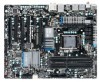
Optional Items 2-port USB 2.0 bracket (Part No. 12CR1-1UB030-5*R) 2-port IEEE 1394a bracket (Part No. 12CF1-1IE008-0*R) 2-port SATA power cable (Part No. 12CF1-2SERPW-0*R) - 6 - The box contents are for reference only. Box Contents GA-P67A-UD5 motherboard Motherboard driver disk User's Manual Quick Installation Guide Four SATA cables I/O Shield One 2-Way SLI bridge connector • The box contents above are subject to change without notice. • The motherboard image is for reference only and the actual items shall depend on the product package you obtain.
Optional Items 2-port USB 2.0 bracket (Part No. 12CR1-1UB030-5*R) 2-port IEEE 1394a bracket (Part No. 12CF1-1IE008-0*R) 2-port SATA power cable (Part No. 12CF1-2SERPW-0*R) - 6 - The box contents are for reference only. Box Contents GA-P67A-UD5 motherboard Motherboard driver disk User's Manual Quick Installation Guide Four SATA cables I/O Shield One 2-Way SLI bridge connector • The box contents above are subject to change without notice. • The motherboard image is for reference only and the actual items shall depend on the product package you obtain.

Manual
Page 7
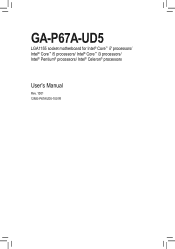
GA-P67A-UD5 Motherboard Layout KB_MS_USB SYS_FAN1 CPU_FAN R_SPDIF ATX_12V_2X USB_1394_ESATA_2 Marvell 88SE9128 USB_1394_ESATA_1 USB30 CPU_LED LGA1155 PW_SW PHASE LED PWR_FAN RST_SW CMOS_SW USB30_LAN AUDIO Realtek RTL8111E F_AUDIO VLI VL810 GD2 PCIEX1_1 (Note) PE1_LED GD1 PCIEX16 PE_LED DDR3_1 DDR3_2 DDR3_3 DDR3_4 DIMM_LED ATX BAT Renesas D720200 PCIEX1_2 PCI1 CODEC SPDIF_O PCIEX8 GA-P67A-UD5 PCI_LED iTE IT8892 Bridge...
GA-P67A-UD5 Motherboard Layout KB_MS_USB SYS_FAN1 CPU_FAN R_SPDIF ATX_12V_2X USB_1394_ESATA_2 Marvell 88SE9128 USB_1394_ESATA_1 USB30 CPU_LED LGA1155 PW_SW PHASE LED PWR_FAN RST_SW CMOS_SW USB30_LAN AUDIO Realtek RTL8111E F_AUDIO VLI VL810 GD2 PCIEX1_1 (Note) PE1_LED GD1 PCIEX16 PE_LED DDR3_1 DDR3_2 DDR3_3 DDR3_4 DIMM_LED ATX BAT Renesas D720200 PCIEX1_2 PCI1 CODEC SPDIF_O PCIEX8 GA-P67A-UD5 PCI_LED iTE IT8892 Bridge...

Manual
Page 8
GA-P67A-UD5 Motherboard Block Diagram 2 PCI Express x8 1 PCI Express x16 CPU CLK+/- (133 MHz) PCIe CLK or (100 MHz) LGA1155 CPU DDR3 2133/1866/1600/ 1333/1066 ...
GA-P67A-UD5 Motherboard Block Diagram 2 PCI Express x8 1 PCI Express x16 CPU CLK+/- (133 MHz) PCIe CLK or (100 MHz) LGA1155 CPU DDR3 2133/1866/1600/ 1333/1066 ...

Manual
Page 9
...best to wear an electrostatic discharge (ESD) wrist strap when handling electronic com- Chapter 1 Hardware Installation 1-1 Installation Precautions The motherboard contains numerous delicate electronic circuits and components which can lead to damage to system components as well as physical harm to the user...ESD wrist strap, keep your hands dry and first touch a metal object to eliminate static electricity. •• Prior to installing the motherboard, please have a problem related to the use of the product, please consult a certified computer technician. - 9 - These stickers are ...
...best to wear an electrostatic discharge (ESD) wrist strap when handling electronic com- Chapter 1 Hardware Installation 1-1 Installation Precautions The motherboard contains numerous delicate electronic circuits and components which can lead to damage to system components as well as physical harm to the user...ESD wrist strap, keep your hands dry and first touch a metal object to eliminate static electricity. •• Prior to installing the motherboard, please have a problem related to the use of the product, please consult a certified computer technician. - 9 - These stickers are ...

Manual
Page 12
... ŠŠ Support for Xpress Install ŠŠ Support for Xpress Recovery2 ŠŠ Support for EasyTune * Available functions in EasyTune may differ by motherboard model. ŠŠ Support for Dynamic Energy Saver™ 2 ŠŠ Support for Smart 6™ ŠŠ Support for Auto Green Š... ŠŠ Support for Microsoft® Windows® 7/Vista/XP Form Factor ŠŠ ATX Form Factor; 30.5cm x 24.4cm * GIGABYTE reserves the right to make any changes to the product specifications and product-related information without prior notice.
... ŠŠ Support for Xpress Install ŠŠ Support for Xpress Recovery2 ŠŠ Support for EasyTune * Available functions in EasyTune may differ by motherboard model. ŠŠ Support for Dynamic Energy Saver™ 2 ŠŠ Support for Smart 6™ ŠŠ Support for Auto Green Š... ŠŠ Support for Microsoft® Windows® 7/Vista/XP Form Factor ŠŠ ATX Form Factor; 30.5cm x 24.4cm * GIGABYTE reserves the right to make any changes to the product specifications and product-related information without prior notice.

Manual
Page 13
... computer if the CPU cooler is not installed, otherwise overheating and dam- It is not recommended that the motherboard supports the CPU. (Go to GIGABYTE's website for the peripherals. Locate the alignment keys on the motherboard CPU socket and the notches on the CPU - 13 - LGA1155 CPU Socket Alignment Key Alignment Key Pin...
... computer if the CPU cooler is not installed, otherwise overheating and dam- It is not recommended that the motherboard supports the CPU. (Go to GIGABYTE's website for the peripherals. Locate the alignment keys on the motherboard CPU socket and the notches on the CPU - 13 - LGA1155 CPU Socket Alignment Key Alignment Key Pin...

Manual
Page 14
... socket with the socket alignment keys) and gently insert the CPU into position. Hardware Installation - 14 - Step 5: Push the CPU socket lever back into the motherboard CPU socket. Step 2: Remove the CPU socket cover as well. Step 1: Gently press the CPU socket lever handle down on the rear grip of the...
... socket with the socket alignment keys) and gently insert the CPU into position. Hardware Installation - 14 - Step 5: Push the CPU socket lever back into the motherboard CPU socket. Step 2: Remove the CPU socket cover as well. Step 1: Gently press the CPU socket lever handle down on the rear grip of the...

Manual
Page 15
... - 15 - Hardware Installation Step 6: Finally, attach the power connector of the CPU cooler to the CPU fan header (CPU_FAN) on the motherboard. Check that the Male and Female push pins are joined closely. (Refer to your CPU cooler installation manual for instructions on the surface of ...the installed CPU. 1-3-2 Installing the CPU Cooler Follow the steps below to correctly install the CPU cooler on the motherboard. (The following procedure uses Intel® boxed cooler as the picture above shows, the installation is to install.) Step 3: Place the ...
... - 15 - Hardware Installation Step 6: Finally, attach the power connector of the CPU cooler to the CPU fan header (CPU_FAN) on the motherboard. Check that the Male and Female push pins are joined closely. (Refer to your CPU cooler installation manual for instructions on the surface of ...the installed CPU. 1-3-2 Installing the CPU Cooler Follow the steps below to correctly install the CPU cooler on the motherboard. (The following procedure uses Intel® boxed cooler as the picture above shows, the installation is to install.) Step 3: Place the ...

Manual
Page 16
... DDR3 memory sockets and supports Dual Channel Technology. DS/SS DDR3_2 - After the memory is recommended that the motherboard supports the memory. DS/SS DDR3_4 - A memory module can be used . (Go to GIGABYTE's website for optimum performance. Enabling Dual Channel memory mode will automatically detect the specifications and capacity of the memory...
... DDR3 memory sockets and supports Dual Channel Technology. DS/SS DDR3_2 - After the memory is recommended that the motherboard supports the memory. DS/SS DDR3_4 - A memory module can be used . (Go to GIGABYTE's website for optimum performance. Enabling Dual Channel memory mode will automatically detect the specifications and capacity of the memory...

Manual
Page 17
... - Follow the steps below to correctly install your fingers on the top edge of the memory socket. Hardware Installation Place the memory module on this motherboard. DDR3 and DDR2 DIMMs are not compatible to each other or DDR DIMMs. Be sure to the memory module. Step 1: Note the orientation of the...
... - Follow the steps below to correctly install your fingers on the top edge of the memory socket. Hardware Installation Place the memory module on this motherboard. DDR3 and DDR2 DIMMs are not compatible to each other or DDR DIMMs. Be sure to the memory module. Step 1: Note the orientation of the...

Manual
Page 18
... the slot and then lift the card straight out from the power outlet before you begin to install an expansion card: • Make sure the motherboard supports the expansion card. Remove the metal slot cover from the slot. If necessary, go to BIOS Setup to make any required BIOS changes for...
... the slot and then lift the card straight out from the power outlet before you begin to install an expansion card: • Make sure the motherboard supports the expansion card. Remove the metal slot cover from the slot. If necessary, go to BIOS Setup to make any required BIOS changes for...

Manual
Page 19
... Maximize 3D performance is selected. (Note) The bridge connector may differ by graphics cards. Browse to the Catalyst Control Center. Hardware Installation A CrossFireX/SLI-supported motherboard with your graphics cards for enabling CrossFireX/SLI technology may be needed or not depending on the PCIEX16 and PCIEX8 slots. Step 3: Plug the display...
... Maximize 3D performance is selected. (Note) The bridge connector may differ by graphics cards. Browse to the Catalyst Control Center. Hardware Installation A CrossFireX/SLI-supported motherboard with your graphics cards for enabling CrossFireX/SLI technology may be needed or not depending on the PCIEX16 and PCIEX8 slots. Step 3: Plug the display...

Manual
Page 20
... Ethernet LAN port provides Internet connection at up to a back panel connector, first remove the cable from your device and then remove it from the motherboard. •• When removing the cable, pull it side to side to Chapter 5, "Configuring SATA Hard Drive(s)," for USB devices such as a USB key- Connection...
... Ethernet LAN port provides Internet connection at up to a back panel connector, first remove the cable from your device and then remove it from the motherboard. •• When removing the cable, pull it side to side to Chapter 5, "Configuring SATA Hard Drive(s)," for USB devices such as a USB key- Connection...

Manual
Page 22
... - 22 - The green LEDs light up during the POST when the components/devices have a problem. 1-8 Onboard LEDs and Switches CPU VTT Phase Indicator LEDs This motherboard contains 2 phase indicator LEDs controlled by the system BIOS. the yellow LEDs will light up under normal working conditions (green LED) GD2: Excessive overvoltage or...
... - 22 - The green LEDs light up during the POST when the components/devices have a problem. 1-8 Onboard LEDs and Switches CPU VTT Phase Indicator LEDs This motherboard contains 2 phase indicator LEDs controlled by the system BIOS. the yellow LEDs will light up under normal working conditions (green LED) GD2: Excessive overvoltage or...

Manual
Page 23
... CMOS values (e.g. Hardware Installation Refer to change hardware components or conduct hardware testing. The higher the CPU loading, the more details. - 23 - Quick Buttons This motherboard has 3 quick buttons: power button, reset button and clearing CMOS button. The power button and reset button allow users to quickly turn off or reset...
... CMOS values (e.g. Hardware Installation Refer to change hardware components or conduct hardware testing. The higher the CPU loading, the more details. - 23 - Quick Buttons This motherboard has 3 quick buttons: power button, reset button and clearing CMOS button. The power button and reset button allow users to quickly turn off or reset...

Manual
Page 24
... devices and your devices are compliant with the connectors you wish to connect. • Before installing the devices, be sure to the connector on the motherboard. Hardware Installation - 24 - 1-9 Internal Connectors 14 3 5 2 10 15 7 8 11 14 4 4 13 6 12 9 1) ATX_12V_2X 2) ATX 3) CPU_FAN 4) SYS_FAN1/2/3 5) PWR_FAN 6) PCH_FAN 7) SATA3_0/1 8) SATA2_2/3/4/5 9) F_PANEL 10) F_AUDIO 11) SPDIF_O...
... devices and your devices are compliant with the connectors you wish to connect. • Before installing the devices, be sure to the connector on the motherboard. Hardware Installation - 24 - 1-9 Internal Connectors 14 3 5 2 10 15 7 8 11 14 4 4 13 6 12 9 1) ATX_12V_2X 2) ATX 3) CPU_FAN 4) SYS_FAN1/2/3 5) PWR_FAN 6) PCH_FAN 7) SATA3_0/1 8) SATA2_2/3/4/5 9) F_PANEL 10) F_AUDIO 11) SPDIF_O...


