Manual
Page 1
GA-P67A-UD5 LGA1155 socket motherboard for Intel® Core™ i7 processors/ Intel® Core™ i5 processors/ Intel® Core™ i3 processors/ Intel® Pentium® processors/ Intel® Celeron® processors User's Manual Rev. 1001 12ME-P67AUD5-1001R
GA-P67A-UD5 LGA1155 socket motherboard for Intel® Core™ i7 processors/ Intel® Core™ i5 processors/ Intel® Core™ i3 processors/ Intel® Pentium® processors/ Intel® Celeron® processors User's Manual Rev. 1001 12ME-P67AUD5-1001R

Manual
Page 7
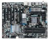
...slot can only accommodate a shorter PCI Express x1 expansion card. For a longer expansion card, use other expansion slots. - 7 - GA-P67A-UD5 Motherboard Layout KB_MS_USB SYS_FAN1 CPU_FAN R_SPDIF ATX_12V_2X USB_1394_ESATA_2 Marvell 88SE9128 USB_1394_ESATA_1 USB30 CPU_LED LGA1155 PW_SW PHASE LED PWR_FAN RST_SW CMOS_SW USB30_LAN AUDIO Realtek RTL8111E F_AUDIO VLI... PCIEX16 PE_LED DDR3_1 DDR3_2 DDR3_3 DDR3_4 DIMM_LED ATX BAT Renesas D720200 PCIEX1_2 PCI1 CODEC SPDIF_O PCIEX8 GA-P67A-UD5 PCI_LED iTE IT8892 Bridge Intel® P67 B_BIOS M_BIOS SA_LED iTE IT8728 T.I.
...slot can only accommodate a shorter PCI Express x1 expansion card. For a longer expansion card, use other expansion slots. - 7 - GA-P67A-UD5 Motherboard Layout KB_MS_USB SYS_FAN1 CPU_FAN R_SPDIF ATX_12V_2X USB_1394_ESATA_2 Marvell 88SE9128 USB_1394_ESATA_1 USB30 CPU_LED LGA1155 PW_SW PHASE LED PWR_FAN RST_SW CMOS_SW USB30_LAN AUDIO Realtek RTL8111E F_AUDIO VLI... PCIEX16 PE_LED DDR3_1 DDR3_2 DDR3_3 DDR3_4 DIMM_LED ATX BAT Renesas D720200 PCIEX1_2 PCI1 CODEC SPDIF_O PCIEX8 GA-P67A-UD5 PCI_LED iTE IT8892 Bridge Intel® P67 B_BIOS M_BIOS SA_LED iTE IT8728 T.I.

Manual
Page 8
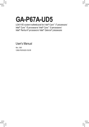
GA-P67A-UD5 Motherboard Block Diagram 2 PCI Express x8 1 PCI Express x16 CPU CLK+/- (133 MHz) PCIe CLK or (100 MHz) LGA1155 CPU DDR3 2133/1866/1600/ 1333/1066 ... PCI Bus DMI Interface LAN 2 SATA 6Gb/s RJ45 Realtek RTL8111E x1 Marvell 88SE9128 x1 PCIe CLK (100 MHz) PCI Express Bus Dual BIOS 2 SATA 6Gb/s Intel® P67 4 SATA 3Gb/s 10 USB 2.0/1.1 (Note) LPC iTE Bus IT8728 PS/2 KB/Mouse TSB43AB23 CODEC 3 IEEE 1394a Surround Speaker Out Center/Subwoofer Speaker Out...
GA-P67A-UD5 Motherboard Block Diagram 2 PCI Express x8 1 PCI Express x16 CPU CLK+/- (133 MHz) PCIe CLK or (100 MHz) LGA1155 CPU DDR3 2133/1866/1600/ 1333/1066 ... PCI Bus DMI Interface LAN 2 SATA 6Gb/s RJ45 Realtek RTL8111E x1 Marvell 88SE9128 x1 PCIe CLK (100 MHz) PCI Express Bus Dual BIOS 2 SATA 6Gb/s Intel® P67 4 SATA 3Gb/s 10 USB 2.0/1.1 (Note) LPC iTE Bus IT8728 PS/2 KB/Mouse TSB43AB23 CODEC 3 IEEE 1394a Surround Speaker Out Center/Subwoofer Speaker Out...

Manual
Page 15
... closely. (Refer to install.) Step 3: Place the cooler atop the CPU, aligning the four push pins through the pin holes on the motherboard. Use extreme care when removing the CPU cooler because the thermal grease/tape between the CPU cooler and CPU may damage the CPU. - ...Push down each push pin. 1-3-2 Installing the CPU Cooler Follow the steps below to correctly install the CPU cooler on the motherboard. (The following procedure uses Intel® boxed cooler as the picture above shows, the installation is to your CPU cooler installation manual for instructions on installing...
... closely. (Refer to install.) Step 3: Place the cooler atop the CPU, aligning the four push pins through the pin holes on the motherboard. Use extreme care when removing the CPU cooler because the thermal grease/tape between the CPU cooler and CPU may damage the CPU. - ...Push down each push pin. 1-3-2 Installing the CPU Cooler Follow the steps below to correctly install the CPU cooler on the motherboard. (The following procedure uses Intel® boxed cooler as the picture above shows, the installation is to your CPU cooler installation manual for instructions on installing...

Manual
Page 29
...audio cable, carefully read the manual for your expansion card. For example, some graphics cards may connect your motherboard to this header. Incorrect connection between the module connector and the motherboard header will make the device unable to activate AC'97 functionality via the audio software in Chapter 5, "... module to certain expansion cards like graphics cards and sound cards. 10) F_AUDIO (Front Panel Audio Header) The front panel audio header supports Intel High Definition audio (HD) and AC'97 audio. For HD Front Panel Audio: For AC'97 Front Panel Audio: Pin No. If...
...audio cable, carefully read the manual for your expansion card. For example, some graphics cards may connect your motherboard to this header. Incorrect connection between the module connector and the motherboard header will make the device unable to activate AC'97 functionality via the audio software in Chapter 5, "... module to certain expansion cards like graphics cards and sound cards. 10) F_AUDIO (Front Panel Audio Header) The front panel audio header supports Intel High Definition audio (HD) and AC'97 audio. For HD Front Panel Audio: For AC'97 Front Panel Audio: Pin No. If...

Manual
Page 79
... load the SATA controller driver first. Or you have to enhance your needs and hardware components. 3. 4-8 eXtreme Hard Drive (X.H.D) With GIGABYTE eXtreme Hard Drive (X.H.D) (Note 1), users can quickly configure a RAIDready system for RAID 0. Before installing the operating system, you can use...utility: Click Cancel to the biggest drive in the Intel Chipset. (Note 2) It is added. Setting Up a RAID-Ready System Step 1: Configure the system BIOS Enter the system BIOS Setup program, set up all motherboard drivers, including the X.H.D utility. Without the driver...
... load the SATA controller driver first. Or you have to enhance your needs and hardware components. 3. 4-8 eXtreme Hard Drive (X.H.D) With GIGABYTE eXtreme Hard Drive (X.H.D) (Note 1), users can quickly configure a RAIDready system for RAID 0. Before installing the operating system, you can use...utility: Click Cancel to the biggest drive in the Intel Chipset. (Note 2) It is added. Setting Up a RAID-Ready System Step 1: Configure the system BIOS Enter the system BIOS Setup program, set up all motherboard drivers, including the X.H.D utility. Without the driver...

Manual
Page 81
... (Note 3) When a RAID set may prepare only one hard drive. • Windows 7/Vista/XP setup disk. • Motherboard driver disk. 5-1-1 Configuring Intel P67 SATA Controllers A. Install SATA hard drive(s) in BIOS Setup. If you use two hard drives with identical model and capacity).... B. Configure a RAID array in your computer Attach one SATA controller on your motherboard, refer to "Chapter 1," "Hardware ...
... (Note 3) When a RAID set may prepare only one hard drive. • Windows 7/Vista/XP setup disk. • Motherboard driver disk. 5-1-1 Configuring Intel P67 SATA Controllers A. Install SATA hard drive(s) in BIOS Setup. If you use two hard drives with identical model and capacity).... B. Configure a RAID array in your computer Attach one SATA controller on your motherboard, refer to "Chapter 1," "Hardware ...

Manual
Page 94
...installing Windows XP, connect a USB floppy disk drive to install Windows 7/Vista/XP onto your floppy disk. A screen will appear. Step 2: For the Intel P67: Insert the floppy disk containing the SATA RAID/AHCI driver and press . For AHCI mode, use with Windows, using a device support disk provided by... use the up arrow key on the keyboard to scroll to your computer. A. Installing Windows XP To install Windows XP, you want from the motherboard driver disk to install a 3rd party SCSI or RAID driver." To install Windows 64-Bit, copy the files in the 64Bit folder. •...
...installing Windows XP, connect a USB floppy disk drive to install Windows 7/Vista/XP onto your floppy disk. A screen will appear. Step 2: For the Intel P67: Insert the floppy disk containing the SATA RAID/AHCI driver and press . For AHCI mode, use with Windows, using a device support disk provided by... use the up arrow key on the keyboard to scroll to your computer. A. Installing Windows XP To install Windows XP, you want from the motherboard driver disk to install a 3rd party SCSI or RAID driver." To install Windows 64-Bit, copy the files in the 64Bit folder. •...

Manual
Page 97
The Status item on the left of the screen displays the rebuild progress. Step 1: Go to the Manage menu and click Rebuild to rebuild the RAID and click Rebuild. • Performing the Rebuild in the Operating System While in Manage Volume. Step 2: Select a new drive to another disk in the operating system, make sure the chipset driver has been installed from All Programs in the Start menu. Appendix Then launch the Intel Rapid Storage Technology utility from the motherboard driver disk. Step 3: After the RAID 1 volume rebuilding, the Status will display as Normal. - 97 -
The Status item on the left of the screen displays the rebuild progress. Step 1: Go to the Manage menu and click Rebuild to rebuild the RAID and click Rebuild. • Performing the Rebuild in the Operating System While in Manage Volume. Step 2: Select a new drive to another disk in the operating system, make sure the chipset driver has been installed from All Programs in the Start menu. Appendix Then launch the Intel Rapid Storage Technology utility from the motherboard driver disk. Step 3: After the RAID 1 volume rebuilding, the Status will display as Normal. - 97 -


