Manual
Page 1
GA-P67A-UD3 GA-PH67A-UD3 GA-PH67-UD3 LGA1155 socket motherboard for Intel® Core™ i7 processors/ Intel® Core™ i5 processors/Intel® Core™ i3 processors/ Intel® Pentium® processors/Intel® Celeron® processors User's Manual Rev. 1002 12ME-P67AUD3-1002R
GA-P67A-UD3 GA-PH67A-UD3 GA-PH67-UD3 LGA1155 socket motherboard for Intel® Core™ i7 processors/ Intel® Core™ i5 processors/Intel® Core™ i3 processors/ Intel® Pentium® processors/Intel® Celeron® processors User's Manual Rev. 1002 12ME-P67AUD3-1002R
Manual
Page 2
Motherboard GA-P67A-UD3/GA-PH67A-UD3/GA-PH67-UD3 Oct. 26, 2010 Motherboard GA-P67A-UD3/ GA-PH67A-UD3/ GA-PH67-UD3 Oct. 26, 2010
Motherboard GA-P67A-UD3/GA-PH67A-UD3/GA-PH67-UD3 Oct. 26, 2010 Motherboard GA-P67A-UD3/ GA-PH67A-UD3/ GA-PH67-UD3 Oct. 26, 2010
Manual
Page 3
..., copied, translated, transmitted, or published in the use of GIGABYTE. Documentation Classifications In order to assist in any form or by GIGABYTE without GIGABYTE's prior written permission. Check your motherboard looks like this manual may be made by any means without ...prior notice. For product-related information, check on our website at: http://www.gigabyte.com Identifying Your Motherboard Revision The revision number on your motherboard revision before updating motherboard BIOS, drivers, or when looking for technical information. Example: Copyright © 2010 GIGA...
..., copied, translated, transmitted, or published in the use of GIGABYTE. Documentation Classifications In order to assist in any form or by GIGABYTE without GIGABYTE's prior written permission. Check your motherboard looks like this manual may be made by any means without ...prior notice. For product-related information, check on our website at: http://www.gigabyte.com Identifying Your Motherboard Revision The revision number on your motherboard revision before updating motherboard BIOS, drivers, or when looking for technical information. Example: Copyright © 2010 GIGA...
Manual
Page 4
Table of Contents Box Contents...6 Optional Items...6 GA-P67A-UD3/GA-PH67A-UD3/GA-PH67-UD3 Motherboard Layout 7 GA-P67A-UD3/GA-PH67A-UD3/GA-PH67-UD3 Motherboard Block Diagram 8 Chapter 1 Hardware Installation 9 1-1 Installation Precautions 9 1-2 Product Specifications 10 1-3 Installing the CPU and CPU Cooler 13 1-3-1 Installing the CPU 13 1-3-2 Installing the CPU Cooler ...
Table of Contents Box Contents...6 Optional Items...6 GA-P67A-UD3/GA-PH67A-UD3/GA-PH67-UD3 Motherboard Layout 7 GA-P67A-UD3/GA-PH67A-UD3/GA-PH67-UD3 Motherboard Block Diagram 8 Chapter 1 Hardware Installation 9 1-1 Installation Precautions 9 1-2 Product Specifications 10 1-3 Installing the CPU and CPU Cooler 13 1-3-1 Installing the CPU 13 1-3-2 Installing the CPU Cooler ...
Manual
Page 6
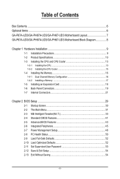
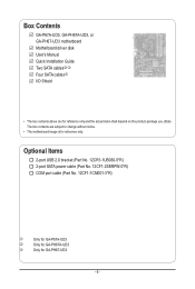
Box Contents GA-P67A-UD3, GA-PH67A-UD3, or GA-PH67-UD3 motherboard Motherboard driver disk User's Manual Quick Installation Guide Two SATA cableskl Four SATA cablesj I/O Shield • The box contents above are subject to change without notice. • The motherboard image is for reference only. Optional Items 2-port USB 2.0 bracket (Part No. 12CR1-1UB030-5*R) 2-port SATA power cable (Part...
Box Contents GA-P67A-UD3, GA-PH67A-UD3, or GA-PH67-UD3 motherboard Motherboard driver disk User's Manual Quick Installation Guide Two SATA cableskl Four SATA cablesj I/O Shield • The box contents above are subject to change without notice. • The motherboard image is for reference only. Optional Items 2-port USB 2.0 bracket (Part No. 12CR1-1UB030-5*R) 2-port SATA power cable (Part...
Manual
Page 7
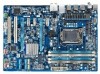
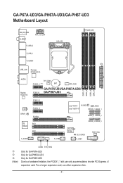
For a longer expansion card, use other expansion slots. - 7 - GA-P67A-UD3/GA-PH67A-UD3/GA-PH67-UD3 Motherboard Layout KB_MS_USB R_SPDIF ATX_12V_2X4 R_USB_2 LGA1155 PHASE LED R_USB_1 R_USB30 ATX USB_LAN Renesas D720200jk AUDIO Realtek RTL8111E CODEC SPDIF_O iTE IT8728 F_AUDIO SYS_FAN1 PCIEX1_1 (Note) BAT CPU_FAN GA-P67A-UD3/GA-PH67A-UD3/ PCIEX16 GA-PH67-UD3 DDR3_1 DDR3_2 DDR3_3 DDR3_4 PCIEX1_2 PCIEX1_3 PCIEX4 PCI1 PCI2 F_USB2 Intel...
For a longer expansion card, use other expansion slots. - 7 - GA-P67A-UD3/GA-PH67A-UD3/GA-PH67-UD3 Motherboard Layout KB_MS_USB R_SPDIF ATX_12V_2X4 R_USB_2 LGA1155 PHASE LED R_USB_1 R_USB30 ATX USB_LAN Renesas D720200jk AUDIO Realtek RTL8111E CODEC SPDIF_O iTE IT8728 F_AUDIO SYS_FAN1 PCIEX1_1 (Note) BAT CPU_FAN GA-P67A-UD3/GA-PH67A-UD3/ PCIEX16 GA-PH67-UD3 DDR3_1 DDR3_2 DDR3_3 DDR3_4 PCIEX1_2 PCIEX1_3 PCIEX4 PCI1 PCI2 F_USB2 Intel...
Manual
Page 8
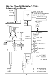
GA-P67A-UD3/GA-PH67A-UD3/GA-PH67-UD3 Motherboard Block Diagram PCIe CLK (100 MHz) 1 PCI Express x16 LGA1155 CPU CPU CLK+/- (100 MHz) DDR3 2133/1866/1600/1333/1066 MHzj DDR3 1333/1066/.../Mouse Surround Speaker Out Center/Subwoofer Speaker Out Side Speaker Out MIC Line Out Line In S/PDIF Out 2 PCI PCI CLK (33 MHz) j k l Only for GA-P67A-UD3 Only for GA-PH67A-UD3 Only for GA-PH67-UD3 - 8 -
GA-P67A-UD3/GA-PH67A-UD3/GA-PH67-UD3 Motherboard Block Diagram PCIe CLK (100 MHz) 1 PCI Express x16 LGA1155 CPU CPU CLK+/- (100 MHz) DDR3 2133/1866/1600/1333/1066 MHzj DDR3 1333/1066/.../Mouse Surround Speaker Out Center/Subwoofer Speaker Out Side Speaker Out MIC Line Out Line In S/PDIF Out 2 PCI PCI CLK (33 MHz) j k l Only for GA-P67A-UD3 Only for GA-PH67A-UD3 Only for GA-PH67-UD3 - 8 -

Manual
Page 9
... an electrostatic shielding container. • Before unplugging the power supply cable from the power outlet before installing or removing the motherboard or other hardware components. • When connecting hardware components to the internal connectors on the computer power during the installation .... - 9 - These stickers are required for warranty validation. • Always remove the AC power by your dealer. ponents such as a motherboard, CPU or memory. Hardware Installation If you are uncertain about any metal leads or connectors. • It is best to wear an electrostatic ...
... an electrostatic shielding container. • Before unplugging the power supply cable from the power outlet before installing or removing the motherboard or other hardware components. • When connecting hardware components to the internal connectors on the computer power during the installation .... - 9 - These stickers are required for warranty validation. • Always remove the AC power by your dealer. ponents such as a motherboard, CPU or memory. Hardware Installation If you are uncertain about any metal leads or connectors. • It is best to wear an electrostatic ...

Manual
Page 12
... Charge Support for Cloud OC Support for Q-Share Norton Internet Security (OEM version) Operating System w Support for EasyTune * Available functions in EasyTune may differ by motherboard model. BIOS w w w w Unique Features w w w w w w w w w w w w w w Bundled Software w 2 x 32 Mbit flash Use of licensed ...XP Form Factor w ATX Form Factor; 30.5cm x 21.5cm * GIGABYTE reserves the right to make any changes to the product specifications and product-related information without prior notice.
... Charge Support for Cloud OC Support for Q-Share Norton Internet Security (OEM version) Operating System w Support for EasyTune * Available functions in EasyTune may differ by motherboard model. BIOS w w w w Unique Features w w w w w w w w w w w w w w Bundled Software w 2 x 32 Mbit flash Use of licensed ...XP Form Factor w ATX Form Factor; 30.5cm x 21.5cm * GIGABYTE reserves the right to make any changes to the product specifications and product-related information without prior notice.

Manual
Page 13
If you may occur. • Set the CPU host frequency in accordance with the CPU specifications. Locate the alignment keys on the motherboard CPU socket and the notches on the CPU - 13 - LGA1155 CPU Socket Alignment Key Alignment Key Pin One Corner of the CPU. • Do not ... meet the standard requirements for the latest CPU support list.) • Always turn on the computer if the CPU cooler is not recommended that the motherboard supports the CPU. (Go to GIGABYTE's website for the peripherals. It is not installed, otherwise overheating and dam- Hardware Installation
If you may occur. • Set the CPU host frequency in accordance with the CPU specifications. Locate the alignment keys on the motherboard CPU socket and the notches on the CPU - 13 - LGA1155 CPU Socket Alignment Key Alignment Key Pin One Corner of the CPU. • Do not ... meet the standard requirements for the latest CPU support list.) • Always turn on the computer if the CPU cooler is not recommended that the motherboard supports the CPU. (Go to GIGABYTE's website for the peripherals. It is not installed, otherwise overheating and dam- Hardware Installation

Manual
Page 14
... lifted as shown. When replacing the load plate, make sure to lightly replace the load plate. Step 5: Push the CPU socket lever back into the motherboard CPU socket. B. Before installing the CPU, make sure the front end of the load plate is properly inserted, use one corner of the socket cover...
... lifted as shown. When replacing the load plate, make sure to lightly replace the load plate. Step 5: Push the CPU socket lever back into the motherboard CPU socket. B. Before installing the CPU, make sure the front end of the load plate is properly inserted, use one corner of the socket cover...

Manual
Page 15
... thermal grease on the push pins diagonally. 1-3-2 Installing the CPU Cooler Follow the steps below to correctly install the CPU cooler on the motherboard. (The following procedure uses Intel® boxed cooler as the picture above shows, the installation is to install.) Step 3: Place the... aligning the four push pins through the pin holes on installing the cooler.) Step 5: After the installation, check the back of the motherboard. Push down each push pin. Step 6: Finally, attach the power connector of the installed CPU. Inadequately removing the CPU cooler may adhere...
... thermal grease on the push pins diagonally. 1-3-2 Installing the CPU Cooler Follow the steps below to correctly install the CPU cooler on the motherboard. (The following procedure uses Intel® boxed cooler as the picture above shows, the installation is to install.) Step 3: Place the... aligning the four push pins through the pin holes on installing the cooler.) Step 5: After the installation, check the back of the motherboard. Push down each push pin. Step 6: Finally, attach the power connector of the installed CPU. Inadequately removing the CPU cooler may adhere...

Manual
Page 16
... the power cord from the power outlet before installing the memory in only one DDR3 memory module is recommended that the motherboard supports the memory. 1-4 Installing the Memory 1-4-1 Read the following guidelines before you are divided into two channels and each... foolproof design. A memory module can be used . (Go to GIGABYTE's website for optimum performance. When enabling Dual Channel mode with two or four memory modules, it is installed. 2. Dual Channel Memory Configuration This motherboard provides four DDR3 memory sockets and supports Dual Channel Technology. DS/SS...
... the power cord from the power outlet before installing the memory in only one DDR3 memory module is recommended that the motherboard supports the memory. 1-4 Installing the Memory 1-4-1 Read the following guidelines before you are divided into two channels and each... foolproof design. A memory module can be used . (Go to GIGABYTE's website for optimum performance. When enabling Dual Channel mode with two or four memory modules, it is installed. 2. Dual Channel Memory Configuration This motherboard provides four DDR3 memory sockets and supports Dual Channel Technology. DS/SS...

Manual
Page 17
... your memory modules in one direction. Step 1: Note the orientation of the socket will snap into the memory socket. Place the memory module on this motherboard. DDR3 and DDR2 DIMMs are not compatible to each other or DDR DIMMs. Be sure to the memory module. Step 2: The clips at both ends...
... your memory modules in one direction. Step 1: Note the orientation of the socket will snap into the memory socket. Place the memory module on this motherboard. DDR3 and DDR2 DIMMs are not compatible to each other or DDR DIMMs. Be sure to the memory module. Step 2: The clips at both ends...
Manual
Page 18
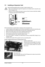
.... • Removing the Card: Press the white latch at the end of the PCI Express slot to install an expansion card: • Make sure the motherboard supports the expansion card. Example: Installing and Removing a PCI Express Graphics Card: • Installing a Graphics Card: Gently push down on the top edge of the...
.... • Removing the Card: Press the white latch at the end of the PCI Express slot to install an expansion card: • Make sure the motherboard supports the expansion card. Example: Installing and Removing a PCI Express Graphics Card: • Installing a Graphics Card: Gently push down on the top edge of the...
Manual
Page 19
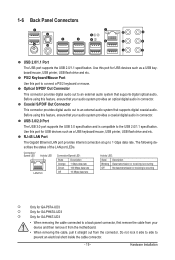
... and is occurring j k l Only for GA-P67A-UD3 Only for GA-PH67A-UD3 Only for GA-PH67-UD3 • When removing the cable connected to prevent an electrical short inside the cable connector. - 19 - PS/2 Keyboard/Mouse Port Use this feature, ensure that your device and then remove it from the motherboard. • When removing the cable, pull...
... and is occurring j k l Only for GA-P67A-UD3 Only for GA-PH67A-UD3 Only for GA-PH67-UD3 • When removing the cable connected to prevent an electrical short inside the cable connector. - 19 - PS/2 Keyboard/Mouse Port Use this feature, ensure that your device and then remove it from the motherboard. • When removing the cable, pull...

Manual
Page 21
.../1 8) SATA2_2/3/4/5 5 12 14 9 9) F_PANEL 10) F_AUDIO 11) SPDIF_O 12) F_USB1/F_USB2 13) COMA 14) CLR_CMOS 15) PHASE_LED Read the following guidelines before turning on the motherboard. - 21 - Hardware Installation Unplug the power cord from the power outlet to prevent damage to the devices. • After installing the device and before connecting...
.../1 8) SATA2_2/3/4/5 5 12 14 9 9) F_PANEL 10) F_AUDIO 11) SPDIF_O 12) F_USB1/F_USB2 13) COMA 14) CLR_CMOS 15) PHASE_LED Read the following guidelines before turning on the motherboard. - 21 - Hardware Installation Unplug the power cord from the power outlet to prevent damage to the devices. • After installing the device and before connecting...

Manual
Page 22
... be used (500W or greater). The power connector possesses a foolproof design. If the 12V power connector is turned off and all the components on the motherboard. If a power supply is recommended that a power supply that does not provide the required power, the result can lead to an unstable or unbootable system...
... be used (500W or greater). The power connector possesses a foolproof design. If the 12V power connector is turned off and all the components on the motherboard. If a power supply is recommended that a power supply that does not provide the required power, the result can lead to an unstable or unbootable system...

Manual
Page 23
... battery holder and wait for 5 seconds.) 3. Plug in the power cord and restart your computer. • Always turn off . The motherboard supports CPU fan speed control, which requires the use of a CPU fan with an equivalent one minute. (Or use a metal object like...about the bat- Definition 1 GND 1 2 +12V / Speed Control CPU_FAN 3 Sense 4 Speed Control SYS_FAN2: Pin No. 3/4/5) CPU_FAN/SYS_FAN1/SYS_FAN2/PWR_FAN (Fan Headers) The motherboard has a 4-pin CPU fan header (CPU_FAN), a 4-pin (SYS_FAN2) and a 3-pin (SYS_ FAN1) system fan headers, and a 3-pin power fan header (PWR_FAN). ...
... battery holder and wait for 5 seconds.) 3. Plug in the power cord and restart your computer. • Always turn off . The motherboard supports CPU fan speed control, which requires the use of a CPU fan with an equivalent one minute. (Or use a metal object like...about the bat- Definition 1 GND 1 2 +12V / Speed Control CPU_FAN 3 Sense 4 Speed Control SYS_FAN2: Pin No. 3/4/5) CPU_FAN/SYS_FAN1/SYS_FAN2/PWR_FAN (Fan Headers) The motherboard has a 4-pin CPU fan header (CPU_FAN), a 4-pin (SYS_FAN2) and a 3-pin (SYS_ FAN1) system fan headers, and a 3-pin power fan header (PWR_FAN). ...

Manual
Page 26
... assignments of the module connector match the pin assignments of a single plug. Incorrect connection between the module connector and the motherboard header will make the device unable to activate AC'97 functionality via the audio software in Chapter 5, "Configuring 2/4/5.1/7.1-Channel Audio...." • Audio signals will be present on each wire instead of the motherboard header. You may require you wish to connect an HDMI display to Chapter 5, "Configuring 2/4/5.1/7.1-Channel Audio." • Some chassis provide...
... assignments of the module connector match the pin assignments of a single plug. Incorrect connection between the module connector and the motherboard header will make the device unable to activate AC'97 functionality via the audio software in Chapter 5, "Configuring 2/4/5.1/7.1-Channel Audio...." • Audio signals will be present on each wire instead of the motherboard header. You may require you wish to connect an HDMI display to Chapter 5, "Configuring 2/4/5.1/7.1-Channel Audio." • Some chassis provide...


