Manual
Page 2
Motherboard GA-P61-S3-B3 Jun. 03, 2011 Motherboard GA-P61-S3-B3 Jun. 03, 2011
Motherboard GA-P61-S3-B3 Jun. 03, 2011 Motherboard GA-P61-S3-B3 Jun. 03, 2011
Manual
Page 3
... manual is protected by any form or by copyright laws and is 1.0. Check your motherboard looks like this manual are legally registered to their respective owners. Example: Disclaimer Information in this manual may be made by GIGABYTE without GIGABYTE's prior written permission. In order to the specifications and features in any means...
... manual is protected by any form or by copyright laws and is 1.0. Check your motherboard looks like this manual are legally registered to their respective owners. Example: Disclaimer Information in this manual may be made by GIGABYTE without GIGABYTE's prior written permission. In order to the specifications and features in any means...
Manual
Page 4
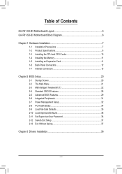
Table of Contents GA-P61-S3-B3 Motherboard Layout 5 GA-P61-S3-B3 Motherboard Block Diagram 6 Chapter 1 Hardware Installation 7 1-1 Installation Precautions 7 1-2 Product Specifications 8 1-3 Installing the CPU and CPU Cooler 10 1-4 Installing the Memory 11 1-5 Installing an Expansion Card 11 1-6 ...
Table of Contents GA-P61-S3-B3 Motherboard Layout 5 GA-P61-S3-B3 Motherboard Block Diagram 6 Chapter 1 Hardware Installation 7 1-1 Installation Precautions 7 1-2 Product Specifications 8 1-3 Installing the CPU and CPU Cooler 10 1-4 Installing the Memory 11 1-5 Installing an Expansion Card 11 1-6 ...
Manual
Page 5
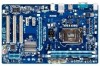
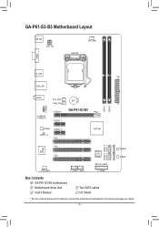
...® H61 SATA2_2 SATA2_3 SATA2_0 SATA2_1 iTE IT8728 PCI2 M_BIOS PCIe to PCI PCI3 Bridge B_BIOS CLR_CMOS SYS_FAN2 F_USB2 F_USB1 F_PANEL Box Contents GA-P61-S3-B3 motherboard Motherboard driver disk User's Manual Two SATA cables I/O Shield * The box contents above are for reference only and the actual items shall depend on the product ...
...® H61 SATA2_2 SATA2_3 SATA2_0 SATA2_1 iTE IT8728 PCI2 M_BIOS PCIe to PCI PCI3 Bridge B_BIOS CLR_CMOS SYS_FAN2 F_USB2 F_USB1 F_PANEL Box Contents GA-P61-S3-B3 motherboard Motherboard driver disk User's Manual Two SATA cables I/O Shield * The box contents above are for reference only and the actual items shall depend on the product ...
Manual
Page 6
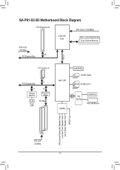
GA-P61-S3-B3 Motherboard Block Diagram 1 PCI Express x16 CPU CLK+/- (100 MHz) LGA1155 CPU DDR3 1333/1066/800 MHz Dual Channel Memory PCIe CLK (100 MHz) x16 PCI Express Bus DMI 2.0 2 PCI Express x1 PCI Express Bus x1 Atheros AR8151 x1 x1 PCIe to PCI Bridge RJ45 PCI Bus LAN Intel® H61 Dual BIOS 4 SATA 3Gb/s 8 USB 2.0/1.1 LPC Bus iTE IT8728 CODEC COM Port PS/2 KB/Mouse MIC (Center/Subwoofer Speaker Out) Line Out (Front Speaker Out) Line In (Rear Speaker Out) S/PDIF Out 3 PCI PCI CLK (33 MHz) - 6 -
GA-P61-S3-B3 Motherboard Block Diagram 1 PCI Express x16 CPU CLK+/- (100 MHz) LGA1155 CPU DDR3 1333/1066/800 MHz Dual Channel Memory PCIe CLK (100 MHz) x16 PCI Express Bus DMI 2.0 2 PCI Express x1 PCI Express Bus x1 Atheros AR8151 x1 x1 PCIe to PCI Bridge RJ45 PCI Bus LAN Intel® H61 Dual BIOS 4 SATA 3Gb/s 8 USB 2.0/1.1 LPC Bus iTE IT8728 CODEC COM Port PS/2 KB/Mouse MIC (Center/Subwoofer Speaker Out) Line Out (Front Speaker Out) Line In (Rear Speaker Out) S/PDIF Out 3 PCI PCI CLK (33 MHz) - 6 -
Manual
Page 7
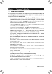
... on an uneven surface. •• Do not place the computer system in a high-temperature environment. •• Turning on the motherboard, make sure they are required for warranty validation. •• Always remove the AC power by your hands dry and first touch a... leads or connectors. •• It is best to the internal connectors on the computer power during the installation process can become damaged as a motherboard, CPU or memory. ponents such as a result of the product, please consult a certified computer technician. - 7 - Prior to installation, carefully ...
... on an uneven surface. •• Do not place the computer system in a high-temperature environment. •• Turning on the motherboard, make sure they are required for warranty validation. •• Always remove the AC power by your hands dry and first touch a... leads or connectors. •• It is best to the internal connectors on the computer power during the installation process can become damaged as a motherboard, CPU or memory. ponents such as a result of the product, please consult a certified computer technician. - 7 - Prior to installation, carefully ...
Manual
Page 9
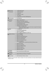
... Center ŠŠ Support for Xpress Install ŠŠ Support for Xpress Recovery2 ŠŠ Support for EasyTune * Available functions in EasyTune may differ by motherboard model. ŠŠ Support for Smart 6™ ŠŠ Support for Auto Green ŠŠ Support for ON/OFF Charge ŠŠ Support for Cloud...
... Center ŠŠ Support for Xpress Install ŠŠ Support for Xpress Recovery2 ŠŠ Support for EasyTune * Available functions in EasyTune may differ by motherboard model. ŠŠ Support for Smart 6™ ŠŠ Support for Auto Green ŠŠ Support for ON/OFF Charge ŠŠ Support for Cloud...
Manual
Page 10
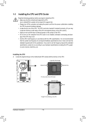
... Locate the pin one of the CPU Socket LGA1155 CPU Notch Notch Triangle Pin One Marking on the CPU. Locate the alignment keys on the motherboard CPU socket and the notches on the CPU Hardware Installation - 10 - If you may locate the notches on both sides of the CPU and...•• Apply an even and thin layer of thermal grease on the computer if the CPU cooler is not recommended that the motherboard supports the CPU. (Go to GIGABYTE's website for the peripherals. Installing the CPU A. The CPU cannot be set the frequency beyond hardware specifications since it does not meet...
... Locate the pin one of the CPU Socket LGA1155 CPU Notch Notch Triangle Pin One Marking on the CPU. Locate the alignment keys on the motherboard CPU socket and the notches on the CPU Hardware Installation - 10 - If you may locate the notches on both sides of the CPU and...•• Apply an even and thin layer of thermal grease on the computer if the CPU cooler is not recommended that the motherboard supports the CPU. (Go to GIGABYTE's website for the peripherals. Installing the CPU A. The CPU cannot be set the frequency beyond hardware specifications since it does not meet...
Manual
Page 11
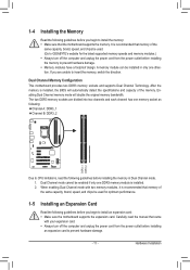
... unplug the power cord from the power outlet before you begin to install an expansion card: •• Make sure the motherboard supports the expansion card. Enabling Dual Channel memory mode will automatically detect the specifications and capacity of the same capacity, brand, speed...install the memory: •• Make sure that memory of the same capacity, brand, speed, and chips be used . (Go to GIGABYTE's website for optimum performance. 1-5 Installing an Expansion Card Read the following guidelines before installing the memory to prevent hardware damage. ••...
... unplug the power cord from the power outlet before you begin to install an expansion card: •• Make sure the motherboard supports the expansion card. Enabling Dual Channel memory mode will automatically detect the specifications and capacity of the same capacity, brand, speed...install the memory: •• Make sure that memory of the same capacity, brand, speed, and chips be used . (Go to GIGABYTE's website for optimum performance. 1-5 Installing an Expansion Card Read the following guidelines before installing the memory to prevent hardware damage. ••...
Manual
Page 12
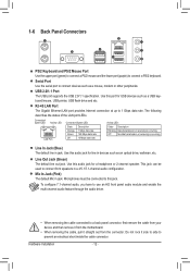
... Ethernet LAN port provides Internet connection at up to a back panel connector, first remove the cable from your device and then remove it from the motherboard. •• When removing the cable, pull it side to side to connect a PS/2 keyboard. Use this jack. To configure 7.1-channel audio, you have to...
... Ethernet LAN port provides Internet connection at up to a back panel connector, first remove the cable from your device and then remove it from the motherboard. •• When removing the cable, pull it side to side to connect a PS/2 keyboard. Use this jack. To configure 7.1-channel audio, you have to...

Manual
Page 13
... and your devices are compliant with the connectors you wish to connect. •• Before installing the devices, be sure to the connector on the motherboard. - 13 - 1-7 Internal Connectors 1 3 12 4 5 8 10 4 1) ATX_12V 2) ATX 3) CPU_FAN 4) SYS_FAN1/2 5) PWR_FAN 6) SATA2_0/1/2/3 2 6 9 11 7 7) F_PANEL 8) F_AUDIO 9) F_USB1/2 10) SPDIF_O 11) CLR_CMOS 12) BAT Read the following guidelines...
... and your devices are compliant with the connectors you wish to connect. •• Before installing the devices, be sure to the connector on the motherboard. - 13 - 1-7 Internal Connectors 1 3 12 4 5 8 10 4 1) ATX_12V 2) ATX 3) CPU_FAN 4) SYS_FAN1/2 5) PWR_FAN 6) SATA2_0/1/2/3 2 6 9 11 7 7) F_PANEL 8) F_AUDIO 9) F_USB1/2 10) SPDIF_O 11) CLR_CMOS 12) BAT Read the following guidelines...

Manual
Page 14
... that can withstand high power consumption be used (500W or greater). If the 12V power connector is turned off and all the components on the motherboard. If a power supply is recommended that a power supply that does not provide the required power, the result can lead to all devices are properly installed...
... that can withstand high power consumption be used (500W or greater). If the 12V power connector is turned off and all the components on the motherboard. If a power supply is recommended that a power supply that does not provide the required power, the result can lead to all devices are properly installed...
Manual
Page 15
... a system fan be sure to prevent your SATA hard drive. Most fan headers possess a foolproof insertion design. 3/4/5) CPU_FAN/SYS_FAN1/SYS_FAN2/PWR_FAN (Fan Headers) The motherboard has a 4-pin CPU fan header (CPU_FAN), a 4-pin (SYS_FAN2) and a 3-pin (SYS_ FAN1) system fan headers, and a 3-pin power fan header... 3 Sense •• Be sure to connect fan cables to the fan headers to connect it is the ground wire). The motherboard supports CPU fan speed control, which requires the use of the SATA cable to SATA 3Gb/s standard and are not configuration jumper blocks...
... a system fan be sure to prevent your SATA hard drive. Most fan headers possess a foolproof insertion design. 3/4/5) CPU_FAN/SYS_FAN1/SYS_FAN2/PWR_FAN (Fan Headers) The motherboard has a 4-pin CPU fan header (CPU_FAN), a 4-pin (SYS_FAN2) and a 3-pin (SYS_ FAN1) system fan headers, and a 3-pin power fan header... 3 Sense •• Be sure to connect fan cables to the fan headers to connect it is the ground wire). The motherboard supports CPU fan speed control, which requires the use of the SATA cable to SATA 3Gb/s standard and are not configuration jumper blocks...
Manual
Page 17
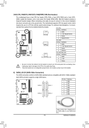
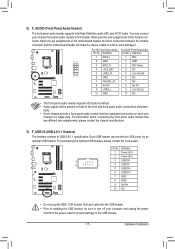
Incorrect connection between the module connector and the motherboard header will be sure to turn off your chassis front panel audio module to this header. Hardware Installation 8) F_AUDIO (Front Panel Audio Header) The front ...) The headers conform to the USB bracket. - 17 - For information about connecting the front panel audio module that has separated connectors on both of the motherboard header. For purchasing the optional USB bracket, please contact the local dealer. Definition 1 Power (5V) 2 Power (5V) 9 1 3 USB DX- 10 2 4 USB DY- 5 USB DX+ 6 USB...
Incorrect connection between the module connector and the motherboard header will be sure to turn off your chassis front panel audio module to this header. Hardware Installation 8) F_AUDIO (Front Panel Audio Header) The front ...) The headers conform to the USB bracket. - 17 - For information about connecting the front panel audio module that has separated connectors on both of the motherboard header. For purchasing the optional USB bracket, please contact the local dealer. Definition 1 Power (5V) 2 Power (5V) 9 1 3 USB DX- 10 2 4 USB DY- 5 USB DX+ 6 USB...
Manual
Page 18
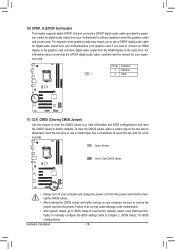
...Header) This header supports digital S/PDIF Out and connects a S/PDIF digital audio cable (provided by expansion cards) for digital audio output from your motherboard to certain expansion cards like a screwdriver to touch the two pins for a few seconds. date information and BIOS configurations) and reset the CMOS values... your expansion card. Failure to do so may require you to the graphics card and have digital audio output from your motherboard to your computer, be sure to Chapter 2, "BIOS Setup," for BIOS configurations). For example, some graphics cards may cause damage to the...
...Header) This header supports digital S/PDIF Out and connects a S/PDIF digital audio cable (provided by expansion cards) for digital audio output from your motherboard to certain expansion cards like a screwdriver to touch the two pins for a few seconds. date information and BIOS configurations) and reset the CMOS values... your expansion card. Failure to do so may require you to the graphics card and have digital audio output from your motherboard to your computer, be sure to Chapter 2, "BIOS Setup," for BIOS configurations). For example, some graphics cards may cause damage to the...
Manual
Page 20
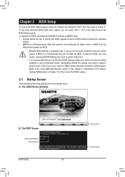
... turned on. P61-S3-B3 E7 . . . . : BIOS Setup : XpressRecovery2 : Boot Menu : Qflash 05/25/2011-H61-7A89WG0OC-00 Function Keys Function Keys BIOS Setup - 20 - A. To upgrade the BIOS, use either the GIGABYTE Q-Flash or @BIOS utility. •• Q-Flash allows the user to boot. The LOGO Screen (Default): B. The POST Screen Motherboard Model BIOS...
... turned on. P61-S3-B3 E7 . . . . : BIOS Setup : XpressRecovery2 : Boot Menu : Qflash 05/25/2011-H61-7A89WG0OC-00 Function Keys Function Keys BIOS Setup - 20 - A. To upgrade the BIOS, use either the GIGABYTE Q-Flash or @BIOS utility. •• Q-Flash allows the user to boot. The LOGO Screen (Default): B. The POST Screen Motherboard Model BIOS...
Manual
Page 32
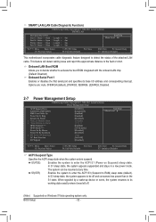
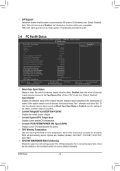
...:ss) Alarm HPET Support (Note) HPET Mode (Note) Power On By Mouse Power On By Keyboard x KB Power ON Password AC Back Function ErP Support [S3(STR)] [Instant-Off] [Enabled] [Enabled] [Disabled] Everyday 0 : 0 : 0 [Enabled] [32-bit mode] [Disabled] [Disabled] Enter [Soft-Off] [...: Previous Values +/-/PU/PD: Value F10: Save F6: Fail-Safe Defaults ESC: Exit F1: General Help F7: Optimized Defaults This motherboard incorporates cable diagnostic feature designed to activate the boot ROM integrated with the onboard LAN chip. (Default: Disabled) Onboard Serial Port 1...
...:ss) Alarm HPET Support (Note) HPET Mode (Note) Power On By Mouse Power On By Keyboard x KB Power ON Password AC Back Function ErP Support [S3(STR)] [Instant-Off] [Enabled] [Enabled] [Disabled] Everyday 0 : 0 : 0 [Enabled] [32-bit mode] [Disabled] [Disabled] Enter [Soft-Off] [...: Previous Values +/-/PU/PD: Value F10: Save F6: Fail-Safe Defaults ESC: Exit F1: General Help F7: Optimized Defaults This motherboard incorporates cable diagnostic feature designed to activate the boot ROM integrated with the onboard LAN chip. (Default: Disabled) Onboard Serial Port 1...
Manual
Page 34
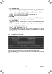
... threshold, BIOS will show "No" at next boot. (Default: Disabled) Case Opened Displays the detection status of the chassis intrusion detection device attached to the motherboard CI header. Enabled clears the record of previous chassis intrusion status. If the system chassis cover is removed, this occurs. (Default: Disabled) BIOS Setup - 34...
... threshold, BIOS will show "No" at next boot. (Default: Disabled) Case Opened Displays the detection status of the chassis intrusion detection device attached to the motherboard CI header. Enabled clears the record of previous chassis intrusion status. If the system chassis cover is removed, this occurs. (Default: Disabled) BIOS Setup - 34...
Manual
Page 35
... fan to Manual. Slope PWM Allows you to load the safest BIOS default settings. Options are the safest and most stable BIOS settings for the motherboard. - 35 - This item is configurable only when CPU Smart FAN Control is set for a 3-pin CPU fan. PWM Sets PWM mode for a 4-pin CPU fan...
... fan to Manual. Slope PWM Allows you to load the safest BIOS default settings. Options are the safest and most stable BIOS settings for the motherboard. - 35 - This item is configurable only when CPU Smart FAN Control is set for a 3-pin CPU fan. PWM Sets PWM mode for a 4-pin CPU fan...
Manual
Page 38
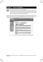
... to install. Chapter 3 Drivers Installation •• Before installing the drivers, first install the operating system. •• After installing the operating system, insert the motherboard driver disk into your system and then list all the recommended drivers. You can click the Install All button and "Xpress Install" will automatically scan...
... to install. Chapter 3 Drivers Installation •• Before installing the drivers, first install the operating system. •• After installing the operating system, insert the motherboard driver disk into your system and then list all the recommended drivers. You can click the Install All button and "Xpress Install" will automatically scan...


