Manual
Page 6
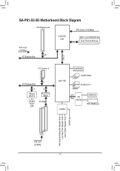
GA-P61-S3-B3 Motherboard Block Diagram 1 PCI Express x16 CPU CLK+/- (100 MHz) LGA1155 CPU DDR3 1333/1066/800 MHz Dual Channel Memory PCIe CLK (100 MHz) x16 PCI Express Bus DMI 2.0 2 PCI Express x1 PCI Express Bus x1 Atheros AR8151 x1 x1 PCIe to PCI Bridge RJ45 PCI Bus LAN Intel® H61 Dual BIOS 4 SATA 3Gb/s 8 USB 2.0/1.1 LPC Bus iTE IT8728 CODEC COM Port PS/2 KB/Mouse MIC (Center/Subwoofer Speaker Out) Line Out (Front Speaker Out) Line In (Rear Speaker Out) S/PDIF Out 3 PCI PCI CLK (33 MHz) - 6 -
GA-P61-S3-B3 Motherboard Block Diagram 1 PCI Express x16 CPU CLK+/- (100 MHz) LGA1155 CPU DDR3 1333/1066/800 MHz Dual Channel Memory PCIe CLK (100 MHz) x16 PCI Express Bus DMI 2.0 2 PCI Express x1 PCI Express Bus x1 Atheros AR8151 x1 x1 PCIe to PCI Bridge RJ45 PCI Bus LAN Intel® H61 Dual BIOS 4 SATA 3Gb/s 8 USB 2.0/1.1 LPC Bus iTE IT8728 CODEC COM Port PS/2 KB/Mouse MIC (Center/Subwoofer Speaker Out) Line Out (Front Speaker Out) Line In (Rear Speaker Out) S/PDIF Out 3 PCI PCI CLK (33 MHz) - 6 -
Manual
Page 12
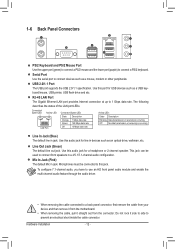
...Off No data transmission or receiving is occurring Line In Jack (Blue) The default line in jack. Use this audio jack for a headphone or 2-channel speaker. Hardware Installation - 12 - The following describes the states of the LAN port LEDs. Microphones must be used to connect devices such as a USB keyboard... be connected to prevent an electrical short inside the cable connector. Use this jack. Serial Port Use the serial port to connect front speakers in devices such as an optical drive, walkman, etc. USB 2.0/1.1 Port The USB port supports the USB 2.0/1.1 specification.
...Off No data transmission or receiving is occurring Line In Jack (Blue) The default line in jack. Use this audio jack for a headphone or 2-channel speaker. Hardware Installation - 12 - The following describes the states of the LAN port LEDs. Microphones must be used to connect devices such as a USB keyboard... be connected to prevent an electrical short inside the cable connector. Use this jack. Serial Port Use the serial port to connect front speakers in devices such as an optical drive, walkman, etc. USB 2.0/1.1 Port The USB port supports the USB 2.0/1.1 specification.
Manual
Page 16
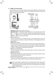
...consists of power switch, reset switch, power LED, hard drive activity LED, speaker and etc. S1 Blinking tem is detected at system startup. The front panel design may issue beeps in S3/S4 sleep S3/S4/S5 Off state or powered off when the system is reading or ... a chassis with a chassis intrusion switch/sensor. RESRES+ CICI+ PWR+ PWR- 7) F_PANEL (Front Panel Header) Connect the power switch, reset switch, speaker, chassis intrusion switch/sensor and system status indicator on the chassis to this header, make sure the wire assignments and the pin assignments are matched...
...consists of power switch, reset switch, power LED, hard drive activity LED, speaker and etc. S1 Blinking tem is detected at system startup. The front panel design may issue beeps in S3/S4 sleep S3/S4/S5 Off state or powered off when the system is reading or ... a chassis with a chassis intrusion switch/sensor. RESRES+ CICI+ PWR+ PWR- 7) F_PANEL (Front Panel Header) Connect the power switch, reset switch, speaker, chassis intrusion switch/sensor and system status indicator on the chassis to this header, make sure the wire assignments and the pin assignments are matched...
