
Manual
Page 1
... array: (Note 3): Click Manual to access the Intel Matrix Storage Console, with a simple click of your needs and hardware components. 3. Using GIGABYTE eXtreme Hard Drive (X.H.D) Instructions:(Note 2) Before launching X.H.D, make sure the newly added harddrive has equal or greater capacity than or equal to set up...the Application Software screen to enhance your hard drive read/write performance without the need for the Intel SATA controllers. B. A. eXtreme Hard Drive (X.H.D) With GIGABYTE eXtreme Hard Drive (X.H.D)(Note 1), users can quickly configure a RAIDready system for RAID 0.
... array: (Note 3): Click Manual to access the Intel Matrix Storage Console, with a simple click of your needs and hardware components. 3. Using GIGABYTE eXtreme Hard Drive (X.H.D) Instructions:(Note 2) Before launching X.H.D, make sure the newly added harddrive has equal or greater capacity than or equal to set up...the Application Software screen to enhance your hard drive read/write performance without the need for the Intel SATA controllers. B. A. eXtreme Hard Drive (X.H.D) With GIGABYTE eXtreme Hard Drive (X.H.D)(Note 1), users can quickly configure a RAIDready system for RAID 0.

Manual
Page 5
... 6...72 4-4 Dynamic Energy Saver™ 2 73 4-5 Q-Share...75 4-6 Smart 6™ ...76 Chapter 5 Appendix...79 5-1 Configuring SATA Hard Drive(s 79 5-1-1 Configuring Intel P55 SATA Controllers 79 5-1-2 Configuring GIGABYTE SATA2 SATA Controller 87 5-1-3 Making a SATA RAID/AHCI Driver Diskette 93 5-1-4 Installing the SATA RAID/AHCI Driver and Operating System 94 5-2 Configuring Audio Input and Output 105 5-2-1 Configuring 2/4/5.1/7.1-Channel...
... 6...72 4-4 Dynamic Energy Saver™ 2 73 4-5 Q-Share...75 4-6 Smart 6™ ...76 Chapter 5 Appendix...79 5-1 Configuring SATA Hard Drive(s 79 5-1-1 Configuring Intel P55 SATA Controllers 79 5-1-2 Configuring GIGABYTE SATA2 SATA Controller 87 5-1-3 Making a SATA RAID/AHCI Driver Diskette 93 5-1-4 Installing the SATA RAID/AHCI Driver and Operating System 94 5-2 Configuring Audio Input and Output 105 5-2-1 Configuring 2/4/5.1/7.1-Channel...
Manual
Page 6
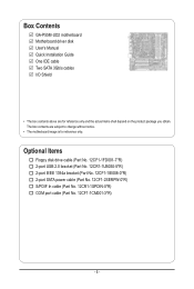
...port IEEE 1394a bracket (Part No. 12CF1-1IE008-0*R) 2-port SATA power cable (Part No. 12CF1-2SERPW-0*R) S/PDIF In cable (Part No. 12CR1-1SPDIN-0*R) COM port cable (Part No. 12CF1-1CM001-3*R) - 6 - Box Contents GA-P55M-UD2 motherboard Motherboard driver disk User's Manual Quick Installation Guide One ...IDE cable Two SATA 3Gb/s cables I/O Shield • The box contents above are subject to change without notice. •...
...port IEEE 1394a bracket (Part No. 12CF1-1IE008-0*R) 2-port SATA power cable (Part No. 12CF1-2SERPW-0*R) S/PDIF In cable (Part No. 12CR1-1SPDIN-0*R) COM port cable (Part No. 12CF1-1CM001-3*R) - 6 - Box Contents GA-P55M-UD2 motherboard Motherboard driver disk User's Manual Quick Installation Guide One ...IDE cable Two SATA 3Gb/s cables I/O Shield • The box contents above are subject to change without notice. •...
Manual
Page 8
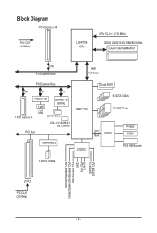
Block Diagram 1 PCI Express x16 PCIe CLK (100 MHz) LGA1156 CPU CPU CLK+/- (133 MHz) DDR3 2200/1333/1066/800 MHz Dual Channel Memory x16 PCI Express Bus DMI Interface PCI Express Bus x4 x1 x1 RTL8111D RJ45 GIGABYTE SATA2 1 PCI Express x4 LAN 2 SATA 3Gb/s ATA-133/100/66/33 IDE Channel PCI Bus TSB43AB23 Intel® P55 CODEC Dual BIOS 6 SATA 3Gb/s 14 USB Ports LPC IT8720 Bus Floppy COM PS/2 KB/Mouse 2 IEEE 1394a Surround Speaker Out Center/Subwoofer Speaker Out Side Speaker Out MIC Line Out Line In S/PDIF In S/PDIF Out 2 PCI PCI CLK (33 MHz) - 8 -
Block Diagram 1 PCI Express x16 PCIe CLK (100 MHz) LGA1156 CPU CPU CLK+/- (133 MHz) DDR3 2200/1333/1066/800 MHz Dual Channel Memory x16 PCI Express Bus DMI Interface PCI Express Bus x4 x1 x1 RTL8111D RJ45 GIGABYTE SATA2 1 PCI Express x4 LAN 2 SATA 3Gb/s ATA-133/100/66/33 IDE Channel PCI Bus TSB43AB23 Intel® P55 CODEC Dual BIOS 6 SATA 3Gb/s 14 USB Ports LPC IT8720 Bus Floppy COM PS/2 KB/Mouse 2 IEEE 1394a Surround Speaker Out Center/Subwoofer Speaker Out Side Speaker Out MIC Line Out Line In S/PDIF In S/PDIF Out 2 PCI PCI CLK (33 MHz) - 8 -

Manual
Page 10
... JBOD w iTE IT8720 chip: - 1 x floppy disk drive connector supporting up to 1 SATA 3Gb/s device - 1-2 Product Specifications CPU w w Support for an Intel® Core™ i7 series processor/Intel® Core™ i5 series processor in the LGA1156 package (Go to GIGABYTE's website for the latest CPU support list.) L3 cache varies with...
... JBOD w iTE IT8720 chip: - 1 x floppy disk drive connector supporting up to 1 SATA 3Gb/s device - 1-2 Product Specifications CPU w w Support for an Intel® Core™ i7 series processor/Intel® Core™ i5 series processor in the LGA1156 package (Go to GIGABYTE's website for the latest CPU support list.) L3 cache varies with...

Manual
Page 11
... brackets connected to the internal IEEE 1394a header) 1 x 24-pin ATX main power connector 1 x 8-pin ATX 12V power connector 1 x floppy disk drive connector 1 x IDE connector 7 x SATA 3Gb/s connectors 1 x CPU fan header 1 x system fan header 1 x front panel header 1 x front panel audio header 1 x CD In connector 1 x S/PDIF In header 1 x S/PDIF Out header 2 x USB...
... brackets connected to the internal IEEE 1394a header) 1 x 24-pin ATX main power connector 1 x 8-pin ATX 12V power connector 1 x floppy disk drive connector 1 x IDE connector 7 x SATA 3Gb/s connectors 1 x CPU fan header 1 x system fan header 1 x front panel header 1 x front panel audio header 1 x CD In connector 1 x S/PDIF In header 1 x S/PDIF Out header 2 x USB...

Manual
Page 19
...Mbps data rate Activity LED: State Description Blinking Data transmission or receiving is occurring Off No data transmission or receiving is compatible with SATA 1.5Gb/s standard. Before using this feature, ensure that your audio system provides a coaxial digital audio in connector. eSATA 3Gb/s Port...supports digital coaxial audio. RJ-45 LAN Port The Gigabit Ethernet LAN port provides Internet connection at up to connect an external SATA device or a SATA port multiplier. Hardware Installation PS/2 Keyboard and PS/2 Mouse Port Use this port for USB devices such as a USB ...
...Mbps data rate Activity LED: State Description Blinking Data transmission or receiving is occurring Off No data transmission or receiving is compatible with SATA 1.5Gb/s standard. Before using this feature, ensure that your audio system provides a coaxial digital audio in connector. eSATA 3Gb/s Port...supports digital coaxial audio. RJ-45 LAN Port The Gigabit Ethernet LAN port provides Internet connection at up to connect an external SATA device or a SATA port multiplier. Hardware Installation PS/2 Keyboard and PS/2 Mouse Port Use this port for USB devices such as a USB ...

Manual
Page 24
... for instructions on the connector. Before attaching the IDE cable, locate the foolproof groove on configuring a RAID array. Pin No. Hardware Installation - 24 - Each SATA connector supports a single SATA device. Definition SATA2_3 7 7 SATA2_4 SATA2_2 7 1 1 SATA2_1 2 1 3 14 SATA2_0 5 6 7 GND TXP TXN GND RXN RXP GND • A RAID...you wish to connect two IDE devices, remember to set the jumpers and the cabling according to the role of the SATA 3Gb/s cable to SATA 3Gb/s standard and are to be used, the total number of hard drives does not have to be an even number...
... for instructions on the connector. Before attaching the IDE cable, locate the foolproof groove on configuring a RAID array. Pin No. Hardware Installation - 24 - Each SATA connector supports a single SATA device. Definition SATA2_3 7 7 SATA2_4 SATA2_2 7 1 1 SATA2_1 2 1 3 14 SATA2_0 5 6 7 GND TXP TXN GND RXN RXP GND • A RAID...you wish to connect two IDE devices, remember to set the jumpers and the cabling according to the role of the SATA 3Gb/s cable to SATA 3Gb/s standard and are to be used, the total number of hard drives does not have to be an even number...

Manual
Page 25
...battery provides power to keep the values (such as BIOS configurations, date, and time information) in accordance with SATA 1.5Gb/s standard. Turn off . The GIGABYTE SATA2 controller supports RAID 0 and RAID 1. You may be an even number. Replace the battery when the ...battery is turned off your - Each SATA connector supports a single SATA device. Gently remove the battery from the battery holder and wait for one . 8) GSATA2_0/1 (SATA 3Gb/s Connectors, Controlled by GIGABYTE SATA2, White) The SATA connectors conform to SATA 3Gb/s standard and are compatible with local...
...battery provides power to keep the values (such as BIOS configurations, date, and time information) in accordance with SATA 1.5Gb/s standard. Turn off . The GIGABYTE SATA2 controller supports RAID 0 and RAID 1. You may be an even number. Replace the battery when the ...battery is turned off your - Each SATA connector supports a single SATA device. Gently remove the battery from the battery holder and wait for one . 8) GSATA2_0/1 (SATA 3Gb/s Connectors, Controlled by GIGABYTE SATA2, White) The SATA connectors conform to SATA 3Gb/s standard and are compatible with local...

Manual
Page 34
Motherboard Model BIOS Version P55M-UD2 D8 . . . . : BIOS Setup : XpressRecovery2 : Boot Menu : Qflash 07/16/2009-P55-7A89RG0EC-00 Function Keys Function Keys SATA Mode Message: "SATA is running at IDE mode. When the motherboard is set the first boot device without having to access the Q-Flash utility .... After system restart, the device boot order will directly boot from the device configured in BIOS Setup. : XPRESS RECOVERY2 If you the SATA controller is found running at IDE MODE!" To show the BIOS POST screen. A. The POST Screen Award Modular BIOS v6.00PG, An ...
Motherboard Model BIOS Version P55M-UD2 D8 . . . . : BIOS Setup : XpressRecovery2 : Boot Menu : Qflash 07/16/2009-P55-7A89RG0EC-00 Function Keys Function Keys SATA Mode Message: "SATA is running at IDE mode. When the motherboard is set the first boot device without having to access the Q-Flash utility .... After system restart, the device boot order will directly boot from the device configured in BIOS Setup. : XPRESS RECOVERY2 If you the SATA controller is found running at IDE MODE!" To show the BIOS POST screen. A. The POST Screen Award Modular BIOS v6.00PG, An ...

Manual
Page 36
..., advanced features available on the CPU, and the primary display adapter. Integrated Peripherals Use this menu to configure all peripheral devices, such as IDE, SATA, USB, integrated audio, and integrated LAN, etc. Power Management Setup Use this menu to see information about autodetected system/CPU temperature, system voltage and...
..., advanced features available on the CPU, and the primary display adapter. Integrated Peripherals Use this menu to configure all peripheral devices, such as IDE, SATA, USB, integrated audio, and integrated LAN, etc. Power Management Setup Use this menu to see information about autodetected system/CPU temperature, system voltage and...

Manual
Page 47
Time (hh:mm:ss) Sets the system time. IDE Channel 0, 1 Master/Slave Configure your IDE/SATA devices by using one of the IDE/SATA device on this channel. The date format is 13:0:0. For example, 1 p.m. BIOS Setup Select the desired field and use the up arrow or down arrow ...
Time (hh:mm:ss) Sets the system time. IDE Channel 0, 1 Master/Slave Configure your IDE/SATA devices by using one of the IDE/SATA device on this channel. The date format is 13:0:0. For example, 1 p.m. BIOS Setup Select the desired field and use the up arrow or down arrow ...

Manual
Page 48
...2M/5.25", 720K/3.5", 1.44M/3.5", 2.88M/3.5". IDE Channel 2, 3 Master, 4, 5 Master/Slave IDE Auto-Detection Press to autodetect the parameters of the IDE/SATA device on the hard drive. The following fields display your system. Landing Zone Landing zone. Options are : Auto (default), CHS, LBA, Large. If ... Memory The total amount of heads. Drive A Allows you to None. BIOS Setup - 48 - Extended IDE Drive Configure your IDE/SATA devices by the BIOS POST. Access Mode Sets the hard drive access mode. Sector Number of extended memory. • Auto Lets the...
...2M/5.25", 720K/3.5", 1.44M/3.5", 2.88M/3.5". IDE Channel 2, 3 Master, 4, 5 Master/Slave IDE Auto-Detection Press to autodetect the parameters of the IDE/SATA device on the hard drive. The following fields display your system. Landing Zone Landing zone. Options are : Auto (default), CHS, LBA, Large. If ... Memory The total amount of heads. Drive A Allows you to None. BIOS Setup - 48 - Extended IDE Drive Configure your IDE/SATA devices by the BIOS POST. Access Mode Sets the hard drive access mode. Sector Number of extended memory. • Auto Lets the...

Manual
Page 51
...: Enabled) - 51 - Disabled Allows the SATA controllers to IDE mode. (Default) RAID Enables RAID for the SATA controllers. BIOS Setup Disabled Disables RAID for the SATA controllers and configures the SATA controllers to operate in Legacy IDE mode. Advanced...USB Legacy Function USB Storage Function Azalia Codec Onboard H/W 1394 Onboard H/W LAN Green LAN } SMART LAN Onboard LAN Boot ROM Onboard SATA/IDE Device Onboard SATA/IDE Ctrl Mode Onboard Serial Port 1 [Disabled] [Enabled] [Enabled] [Enabled] [Enabled] [Auto] [Enabled] [Enabled] [Disabled...
...: Enabled) - 51 - Disabled Allows the SATA controllers to IDE mode. (Default) RAID Enables RAID for the SATA controllers. BIOS Setup Disabled Disables RAID for the SATA controllers and configures the SATA controllers to operate in Legacy IDE mode. Advanced...USB Legacy Function USB Storage Function Azalia Codec Onboard H/W 1394 Onboard H/W LAN Green LAN } SMART LAN Onboard LAN Boot ROM Onboard SATA/IDE Device Onboard SATA/IDE Ctrl Mode Onboard Serial Port 1 [Disabled] [Enabled] [Enabled] [Enabled] [Enabled] [Auto] [Enabled] [Enabled] [Disabled...

Manual
Page 53
...with the onboard LAN chip. (Default: Disabled) Onboard SATA/IDE Device (GIGABYTE SATA2, IDE and GSATA2_0/1 Connectors) Enables or disables the IDE and SATA controllers integrated in the GIGABYTE SATA2 chip. (Default: Enabled) Onboard SATA/IDE Ctrl Mode (GIGABYTE SATA2, IDE and GSATA2_0/1 Connectors) Enables or disables ... to the fault or short. If a cable problem occurs on Part 1-2. the IDE controller still operates in the GIGABYTE SATA2 chip or configures the SATA controller to AHCI mode. Onboard Serial Port 1 Enables or disables the first serial port and specifies its base I/O ...
...with the onboard LAN chip. (Default: Disabled) Onboard SATA/IDE Device (GIGABYTE SATA2, IDE and GSATA2_0/1 Connectors) Enables or disables the IDE and SATA controllers integrated in the GIGABYTE SATA2 chip. (Default: Enabled) Onboard SATA/IDE Ctrl Mode (GIGABYTE SATA2, IDE and GSATA2_0/1 Connectors) Enables or disables ... to the fault or short. If a cable problem occurs on Part 1-2. the IDE controller still operates in the GIGABYTE SATA2 chip or configures the SATA controller to AHCI mode. Onboard Serial Port 1 Enables or disables the first serial port and specifies its base I/O ...

Manual
Page 65
... Click Drive options. Chapter 4 Unique Features 4-1 Xpress Recovery2 Xpress Recovery2 is recommended; actual size requirements vary, depending on the first SATA connector is backed up/ restored. • It takes longer to leave enough unallocated space in the following sequence: The first PATA IDE... connector, the second PATA IDE connector, the first SATA connector, the second SATA connector and so forth. Unique Features System Requirements: • At least 512 MB of system memory • VESA compatible...
... Click Drive options. Chapter 4 Unique Features 4-1 Xpress Recovery2 Xpress Recovery2 is recommended; actual size requirements vary, depending on the first SATA connector is backed up/ restored. • It takes longer to leave enough unallocated space in the following sequence: The first PATA IDE... connector, the second PATA IDE connector, the first SATA connector, the second SATA connector and so forth. Unique Features System Requirements: • At least 512 MB of system memory • VESA compatible...

Manual
Page 68
...backup BIOS manually. p55mud2.f1) to enter MS-DOS mode. P55M-UD2 D8 . . . . : BIOS Setup : XpressRecovery2 : Boot Menu : Qflash 07/16/2009-P55-7A89RG0EC-00 Because BIOS flashing is DualBIOS™? Before You Begin 1. From GIGABYTE's website, download the latest compressed BIOS update file that support DualBIOS...the BIOS file to the main BIOS to access Q-Flash. Restart the system. During the POST, press the key to an independent IDE/SATA controller, use FAT32/16/12 file system. 3. Unique Features - 68 - What is corrupted or damaged, the backup BIOS will download ...
...backup BIOS manually. p55mud2.f1) to enter MS-DOS mode. P55M-UD2 D8 . . . . : BIOS Setup : XpressRecovery2 : Boot Menu : Qflash 07/16/2009-P55-7A89RG0EC-00 Because BIOS flashing is DualBIOS™? Before You Begin 1. From GIGABYTE's website, download the latest compressed BIOS update file that support DualBIOS...the BIOS file to the main BIOS to access Q-Flash. Restart the system. During the POST, press the key to an independent IDE/SATA controller, use FAT32/16/12 file system. 3. Unique Features - 68 - What is corrupted or damaged, the backup BIOS will download ...

Manual
Page 69
... file system. • If the BIOS update file is saved to a hard drive in RAID/AHCI mode or a hard drive attached to an independent IDE/SATA controller, use the up or down arrow key to select Update BIOS from the floppy disk is complete, press any key to return to access...
... file system. • If the BIOS update file is saved to a hard drive in RAID/AHCI mode or a hard drive attached to an independent IDE/SATA controller, use the up or down arrow key to select Update BIOS from the floppy disk is complete, press any key to return to access...

Manual
Page 77
... daily backup (Note 3) Sets a daily backup schedule Sets the percentage of hard drive space used for copying files/folders from a specific backup on PATA and SATA hard drives (partitioned on NTFS file system) in case the system/hard drive fails. If you want to launch the SMART DualBIOS utility. The files...
... daily backup (Note 3) Sets a daily backup schedule Sets the percentage of hard drive space used for copying files/folders from a specific backup on PATA and SATA hard drives (partitioned on NTFS file system) in case the system/hard drive fails. If you want to launch the SMART DualBIOS utility. The files...

Manual
Page 79
.../AHCI driver and operating system. (Note 2) Before you begin Please prepare: • At least two SATA hard drives (to create RAID, you may prepare only one end of the SATA signal cable to the rear of the SATA hard drive and the other end to AHCI or RAID mode. - 79 - C. Make a floppy... drive(s), follow the steps below: A. If you use two hard drives with identical model and capacity). Installing SATA hard drive(s) in your computer. B. Install SATA hard drive(s) in your power supply to the hard drive. (Note 1) Skip this step if you do not want to create RAID array. (Note 2) ...
.../AHCI driver and operating system. (Note 2) Before you begin Please prepare: • At least two SATA hard drives (to create RAID, you may prepare only one end of the SATA signal cable to the rear of the SATA hard drive and the other end to AHCI or RAID mode. - 79 - C. Make a floppy... drive(s), follow the steps below: A. If you use two hard drives with identical model and capacity). Installing SATA hard drive(s) in your computer. B. Install SATA hard drive(s) in your power supply to the hard drive. (Note 1) Skip this step if you do not want to create RAID array. (Note 2) ...


