Gigabyte GA-7PESH2 Support Question
Gigabyte GA-7PESH2 Support Question
Find answers below for this question about Gigabyte GA-7PESH2.Need a Gigabyte GA-7PESH2 manual? We have 1 online manual for this item!
Question posted by xragusin on December 25th, 2013
Try To Install Win7x64 From Usb Key. Sata Hd Not Found Once Ahci Driver Loaded
using latest available driver from server_driver_sata_v3.0.0.3020 package more precisely the stuff from "RSTe f6 Drivers Staging\iaStorA.free.64bit.3.0.0.3011" going to advanced mode, browsing to load the driver above; The installer found compatible driver "Intel C600 series chipset SATA/AHCI" but once the driver loaded no HD found ...Physicaly, the server has 2 WD SATA HD Currently the BIOS setting are AHCI - not RAID mode
Current Answers
Answer #1: Posted by TommyKervz on December 26th, 2013 12:48 AM
TommyKervz

Member since:
January 10th, 2013 Points: 17,776,813

Member since:
January 10th, 2013 Points: 17,776,813
Greetings. I remember having the same result (HDD not found) with the BIOS set to AHCI. Changing it to SATA solved that and the HDD showed up.
Go here and see CHANGING FROM “AHCI” TO “ATA”
Related Gigabyte GA-7PESH2 Manual Pages
Manual - Page 2

Disclaimer Information in the use of this manual is protected by copyright laws and is the property of the product, read the Quick Installation Guide included with the product. For detailed product information, carefully read the User's Manual. Documentation Classifications In order to assist in this product, GIGABYTE ...
Manual - Page 6

...
Code
1 SW1
2 MLAN (GA-7PESH1)
USB_MLAN (GA-7PESH2)
3 USB_LAN1 (GA-7PESH1)
GLAN1 (GA-7PESH2)
4 USB_LAN2 (GA-7PESH1)
GLAN2 (GA-7PESH2)
5 VGA_1
6 COM1
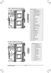
7 ...SATA SGPIO connector Mini SAS cable connector Mini SAS cable connector Flash descriptor security jumper Mini SAS cable connector (SATA 3.0Gb/s signal) SATA 6.0Gb/s connectors HDD back plane connector System fan cable connector Front USB...
Manual - Page 7
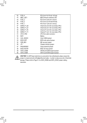
Please refer to reduce any risk of hard disk damage. If a SATA type hard drive is connected to the motherboard, please ensure the jumper is closed and set to 2-3 pins (Normal mode), in order to Page 33 for secondary CPU) CPU1 fan cable connector Battery Clear CMOS jumper BIOS write protect jumper ME recovery...
Manual - Page 9

... in the LGA2011 package
ŠŠ ...RSTe SATA RAID 0, RAID 1
USB
ŠŠ Up to 6 USB 2.0/1.1 ports (4 on the back panel, 2 additional ports via the USB
brackets connected to the internal USB headers/GA-7PESH1)
ŠŠ Up to 4 USB 2.0/1.1 ports (2 on the back panel, 2 additional ports via the USB
brackets connected to the internal USB headers/GA-7PESH2)
- 9 - Hardware Installation...
Manual - Page 10

... signal) ŠŠ 1 x Mini SAS connector (SATA 3Gb/s signal) ŠŠ 2 x SATA 6Gb/s connectors ŠŠ 1 x PSMI header Š...USB 2.0/1.1 header ŠŠ 1 x TPM header ŠŠ 1 x SKU KEY header ŠŠ 1 x SPGIO header ŠŠ 4 x USB 2.0/1.1 ports (GA-7PESH1) ŠŠ 2 x USB 2.0/1.1 ports (GA-7PESH2... on
the CPU/system cooler you install. ŠŠ 1 x 64...
Manual - Page 11

... CPU host frequency in accordance with the CPU specifications. Hardware Installation Locate the alignment keys on the motherboard CPU socket and the notches on the CPU
Notch
Notch
- 11 - Pin One Corner of the CPU. It is not recommended
that the motherboard supports the CPU.
(Go to GIGABYTE's website for the peripherals. The CPU cannot...
Manual - Page 12
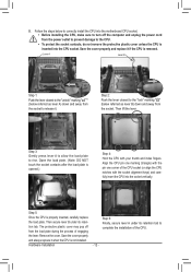
... plastic cover unless the CPU is inserted into the motherboard CPU socket. •• Before installing the CPU, make sure to rise. Open the load plate. (Note: DO NOT touch the socket contacts after the load plate is removed. Step 5: Once the CPU is not installed. Save the cover properly and replace it when the...
Manual - Page 14
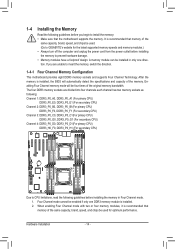
... BIOS will be installed in Four Channel mode. 1. 1-4 Installing the Memory
Read the following guidelines before installing the memory in only one DDR3 memory module is recommended that the motherboard supports the memory. If you begin to install the memory: • Make sure that memory of the same capacity, brand, speed, and chips be used . (Go to GIGABYTE...
Manual - Page 16

... Gigabit Ethernet LAN port provides Internet connection at up to 1 Gbps data rate. 1-5 Back Panel Connectors
GA-7PESH1
GA-7PESH2
Serial Port Connects to video loop thru function. Use this port for USB devices such as a USB keyboard/mouse, USB printer, USB flash drive and etc.
KVM Server Management 10/100 LAN Port The LAN port provides Internet...
Manual - Page 22

... 7 8 9 10
Definition Power (5V) Power (5V) USB DXUSB DYUSB DX+ USB DY+ GND GND No Pin NC
Hardware Installation
- 22 - If more than two hard drives are configured, ...requires at least two hard drives.
Each USB header can provide two USB ports via an optional USB bracket. Each SATA connector supports a single SATA device. When SATA_DOM1/2 jumper are set to Normal Mode:
SATA0 SATA1
7
7
1
1
...
Manual - Page 23

... B14 B15 B16 B17 A18
Definition GND TX0+ TX0GND TX1+ TX1GND SIB0 SIB1 SIB2 SIB6 GND TX2+ TX2GND TX3+ TX3GND
Hardware Installation A1 B1
MINI_CN1 MINI_CN2
A18 B18
MINI_CN3
MINI_CN1
Pin No.
Each SATA connector supports two SATA device.
12/13) MINI_CN2/MINI_CN3 (Mini SAS cable connectors) The mini SAS connectors conform to...
Manual - Page 24
...
1 AST2300_SCGCLK
2 FM_THROTTLE_AND_N
12
3 AST2300_SGLD
4 IQO_FAN_12v_GATE_N
5 AST2300_SGDOUT
6 GND
7 KEY
8 RresetL_BRB
9 GND
10 BP_ALED_N
25 26
11 BP_LED_G_N
12 GND
13 AST2300_SGDIN
14...17 GND
18 SMB_BPB1_CLK
19 P_3V3_AUX
20 BP_HDD_TYPE
21 P_3V3_AUX
22 FAN_TYPE
23 GND
24 KEY
25 BP_PRESENSE
26 GND
Pin No. Definition
1 CLK_33M_TPM
2 P_3V3_AUX
12
3 LPC_RST_DEBUG
...
Manual - Page 25

...assignments are
matched correctly. - 25 -
Hard Disk LED Signal cathode(-)
10 SYS_STATUS- Hardware Installation
Signal Name
Definition
1 PWLED+
Power LED Signal anode (+)
2 5VSB
5V Stanndby Power
3 ...CASE_OPEN- ID LED Signal cathode(-)
7 HD+
Hard Disk LED Signal anode (+)
8 F_SYSRDY
System Front board LED Signal
9 HD- LAN2 Link LED Signal cathode(-)
The front...
Manual - Page 26

...GND
6 SGPIO_SATA_LOAD
7 NC
8 SGPIO_SATA_CLOCK
Hardware Installation
- 26 - 17) IPMB1 (IPMB connector)
3
Pin No. Definition
1 SCL
2 GND
1
3 SDA
18) SATA_SGPIO (SATA SGPIO Header)
SGPIO is stands for Serial ...General Purpose Input/Output which is driven by the HBA and 1 is a 4-signal (or 4-wire) bus used between a Host ...
Manual - Page 30

... place a jumper cap on the two pins to temporarily short the two pins or use a metal object like a screwdriver to touch the two pins for a few seconds.... write protect function.
Hardware Installation
- 30 - Failure to do so may cause damage to the motherboard.
• After system restart, go to BIOS Setup Exit menu and load factory defaults (select Load Default Values) or manually configure...
Manual - Page 32

Hardware Installation
- 32 - 5) PASSWORD1 (Skip Supervisor Password Jumper)
1 1-2 Close: Normal operation. (Default setting)
1 2-3 Close: Skip supervisor password.
6) BIOS_RVCR1 (BIOS Recovery Jumper)
1 1-2 Close: Normal operation. (Default setting)
1 2-3 Close: BIOS recovery mode.
Manual - Page 33
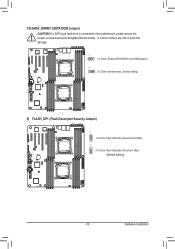
... Jumper) CAUTION!
Hardware Installation If a SATA type hard drive is connected to the motherboard, please ensure the jumper is closed and set to 2-3 pins (Normal mode), in order to reduce any risk of hard disk damage.
1 1-2 Close: Enable SATA0/SATA1 port DOM support.
1 2-3 Close: Normal mode. (Default setting)
9) FLASH_DP1 (Flash Descriptor Security Jumper)
1 1-2 Close: Flash...
Manual - Page 34
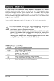
... Setup
- 34 - To access the BIOS Setup program, press the key during system startup, saving system parameters and loading operating system, etc. Chapter 2 BIOS Setup
BIOS (Basic Input and Output System) records hardware parameters of the system in the EFI on the motherboard supplies the necessary power to the CMOS to keep the...
Manual - Page 46

.... Default setting is AHCI Mode.
(Note) This item is will be access the RAID setup utility at boot time. SATA Mode
Select the on chip SATA type. Options available: IDE/RAID/AHCI/Disabled. RAID Mode: When set to RAID, the SATA controllerenables both its RAID and AHCI functions. 2-2-5 SATA Configuration
SATA Port 0/1/2/3/4/5 (Note)
Displays the installed HDD devices information...
Manual - Page 50

... Disabled. Flow Control
Flow control can be used for error detection. Terminal Type
Select a terminal type to IT8728 SOL UART. Options available: VT100/VT100+/ANSI /VT-UTF8. Mark and Space Parity do not allow for console redirection. Default setting is always 0. Options available: Enabled/Disabled.
(Note) Advanced items prompt when this item is 1 stop...
Similar Questions

Com Header Port Not Working
New MB using com header with cable and 9 pin cponnector. Bios set up for com1 active.Device set to u...
New MB using com header with cable and 9 pin cponnector. Bios set up for com1 active.Device set to u...
(Posted by e2wentzel 2 years ago)

Is Possible To Set A Raid On This Motherboard?
(Posted by ivanpalmam 2 years ago)
Windows 7 Is Not Installing
When i try to install windows ,it takes 15 min to loading windows files and after choose the hard to...
When i try to install windows ,it takes 15 min to loading windows files and after choose the hard to...
(Posted by mory20132013 8 years ago)

Can't Install Sata 3.0 Driver Windows 7 X64
SATA 3 SSD drive only runs at 2.0 speed. Windows 7 won't let me install the SATA 3.0 driver.
SATA 3 SSD drive only runs at 2.0 speed. Windows 7 won't let me install the SATA 3.0 driver.
(Posted by sxoghie 11 years ago)

Pls. Send Me A Pdf Wiring Installation Guide For My Motherboard Ga-h61m-ds2..thn
(Posted by DAVIDJR1261 11 years ago)