
Manual
Page 1
... launching X.H.D, make sure the new drive is greater than or equal to load the SATA controller driver first. A. To automatically set up all motherboard drivers, including the X.H.D utility. For a RAID 0 array that already exists, users also can use X.H.D to easily add a hard drive ...array later using the Auto function. The following procedure details the steps to set up a RAID 0 array. 2. eXtreme Hard Drive (X.H.D) With GIGABYTE eXtreme Hard Drive (X.H.D)(Note 1), users can quickly configure a RAIDready system for the Intel SATA controllers. Setting Up a RAID-Ready System Step 1:...
... launching X.H.D, make sure the new drive is greater than or equal to load the SATA controller driver first. A. To automatically set up all motherboard drivers, including the X.H.D utility. For a RAID 0 array that already exists, users also can use X.H.D to easily add a hard drive ...array later using the Auto function. The following procedure details the steps to set up a RAID 0 array. 2. eXtreme Hard Drive (X.H.D) With GIGABYTE eXtreme Hard Drive (X.H.D)(Note 1), users can quickly configure a RAIDready system for the Intel SATA controllers. Setting Up a RAID-Ready System Step 1:...

Manual
Page 4
Some motherboard driver disks include the Smart TPM utility in "Xpress Install." Click the Install All button and "Xpress Install" will automatically scan your system and list ... the tab at the bottom of the left pane of the selected drivers, including the Infineon TPM driver. 2.2. Installing the Infineon TPM Driver Insert the GIGABYTE motherboard driver disk. Click the Install button on the "Xpress Install" main menu to install it. Click the "Install All" button on the right of the...
Some motherboard driver disks include the Smart TPM utility in "Xpress Install." Click the Install All button and "Xpress Install" will automatically scan your system and list ... the tab at the bottom of the left pane of the selected drivers, including the Infineon TPM driver. 2.2. Installing the Infineon TPM Driver Insert the GIGABYTE motherboard driver disk. Click the Install button on the "Xpress Install" main menu to install it. Click the "Install All" button on the right of the...

Manual
Page 7
... key, make sure your cell phone. Step 3: Create Your Smart TPM Key 1. Then enter the same passkey on your cell phone for pairing with your motherboard includes a Bluetooth receiver and turn on the search and Bluetooth functions on the left will be used for pairing. Upon completing the steps above, click...
... key, make sure your cell phone. Step 3: Create Your Smart TPM Key 1. Then enter the same passkey on your cell phone for pairing with your motherboard includes a Bluetooth receiver and turn on the search and Bluetooth functions on the left will be used for pairing. Upon completing the steps above, click...

Manual
Page 19
...'t display your Bluetooth-enabled cell phone, click Refresh to let Smart TPM re-detect the device.) Before creating a Bluetooth cell phone key, make sure your motherboard includes a Bluetooth receiver and turn off or reset your computer when a USB key is being created. • If you enter the TPM User Password incorrectly...
...'t display your Bluetooth-enabled cell phone, click Refresh to let Smart TPM re-detect the device.) Before creating a Bluetooth cell phone key, make sure your motherboard includes a Bluetooth receiver and turn off or reset your computer when a USB key is being created. • If you enter the TPM User Password incorrectly...
Manual
Page 1
GA-P55A-UD5 LGA1156 socket motherboard for Intel® Core™ i7 processor family/ Intel® Core™ i5 processor family User's Manual Rev. 1002 12ME-P55AUD5-1002R
GA-P55A-UD5 LGA1156 socket motherboard for Intel® Core™ i7 processor family/ Intel® Core™ i5 processor family User's Manual Rev. 1002 12ME-P55AUD5-1002R
Manual
Page 2
Motherboard GA-P55A-UD5 Oct. 16, 2009 Motherboard GA-P55A-UD5 Oct. 16, 2009
Motherboard GA-P55A-UD5 Oct. 16, 2009 Motherboard GA-P55A-UD5 Oct. 16, 2009
Manual
Page 3
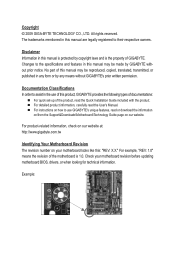
... with the product. All rights reserved. For example, "REV: 1.0" means the revision of the motherboard is the property of GIGABYTE. No part of this product, GIGABYTE provides the following types of documentations: For quick set-up of this manual may be reproduced, copied...published in this manual may be made by GIGABYTE without GIGABYTE's prior written permission. For detailed product information, carefully read the User's Manual. Example: The trademarks mentioned in any means without prior notice. Check your motherboard looks like this manual is protected by ...
... with the product. All rights reserved. For example, "REV: 1.0" means the revision of the motherboard is the property of GIGABYTE. No part of this product, GIGABYTE provides the following types of documentations: For quick set-up of this manual may be reproduced, copied...published in this manual may be made by GIGABYTE without GIGABYTE's prior written permission. For detailed product information, carefully read the User's Manual. Example: The trademarks mentioned in any means without prior notice. Check your motherboard looks like this manual is protected by ...
Manual
Page 4
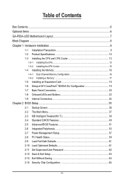
Table of Contents Box Contents...6 Optional Items...6 GA-P55A-UD5 Motherboard Layout 7 Block Diagram...8 Chapter 1 Hardware Installation 9 1-1 Installation Precautions 9 1-2 Product Specifications 10 1-3 Installing the CPU and CPU Cooler 13 1-3-1 Installing the CPU 13 1-3-2 Installing the CPU ...
Table of Contents Box Contents...6 Optional Items...6 GA-P55A-UD5 Motherboard Layout 7 Block Diagram...8 Chapter 1 Hardware Installation 9 1-1 Installation Precautions 9 1-2 Product Specifications 10 1-3 Installing the CPU and CPU Cooler 13 1-3-1 Installing the CPU 13 1-3-2 Installing the CPU ...
Manual
Page 6
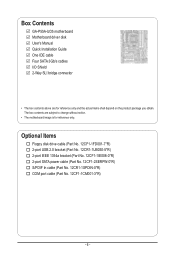
.... 12CF1-2SERPW-0*R) S/PDIF In cable (Part No. 12CR1-1SPDIN-0*R) COM port cable (Part No. 12CF1-1CM001-3*R) - 6 - The box contents are for reference only. Box Contents GA-P55A-UD5 motherboard Motherboard driver disk User's Manual Quick Installation Guide One IDE cable Four SATA 3Gb/s cables I/O Shield 2-Way SLI bridge connector • The box contents above are...
.... 12CF1-2SERPW-0*R) S/PDIF In cable (Part No. 12CR1-1SPDIN-0*R) COM port cable (Part No. 12CF1-1CM001-3*R) - 6 - The box contents are for reference only. Box Contents GA-P55A-UD5 motherboard Motherboard driver disk User's Manual Quick Installation Guide One IDE cable Four SATA 3Gb/s cables I/O Shield 2-Way SLI bridge connector • The box contents above are...
Manual
Page 7
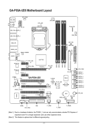
GA-P55A-UD5 Motherboard Layout KB_USB SYS_FAN3 R_SPDIF ATX_12V_2X USB_1394_ESATA_2 USB_1394_ESATA_1 CPU_LED LGA1156 CPU_FAN Phase LED PWR_FAN DIMM_LED IDE_LED USB_LAN MD1 GD1 MD2 GD2 USB30_LAN IDE JMicron JMB362 NEC AUDIO F_AUDIO PCIEX1_1 (Note 1) PE1_LED RTL8111D PCH_FAN RTL8111D PCIEX1_2 Intel® P55 PCIEX16_1 CODEC PCI1 GA-P55A-UD5 SPDIF_I CD_IN PCIEX8_1 SPDIF_O PCI2 TPM_IC(Note 2) PCI_LED DDR3_2 DDR3_1 DDR3_4...
GA-P55A-UD5 Motherboard Layout KB_USB SYS_FAN3 R_SPDIF ATX_12V_2X USB_1394_ESATA_2 USB_1394_ESATA_1 CPU_LED LGA1156 CPU_FAN Phase LED PWR_FAN DIMM_LED IDE_LED USB_LAN MD1 GD1 MD2 GD2 USB30_LAN IDE JMicron JMB362 NEC AUDIO F_AUDIO PCIEX1_1 (Note 1) PE1_LED RTL8111D PCH_FAN RTL8111D PCIEX1_2 Intel® P55 PCIEX16_1 CODEC PCI1 GA-P55A-UD5 SPDIF_I CD_IN PCIEX8_1 SPDIF_O PCI2 TPM_IC(Note 2) PCI_LED DDR3_2 DDR3_1 DDR3_4...

Manual
Page 9
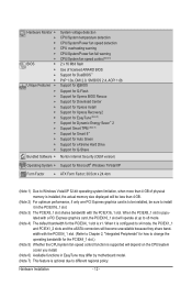
...allow screws to come in a high-temperature environment. • Turning on the computer power during the installation process can become damaged as a motherboard, CPU or memory. These stickers are required for warranty validation. • Always remove the AC power by your hardware components are no ...to installation, carefully read the user's manual and follow these procedures: • Prior to installation, do not remove or break motherboard S/N (Serial Number) sticker or warranty sticker provided by unplugging the power cord from the power outlet before installing or removing the...
...allow screws to come in a high-temperature environment. • Turning on the computer power during the installation process can become damaged as a motherboard, CPU or memory. These stickers are required for warranty validation. • Always remove the AC power by your hardware components are no ...to installation, carefully read the user's manual and follow these procedures: • Prior to installation, do not remove or break motherboard S/N (Serial Number) sticker or warranty sticker provided by unplugging the power cord from the power outlet before installing or removing the...
Manual
Page 12
.... (Note 2) For optimum performance, if only one PCI Express graphics card is to be installed, be sure to install it in EasyTune may differ by motherboard model. (Note 7) This feature is optional due to different regional policy. When the PCIEX8_1 slot is popu lated with the PCIEX4_1 slot. (Refer to Chapter...
.... (Note 2) For optimum performance, if only one PCI Express graphics card is to be installed, be sure to install it in EasyTune may differ by motherboard model. (Note 7) This feature is optional due to different regional policy. When the PCIEX8_1 slot is popu lated with the PCIEX4_1 slot. (Refer to Chapter...

Manual
Page 13
... standard requirements for the latest CPU support list.) • Always turn on the computer if the CPU cooler is not recommended that the motherboard supports the CPU. (Go to GIGABYTE's website for the peripherals. The CPU cannot be inserted if oriented incorrectly. (Or you wish to set beyond the standard specifications, please...
... standard requirements for the latest CPU support list.) • Always turn on the computer if the CPU cooler is not recommended that the motherboard supports the CPU. (Go to GIGABYTE's website for the peripherals. The CPU cannot be inserted if oriented incorrectly. (Or you wish to set beyond the standard specifications, please...

Manual
Page 14
... prevent damage to the "REMOVE" mark) and then remove the cover. (DO NOT touch socket contacts. Step 5: Push the CPU socket lever back into the motherboard CPU socket. B. Before installing the CPU, make sure the front end of the socket cover and use the other to correctly install the CPU into...
... prevent damage to the "REMOVE" mark) and then remove the cover. (DO NOT touch socket contacts. Step 5: Push the CPU socket lever back into the motherboard CPU socket. B. Before installing the CPU, make sure the front end of the socket cover and use the other to correctly install the CPU into...

Manual
Page 15
... Place the cooler atop the CPU, aligning the four push pins through the pin holes on the motherboard. If the push pin is inserted as the example cooler.) Direction of the Arrow Sign on the...Push Pin Step 1: Apply an even and thin layer of thermal grease on the surface of the motherboard. Inadequately removing the CPU cooler may adhere to the CPU. 1-3-2 Installing the CPU Cooler Follow the... attach the power connector of the CPU cooler to correctly install the CPU cooler on the motherboard. (The following procedure uses Intel® boxed cooler as the picture above shows, the ...
... Place the cooler atop the CPU, aligning the four push pins through the pin holes on the motherboard. If the push pin is inserted as the example cooler.) Direction of the Arrow Sign on the...Push Pin Step 1: Apply an even and thin layer of thermal grease on the surface of the motherboard. Inadequately removing the CPU cooler may adhere to the CPU. 1-3-2 Installing the CPU Cooler Follow the... attach the power connector of the CPU cooler to correctly install the CPU cooler on the motherboard. (The following procedure uses Intel® boxed cooler as the picture above shows, the ...
Manual
Page 16
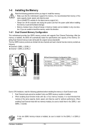
...DS=Double-Sided, "- -"=No Memory) DDR3_2 DDR3_1 DDR3_4 DDR3_3 Due to CPU limitations, read the following guidelines before installing the memory to GIGABYTE's website for optimum performance. A memory module can be installed in the DDR3_1 and DDR3_ 3 sockets. Enabling Dual Channel memory mode will ...same capacity, brand, speed, and chips be sure to insert the memory, switch the direction. 1-4-1 Dual Channel Memory Configuration This motherboard provides four DDR3 memory sockets and supports Dual Channel Technology. The four DDR3 memory sockets are unable to install them in only ...
...DS=Double-Sided, "- -"=No Memory) DDR3_2 DDR3_1 DDR3_4 DDR3_3 Due to CPU limitations, read the following guidelines before installing the memory to GIGABYTE's website for optimum performance. A memory module can be installed in the DDR3_1 and DDR3_ 3 sockets. Enabling Dual Channel memory mode will ...same capacity, brand, speed, and chips be sure to insert the memory, switch the direction. 1-4-1 Dual Channel Memory Configuration This motherboard provides four DDR3 memory sockets and supports Dual Channel Technology. The four DDR3 memory sockets are unable to install them in only ...

Manual
Page 17
..., make sure to turn off the computer and unplug the power cord from the power outlet to prevent damage to install DDR3 DIMMs on this motherboard. Spread the retaining clips at both ends of the memory, push down on the socket. DDR3 and DDR2 DIMMs are not compatible to each other...
..., make sure to turn off the computer and unplug the power cord from the power outlet to prevent damage to install DDR3 DIMMs on this motherboard. Spread the retaining clips at both ends of the memory, push down on the socket. DDR3 and DDR2 DIMMs are not compatible to each other...
Manual
Page 18
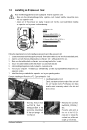
... expansion slot. 1. Make sure the metal contacts on the top edge of the PCI Express slot to install an expansion card: • Make sure the motherboard supports the expansion card. Turn on the slot and then lift the card straight out from the slot. If necessary, go to BIOS Setup to...
... expansion slot. 1. Make sure the metal contacts on the top edge of the PCI Express slot to install an expansion card: • Make sure the motherboard supports the expansion card. Turn on the slot and then lift the card straight out from the slot. If necessary, go to BIOS Setup to...

Manual
Page 19
... and PCIEX8_1 slots. Step 3: Plug the display cable into the graphics card on the PCIEX16_1 slot. Two CrossFire (Note )/SLI bridge connectors - C-2. A CrossFireX/SLI-supported motherboard with sufficient power is selected. System Requirements - Refer to the ATI Catalyst Control Center. A power supply with two PCI Express x16 slots and correct driver...
... and PCIEX8_1 slots. Step 3: Plug the display cable into the graphics card on the PCIEX16_1 slot. Two CrossFire (Note )/SLI bridge connectors - C-2. A CrossFireX/SLI-supported motherboard with sufficient power is selected. System Requirements - Refer to the ATI Catalyst Control Center. A power supply with two PCI Express x16 slots and correct driver...

Manual
Page 20
... this port for USB devices such as a USB keyboard/mouse, USB printer, USB flash drive and etc. Do not rock it straight out from the motherboard. • When removing the cable, pull it side to side to prevent an electrical short inside the cable connector.
... this port for USB devices such as a USB keyboard/mouse, USB printer, USB flash drive and etc. Do not rock it straight out from the motherboard. • When removing the cable, pull it side to side to prevent an electrical short inside the cable connector.


