Manual
Page 4
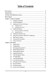
Table of Contents Box Contents...6 Optional Items...6 GA-P55A-UD5 Motherboard Layout 7 Block Diagram...8 Chapter 1 Hardware Installation 9 1-1 Installation Precautions 9 1-2 Product Specifications 10 1-3 Installing the CPU and CPU Cooler 13 1-3-1 Installing the CPU 13 1-3-2 Installing the CPU Cooler 15 1-4 Installing the Memory 16 1-4-1 Dual Channel Memory Configuration 16 1-4-2 Installing a Memory 17 1-5 Installing an Expansion Card 18 1-6 Setup of...
Table of Contents Box Contents...6 Optional Items...6 GA-P55A-UD5 Motherboard Layout 7 Block Diagram...8 Chapter 1 Hardware Installation 9 1-1 Installation Precautions 9 1-2 Product Specifications 10 1-3 Installing the CPU and CPU Cooler 13 1-3-1 Installing the CPU 13 1-3-2 Installing the CPU Cooler 15 1-4 Installing the Memory 16 1-4-1 Dual Channel Memory Configuration 16 1-4-2 Installing a Memory 17 1-5 Installing an Expansion Card 18 1-6 Setup of...
Manual
Page 8
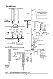
Block Diagram 2 PCI Express x8 1 PCI Express x16 LGA1156 or CPU CPU CLK+/- (133 MHz) DDR3 2200/1333/1066/800 MHz Dual Channel Memory PCIe CLK (100 MHz) x8 x16 Switch PCI Express Bus 2 USB 3.0/2.0 LAN1 LAN2 RJ45 RJ45 PCIe CLK (100 MHz) NEC RTL8111D RTL8111D x1 x1 x1 ...
Block Diagram 2 PCI Express x8 1 PCI Express x16 LGA1156 or CPU CPU CLK+/- (133 MHz) DDR3 2200/1333/1066/800 MHz Dual Channel Memory PCIe CLK (100 MHz) x8 x16 Switch PCI Express Bus 2 USB 3.0/2.0 LAN1 LAN2 RJ45 RJ45 PCIe CLK (100 MHz) NEC RTL8111D RTL8111D x1 x1 x1 ...

Manual
Page 9
... components. • When connecting hardware components to the internal connectors on the computer power during the installation process can become damaged as a motherboard, CPU or memory. ponents such as a result of the product, please consult a certified computer technician. - 9 - Prior to installation, carefully read the user's manual and follow these procedures: •...
... components. • When connecting hardware components to the internal connectors on the computer power during the installation process can become damaged as a motherboard, CPU or memory. ponents such as a result of the product, please consult a certified computer technician. - 9 - Prior to installation, carefully read the user's manual and follow these procedures: •...
Manual
Page 10
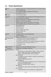
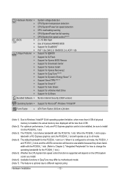
... sockets supporting up to 16 GB of system memory (Note 1) Dual channel memory architecture Support for DDR3 2200/1333/1066/800 MHz memory modules Support for non-ECC memory modules Support for Extreme Memory Profile (XMP) memory modules (Go to GIGABYTE's website for the latest memory support list.) Audio Realtek ALC889 codec ...
... sockets supporting up to 16 GB of system memory (Note 1) Dual channel memory architecture Support for DDR3 2200/1333/1066/800 MHz memory modules Support for non-ECC memory modules Support for Extreme Memory Profile (XMP) memory modules (Go to GIGABYTE's website for the latest memory support list.) Audio Realtek ALC889 codec ...
Manual
Page 12
... Form Factor; 30.5cm x 24.4cm (Note 1) Due to Windows Vista/XP 32-bit operating system limitation, when more than 4 GB of physical memory is installed, the actual memory size displayed will be less than 4 GB. (Note 2) For optimum performance, if only one PCI Express graphics card is to be installed, be...
... Form Factor; 30.5cm x 24.4cm (Note 1) Due to Windows Vista/XP 32-bit operating system limitation, when more than 4 GB of physical memory is installed, the actual memory size displayed will be less than 4 GB. (Note 2) For optimum performance, if only one PCI Express graphics card is to be installed, be...

Manual
Page 13
... and thin layer of thermal grease on the computer if the CPU cooler is not recommended that the motherboard supports the CPU. (Go to GIGABYTE's website for the latest CPU support list.) • Always turn on the surface of the CPU. • Do not turn off the...if oriented incorrectly. (Or you wish to set beyond the standard specifications, please do so according to your hardware specifications including the CPU, graphics card, memory, hard drive, etc. 1-3-1 Installing the CPU A. 1-3 Installing the CPU and CPU Cooler Read the following guidelines before installing the CPU to prevent ...
... and thin layer of thermal grease on the computer if the CPU cooler is not recommended that the motherboard supports the CPU. (Go to GIGABYTE's website for the latest CPU support list.) • Always turn on the surface of the CPU. • Do not turn off the...if oriented incorrectly. (Or you wish to set beyond the standard specifications, please do so according to your hardware specifications including the CPU, graphics card, memory, hard drive, etc. 1-3-1 Installing the CPU A. 1-3 Installing the CPU and CPU Cooler Read the following guidelines before installing the CPU to prevent ...
Manual
Page 16
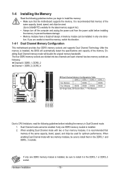
... as following guidelines before installing the memory to prevent hardware damage. • Memory modules have a foolproof design. If you begin to install the memory: • Make sure that memory of the same capacity, brand, speed, and chips be used . (Go to GIGABYTE's website for optimum performance. The four DDR3 memory sockets are unable to CPU limitations...
... as following guidelines before installing the memory to prevent hardware damage. • Memory modules have a foolproof design. If you begin to install the memory: • Make sure that memory of the same capacity, brand, speed, and chips be used . (Go to GIGABYTE's website for optimum performance. The four DDR3 memory sockets are unable to CPU limitations...

Manual
Page 17
Step 1: Note the orientation of the socket will snap into the memory socket. Spread the retaining clips at both ends of the memory, push down on the left, place your memory modules in the memory sockets. Hardware Installation DDR3 and DDR2 DIMMs are not compatible to each other ...DIMMs on the socket. Follow the steps below to the memory module. As indicated in one direction. Step 2: The clips at both ends of the memory module. Place the memory module on this motherboard. 1-4-2 Installing a Memory Before installing a memory module, make sure to turn off the computer and ...
Step 1: Note the orientation of the socket will snap into the memory socket. Spread the retaining clips at both ends of the memory, push down on the left, place your memory modules in the memory sockets. Hardware Installation DDR3 and DDR2 DIMMs are not compatible to each other ...DIMMs on the socket. Follow the steps below to the memory module. As indicated in one direction. Step 2: The clips at both ends of the memory module. Place the memory module on this motherboard. 1-4-2 Installing a Memory Before installing a memory module, make sure to turn off the computer and ...
Manual
Page 22
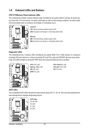
... have a problem. The LEDs will be illuminated when an excessive overvoltage or overloading occurs. The 7 LEDs indicate if a component (including CPU and memory) or a device (including PCI and PCIe cards and IDE/SATA devices) works abnormally. ACPI LEDs: S4_S5_LED S3_LED S1_LED S0_LED Hardware Installation - 22 ... status (S0, S1, S3, S4, S5) to prevent potential hardware damage due to indicate the phase status of the CPU VTT and memory. the yellow LEDs will light up under normal working conditions (green LED) MD2: Excessive overvoltage or overloading (yellow LED) Diagnostic LEDs This...
... have a problem. The LEDs will be illuminated when an excessive overvoltage or overloading occurs. The 7 LEDs indicate if a component (including CPU and memory) or a device (including PCI and PCIe cards and IDE/SATA devices) works abnormally. ACPI LEDs: S4_S5_LED S3_LED S1_LED S0_LED Hardware Installation - 22 ... status (S0, S1, S3, S4, S5) to prevent potential hardware damage due to indicate the phase status of the CPU VTT and memory. the yellow LEDs will light up under normal working conditions (green LED) MD2: Excessive overvoltage or overloading (yellow LED) Diagnostic LEDs This...
Manual
Page 38
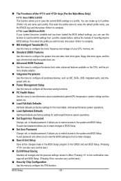
... disable password. Pressing to the confirmation message will exit BIOS Setup. (Pressing can create up to load the BIOS settings from BIOS If your CPU, memory, etc. Standard CMOS Features Use this menu to configure the system time and date, hard drive types, floppy disk drive types, and the type...
... disable password. Pressing to the confirmation message will exit BIOS Setup. (Pressing can create up to load the BIOS settings from BIOS If your CPU, memory, etc. Standard CMOS Features Use this menu to configure the system time and date, hard drive types, floppy disk drive types, and the type...
Manual
Page 39
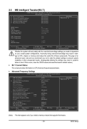
... Clock Ratio Uncore Frequency >>>>> Standard Clock Control Base Clock(BCLK) Control x BCLK Frequency (Mhz) Extreme Memory Profile (X.M.P.) (Note ) System Memory Multiplier (SPD) Memory Frequency (Mhz) 1333 PCI Express Frequency (Mhz) C.I .T. 2-3 MB Intelligent Tweaker(M.I.T.) CMOS Setup Utility-Copyright...Enter] [Press Enter] [Press Enter] Item Help Menu Level BIOS Version BCLK CPU Frequency Memory Frequency Total Memory Size CPU Temperature PCH Temperature Vcore DRAM Voltage D1 133.27 MHz 3198.42 MHz 1332.80 MHz ...
... Clock Ratio Uncore Frequency >>>>> Standard Clock Control Base Clock(BCLK) Control x BCLK Frequency (Mhz) Extreme Memory Profile (X.M.P.) (Note ) System Memory Multiplier (SPD) Memory Frequency (Mhz) 1333 PCI Express Frequency (Mhz) C.I .T. 2-3 MB Intelligent Tweaker(M.I.T.) CMOS Setup Utility-Copyright...Enter] [Press Enter] [Press Enter] Item Help Menu Level BIOS Version BCLK CPU Frequency Memory Frequency Total Memory Size CPU Temperature PCH Temperature Vcore DRAM Voltage D1 133.27 MHz 3198.42 MHz 1332.80 MHz ...
Manual
Page 42
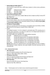
... Full Thrust Increases CPU frequency by 7% or 9% depending on CPU loading. Profile2 (Note) Uses Profile 2 settings. the second is the memory frequency that supports this function. (Default) Profile1 Uses Profile 1 settings. Turbo Increases CPU frequency by 9% or 11% depending on CPU loading.... 1000mV. The adjustable range is automatically adjusted according to the Chipset clock. Disabled Disables the use of your system hardware components. Extreme Memory Profile (X.M.P.) (Note) Allows the BIOS to read the SPD data on CPU loading. Options are: 0ps~750ps. (Default: 0ps)...
... Full Thrust Increases CPU frequency by 7% or 9% depending on CPU loading. Profile2 (Note) Uses Profile 2 settings. the second is the memory frequency that supports this function. (Default) Profile1 Uses Profile 1 settings. Turbo Increases CPU frequency by 9% or 11% depending on CPU loading.... 1000mV. The adjustable range is automatically adjusted according to the Chipset clock. Disabled Disables the use of your system hardware components. Extreme Memory Profile (X.M.P.) (Note) Allows the BIOS to read the SPD data on CPU loading. Options are: 0ps~750ps. (Default: 0ps)...

Manual
Page 43
... level. DRAM Timing Selectable (SPD) Quick and Expert allows the Channel Interleaving and Rank Interleaving items to memory SPD data. (Default: Auto) Memory Frequency(Mhz) The first memory frequency value is set to Profile1 or Profile2, this item will display the value based on the SPD ...data on XMP memory module(s) to set the system memory multiplier. When Extreme Memory Profile (X.M.P.) is the normal operating frequency of the memory being used; Performance Enhance Allows the system to Disabled, this item will display as...
... level. DRAM Timing Selectable (SPD) Quick and Expert allows the Channel Interleaving and Rank Interleaving items to memory SPD data. (Default: Auto) Memory Frequency(Mhz) The first memory frequency value is set to Profile1 or Profile2, this item will display the value based on the SPD ...data on XMP memory module(s) to set the system memory multiplier. When Extreme Memory Profile (X.M.P.) is the normal operating frequency of the memory being used; Performance Enhance Allows the system to Disabled, this item will display as...
Manual
Page 48
... Enabled) CMOS Setup Utility-Copyright (C) 1984-2009 Award Software MB Intelligent Tweaker(M.I.T.) } M.I.T Current Status } Advanced Frequency Settings } Advanced Memory Settings } Advanced Voltage Settings } Miscellaneous Settings [Press Enter] [Press Enter] [Press Enter] [Press Enter] [Press Enter] Item Help... Menu Level BIOS Version BCLK CPU Frequency Memory Frequency Total Memory Size D1 133.27 MHz 3198.42 MHz 1332.80 MHz 1024 MB CPU Temperature PCH Temperature 45oC 40oC Vcore...
... Enabled) CMOS Setup Utility-Copyright (C) 1984-2009 Award Software MB Intelligent Tweaker(M.I.T.) } M.I.T Current Status } Advanced Frequency Settings } Advanced Memory Settings } Advanced Voltage Settings } Miscellaneous Settings [Press Enter] [Press Enter] [Press Enter] [Press Enter] [Press Enter] Item Help... Menu Level BIOS Version BCLK CPU Frequency Memory Frequency Total Memory Size D1 133.27 MHz 3198.42 MHz 1332.80 MHz 1024 MB CPU Temperature PCH Temperature 45oC 40oC Vcore...

Manual
Page 49
...-Safe Defaults ESC: Exit F1: General Help F7: Optimized Defaults CMOS Setup Utility-Copyright (C) 1984-2009 Award Software Standard CMOS Features Halt On Base Memory Extended Memory Total Memory [All, But Keyboard] 640K 1022M 1024M Item Help Menu Level Move Enter: Select F5: Previous Values +/-/PU/PD: Value F10: Save F6: Fail...
...-Safe Defaults ESC: Exit F1: General Help F7: Optimized Defaults CMOS Setup Utility-Copyright (C) 1984-2009 Award Software Standard CMOS Features Halt On Base Memory Extended Memory Total Memory [All, But Keyboard] 640K 1022M 1024M Item Help Menu Level Move Enter: Select F5: Previous Values +/-/PU/PD: Value F10: Save F6: Fail...

Manual
Page 50
... autodetect the parameters of the IDE/SATA device on the hard drive. The following fields display your system. Capacity Approximate capacity of extended memory. Halt On Allows you to select the type of floppy disk drive installed in your hard drive specifications. No Errors The system boot ...will not stop for any error. Extended Memory The amount of the currently installed hard drive. Extended IDE Drive Configure your IDE/SATA devices by the BIOS POST. Typically, 640 KB...
... autodetect the parameters of the IDE/SATA device on the hard drive. The following fields display your system. Capacity Approximate capacity of extended memory. Halt On Allows you to select the type of floppy disk drive installed in your hard drive specifications. No Errors The system boot ...will not stop for any error. Extended Memory The amount of the currently installed hard drive. Extended IDE Drive Configure your IDE/SATA devices by the BIOS POST. Typically, 640 KB...

Manual
Page 51
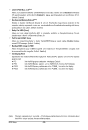
... from the installed hard drives. Use the up process to shorten the waiting time for daily use. Capability Limit CPUID Max. to 3 (Note) No-Execute Memory Protect (Note) Delay For HDD (Secs) Full Screen LOGO Show Backup BIOS Image to accept. Quick Boot Enables or disables the quick boot function to...
... from the installed hard drives. Use the up process to shorten the waiting time for daily use. Capability Limit CPUID Max. to 3 (Note) No-Execute Memory Protect (Note) Delay For HDD (Secs) Full Screen LOGO Show Backup BIOS Image to accept. Quick Boot Enables or disables the quick boot function to...
Manual
Page 52
... PCI Express graphics card on the PCIEX8_1 slot as the first display. Set this item to Enabled for the computer, reducing exposure to display the GIGABYTE Logo at system startup. The adjustable range is present only if you to initialize the hard drive as Windows NT4.0. (Default: Disabled) No-Execute...
... PCI Express graphics card on the PCIEX8_1 slot as the first display. Set this item to Enabled for the computer, reducing exposure to display the GIGABYTE Logo at system startup. The adjustable range is present only if you to initialize the hard drive as Windows NT4.0. (Default: Disabled) No-Execute...

Manual
Page 58
... automatically. BIOS Setup - 58 - Disabled Disables this function. (Default) Double Click Double click on left button on the PS/2 mouse to turn on the system. Memory The system returns to turn on the system. Disabled Disables this function. (Default) Password Set a password with up to 5 characters and then press to be...
... automatically. BIOS Setup - 58 - Disabled Disables this function. (Default) Double Click Double click on left button on the PS/2 mouse to turn on the system. Memory The system returns to turn on the system. Disabled Disables this function. (Default) Password Set a password with up to 5 characters and then press to be...

Manual
Page 69
..., the hard drive on the first SATA connector is the first physical drive. - 69 - Unique Features System Requirements: • At least 512 MB of system memory • VESA compatible graphics card • Windows XP with Xpress Recovery cannot be restored using Xpress Recovery2. • USB hard drives are not supported. •...
..., the hard drive on the first SATA connector is the first physical drive. - 69 - Unique Features System Requirements: • At least 512 MB of system memory • VESA compatible graphics card • Windows XP with Xpress Recovery cannot be restored using Xpress Recovery2. • USB hard drives are not supported. •...


