
Manual
Page 1
GA-P55-USB3L LGA1156 socket motherboard for Intel® Core™ i7 processor family/ Intel® Core™ i5 processor family/Intel® Core™ i3 processor family User's Manual Rev. 1001 12ME-P55SB3L-1001R
GA-P55-USB3L LGA1156 socket motherboard for Intel® Core™ i7 processor family/ Intel® Core™ i5 processor family/Intel® Core™ i3 processor family User's Manual Rev. 1001 12ME-P55SB3L-1001R
Manual
Page 2
Motherboard GA-P55-USB3L Dec. 24, 2009 Motherboard GA-P55-USB3L Dec. 24, 2009
Motherboard GA-P55-USB3L Dec. 24, 2009 Motherboard GA-P55-USB3L Dec. 24, 2009

Manual
Page 4
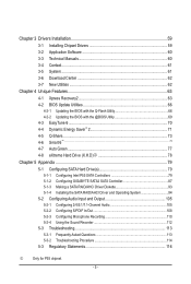
Table of Contents Box Contents...6 Optional Items...6 GA-P55-USB3L Motherboard Layout 7 GA-P55-USB3L Motherboard Block Diagram 8 Chapter 1 Hardware Installation 9 1-1 Installation Precautions 9 1-2 Product Specifications 10 1-3 Installing the CPU and CPU Cooler 13 1-3-1 Installing the CPU 13 1-3-2 Installing the CPU ...
Table of Contents Box Contents...6 Optional Items...6 GA-P55-USB3L Motherboard Layout 7 GA-P55-USB3L Motherboard Block Diagram 8 Chapter 1 Hardware Installation 9 1-1 Installation Precautions 9 1-2 Product Specifications 10 1-3 Installing the CPU and CPU Cooler 13 1-3-1 Installing the CPU 13 1-3-2 Installing the CPU ...
Manual
Page 5
...4-6 Smart 6™...74 4-7 Auto Green...77 4-8 eXtreme Hard Drive (X.H.D)j 78 Chapter 5 Appendix...79 5-1 Configuring SATA Hard Drive(s 79 5-1-1 Configuring Intel P55 SATA Controllers 79 5-1-2 Configuring GIGABYTE SATA2 SATA Controller 87 5-1-3 Making a SATA RAID/AHCI Driver Diskette 93 5-1-4 Installing the SATA RAID/AHCI Driver and Operating System 94 5-2 Configuring Audio... 5-2-4 Using the Sound Recorder 112 5-3 Troubleshooting 113 5-3-1 Frequently Asked Questions 113 5-3-2 Troubleshooting Procedure 114 5-3 Regulatory Statements 116 j Only for P55 chipset. - 5 -
...4-6 Smart 6™...74 4-7 Auto Green...77 4-8 eXtreme Hard Drive (X.H.D)j 78 Chapter 5 Appendix...79 5-1 Configuring SATA Hard Drive(s 79 5-1-1 Configuring Intel P55 SATA Controllers 79 5-1-2 Configuring GIGABYTE SATA2 SATA Controller 87 5-1-3 Making a SATA RAID/AHCI Driver Diskette 93 5-1-4 Installing the SATA RAID/AHCI Driver and Operating System 94 5-2 Configuring Audio... 5-2-4 Using the Sound Recorder 112 5-3 Troubleshooting 113 5-3-1 Frequently Asked Questions 113 5-3-2 Troubleshooting Procedure 114 5-3 Regulatory Statements 116 j Only for P55 chipset. - 5 -
Manual
Page 6
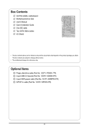
...-1FD001-7*R) 2-port USB 2.0 bracket (Part No. 12CR1-1UB030-5*R) 2-port SATA power cable (Part No. 12CF1-2SERPW-0*R) S/PDIF In cable (Part No. 12CR1-1SPDIN-0*R) - 6 - Box Contents GA-P55-USB3L motherboard Motherboard driver disk User's Manual Quick Installation Guide One IDE cable Two SATA 3Gb/s cables I/O Shield • The box contents above are subject to...
...-1FD001-7*R) 2-port USB 2.0 bracket (Part No. 12CR1-1UB030-5*R) 2-port SATA power cable (Part No. 12CF1-2SERPW-0*R) S/PDIF In cable (Part No. 12CR1-1SPDIN-0*R) - 6 - Box Contents GA-P55-USB3L motherboard Motherboard driver disk User's Manual Quick Installation Guide One IDE cable Two SATA 3Gb/s cables I/O Shield • The box contents above are subject to...

Manual
Page 7
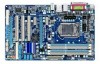
... card, use other expansion slots. - 7 - GA-P55-USB3L Motherboard Layout COAXIAL COMA LPT KB_USB ATX_12V GA-P55-USB3L PHASE LED LGA1156 PWR_FAN R_USB ATX USB30_LAN AUDIO F_AUDIO ...NEC D720200F1 SYS_FAN1 PCIEX1_1 (Note) CPU_FAN DDR3_2 DDR3_1 DDR3_4 DDR3_3 RTL8111D CODEC SPDIF_O CD_IN SPDIF_I PCIEX16 PCIEX1_2 PCI1 PCI2 PCI3 SYS_FAN2 BAT Intel® P55/H55 SATA2_0 SATA2_1 SATA2_2 SATA2_5 SATA2_4SATA2_3 IDE IT8720 B_BIOS M_BIOS FDD PCIEX4_X1 F_USB3j F_USB1 F_USB2 GSATA2_6 CLR_CMOS GIGABYTE...
... card, use other expansion slots. - 7 - GA-P55-USB3L Motherboard Layout COAXIAL COMA LPT KB_USB ATX_12V GA-P55-USB3L PHASE LED LGA1156 PWR_FAN R_USB ATX USB30_LAN AUDIO F_AUDIO ...NEC D720200F1 SYS_FAN1 PCIEX1_1 (Note) CPU_FAN DDR3_2 DDR3_1 DDR3_4 DDR3_3 RTL8111D CODEC SPDIF_O CD_IN SPDIF_I PCIEX16 PCIEX1_2 PCI1 PCI2 PCI3 SYS_FAN2 BAT Intel® P55/H55 SATA2_0 SATA2_1 SATA2_2 SATA2_5 SATA2_4SATA2_3 IDE IT8720 B_BIOS M_BIOS FDD PCIEX4_X1 F_USB3j F_USB1 F_USB2 GSATA2_6 CLR_CMOS GIGABYTE...
Manual
Page 8
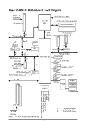
j Only for H55 chipset. k Only for P55 chipset. GA-P55-USB3L Motherboard Block Diagram PCIe CLK (100 MHz) 1 PCI Express x16 LGA1156 CPU CPU CLK+/- (133 MHz) DDR3 2200/1333/1066/800 MHz Dual Channel Memory ...) 2 SATA 3Gb/s ATA-133/100/66/33 IDE Channel PCI Bus 2 USB 3.0 NEC D720200F1 Intel® P55/H55 x4j/X1k x1 Switchj PCI Express Bus Dual BIOS 6 SATA 3Gb/s x1 14 USB 2.0/1.1j (Note) GIGABYTE SATA2 12 USB 2.0/1.1k (Note) CODEC LPC Bus IT8720 Floppy COM Port PS/2 KB/Mouse MIC (Center...
j Only for H55 chipset. k Only for P55 chipset. GA-P55-USB3L Motherboard Block Diagram PCIe CLK (100 MHz) 1 PCI Express x16 LGA1156 CPU CPU CLK+/- (133 MHz) DDR3 2200/1333/1066/800 MHz Dual Channel Memory ...) 2 SATA 3Gb/s ATA-133/100/66/33 IDE Channel PCI Bus 2 USB 3.0 NEC D720200F1 Intel® P55/H55 x4j/X1k x1 Switchj PCI Express Bus Dual BIOS 6 SATA 3Gb/s x1 14 USB 2.0/1.1j (Note) GIGABYTE SATA2 12 USB 2.0/1.1k (Note) CODEC LPC Bus IT8720 Floppy COM Port PS/2 KB/Mouse MIC (Center...
Manual
Page 10
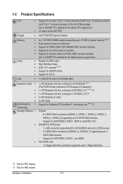
...™ i5 series processor /Intel® Core™ i3 series processor in the LGA1156 package (Go to GIGABYTE's website for the latest CPU support list.) L3 cache varies with CPU Chipset Intel® P55/H55 Express Chipset Memory Audio 4 x 1.5V DDR3 DIMM sockets supporting up to 16 GB of system...
...™ i5 series processor /Intel® Core™ i3 series processor in the LGA1156 package (Go to GIGABYTE's website for the latest CPU support list.) L3 cache varies with CPU Chipset Intel® P55/H55 Express Chipset Memory Audio 4 x 1.5V DDR3 DIMM sockets supporting up to 16 GB of system...

Manual
Page 11
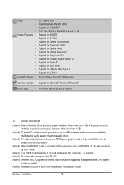
k Only for P55 chipset. Up to the internal USB headers) k NEC D720200F1 chip: - Up to 12 USB 2.0/1.1 ports (Note 6) (8 on the back panel Internal w 1 x 24-pin ATX ...
k Only for P55 chipset. Up to the internal USB headers) k NEC D720200F1 chip: - Up to 12 USB 2.0/1.1 ports (Note 6) (8 on the back panel Internal w 1 x 24-pin ATX ...
Manual
Page 12
... Internet Security (OEM version) Operating System w Support for Microsoft® Windows® 7/Vista/XP Form Factor w ATX Form Factor; 30.5cm x 19.0cm j Only for P55 chipset. (Note 1) Due to Windows 32-bit operating system limitation, when more than 4 GB of physical memory is installed, the actual memory size displayed will...
... Internet Security (OEM version) Operating System w Support for Microsoft® Windows® 7/Vista/XP Form Factor w ATX Form Factor; 30.5cm x 19.0cm j Only for P55 chipset. (Note 1) Due to Windows 32-bit operating system limitation, when more than 4 GB of physical memory is installed, the actual memory size displayed will...

Manual
Page 21
.../7 5 2 4 8 8 7 11 6 16 9 17 10) BAT 11) F_PANEL 12) F_AUDIO 13) CD_IN 14) SPDIF_I 15) SPDIF_O 16) F_USB1/F_USB2/(F_USB3j) 17) CLR_CMOS 18) PHASE_LED j Only for P55 chipset. Read the following guidelines before turning on the computer, make sure your computer.
.../7 5 2 4 8 8 7 11 6 16 9 17 10) BAT 11) F_PANEL 12) F_AUDIO 13) CD_IN 14) SPDIF_I 15) SPDIF_O 16) F_USB1/F_USB2/(F_USB3j) 17) CLR_CMOS 18) PHASE_LED j Only for P55 chipset. Read the following guidelines before turning on the computer, make sure your computer.
Manual
Page 24
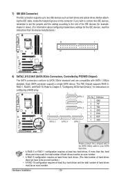
... devices, read the instructions from the device manufacturers.) 39 1 40 2 8) SATA2_0/1/2/3/4/5 (SATA 3Gb/s Connectors, Controlled by P55/H55 Chipset) The SATA connectors conform to two IDE devices such as hard drives and optical drives. The P55 Chipset supports RAID 0, RAID 1, RAID 5, and RAID 10. Each SATA connector supports a single SATA device. Hardware...
... devices, read the instructions from the device manufacturers.) 39 1 40 2 8) SATA2_0/1/2/3/4/5 (SATA 3Gb/s Connectors, Controlled by P55/H55 Chipset) The SATA connectors conform to two IDE devices such as hard drives and optical drives. The P55 Chipset supports RAID 0, RAID 1, RAID 5, and RAID 10. Each SATA connector supports a single SATA device. Hardware...

Manual
Page 29
... values and before turning on the two pins to temporarily short the two pins or use a metal object like a screwdriver to USB 2.0/1.1 specification. j Only for P55 chipset. - 29 - Open: Normal Short: Clear CMOS Values • Always turn off your computer and unplug the power cord from the jumper. Failure to do...
... values and before turning on the two pins to temporarily short the two pins or use a metal object like a screwdriver to USB 2.0/1.1 specification. j Only for P55 chipset. - 29 - Open: Normal Short: Clear CMOS Values • Always turn off your computer and unplug the power cord from the jumper. Failure to do...
Manual
Page 32
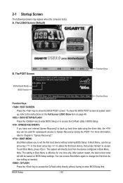
... or to access the Q-Flash utility in Boot Menu. The LOGO Screen (Default) B. BIOS Setup - 32 - Motherboard Model BIOS Version P55-USB3L E12c . . . . : BIOS Setup : XpressRecovery2 : Boot Menu : Qflash 12/04/2009-P55-7A89TG0DC-00 Function Keys Function Keys Function Keys: : POST SCREEN Press the key to enter BIOS Setup first. After system...
... or to access the Q-Flash utility in Boot Menu. The LOGO Screen (Default) B. BIOS Setup - 32 - Motherboard Model BIOS Version P55-USB3L E12c . . . . : BIOS Setup : XpressRecovery2 : Boot Menu : Qflash 12/04/2009-P55-7A89TG0DC-00 Function Keys Function Keys Function Keys: : POST SCREEN Press the key to enter BIOS Setup first. After system...
Manual
Page 49
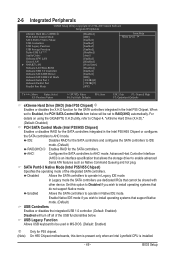
... CPU is an interface specification that allows the storage driver to operate in the Intel P55 Chipset. SATA Port0-3 Native Mode (Intel P55/H55 Chipset) Specifies the operating mode of the USB functionalities below. BIOS Setup Enabled...P55 chipset. (Note) On H55 Chipset motherboards, this option to Disabled if you wish to install operating systems that support Native mode. (Default) USB Controllers Enables or disables the integrated USB 1.0 controller. (Default: Enabled) Disabled will be shared with other device. For details on using the GIGABYTE...
... CPU is an interface specification that allows the storage driver to operate in the Intel P55 Chipset. SATA Port0-3 Native Mode (Intel P55/H55 Chipset) Specifies the operating mode of the USB functionalities below. BIOS Setup Enabled...P55 chipset. (Note) On H55 Chipset motherboards, this option to Disabled if you wish to install operating systems that support Native mode. (Default) USB Controllers Enables or disables the integrated USB 1.0 controller. (Default: Enabled) Disabled will be shared with other device. For details on using the GIGABYTE...

Manual
Page 66
...independent IDE/SATA controller, use FAT32/16/12 file system. 3. However, if the main BIOS is saved to access Q-Flash. From GIGABYTE's website, download the latest compressed BIOS update file that support DualBIOS have two BIOS onboard, a main BIOS and a backup BIOS. p55usb3l... will take over on the main BIOS. 4-2 BIOS Update Utilities GIGABYTE motherboards provide two unique BIOS update tools, Q-Flash™ and @BIOS™. P55-USB3L E12c . . . . : BIOS Setup : XpressRecovery2 : Boot Menu : Qflash 12/04/2009-P55-7A89TG0DC-00 Because BIOS flashing is @BIOS™? @BIOS allows you...
...independent IDE/SATA controller, use FAT32/16/12 file system. 3. However, if the main BIOS is saved to access Q-Flash. From GIGABYTE's website, download the latest compressed BIOS update file that support DualBIOS have two BIOS onboard, a main BIOS and a backup BIOS. p55usb3l... will take over on the main BIOS. 4-2 BIOS Update Utilities GIGABYTE motherboards provide two unique BIOS update tools, Q-Flash™ and @BIOS™. P55-USB3L E12c . . . . : BIOS Setup : XpressRecovery2 : Boot Menu : Qflash 12/04/2009-P55-7A89TG0DC-00 Because BIOS flashing is @BIOS™? @BIOS allows you...

Manual
Page 78
...into the array to exit the X.H.D utility. (Note 1) The X.H.D utility only supports the SATA controllers integrated in the array. ) 1. Using GIGABYTE eXtreme Hard Drive (X.H.D) Instructions:(Note 2) Before launching X.H.D, make sure the new drive is greater than or equal to the biggest drive in the Intel... RAID 0 when a new SATA drive is recommended that already exists, users also can click the Xpress Install All button to enable RAID for P55 chipset. Unique Features - 78 - For a RAID 0 array that before you run the X.H.D utility, back up all motherboard drivers, including the...
...into the array to exit the X.H.D utility. (Note 1) The X.H.D utility only supports the SATA controllers integrated in the array. ) 1. Using GIGABYTE eXtreme Hard Drive (X.H.D) Instructions:(Note 2) Before launching X.H.D, make sure the new drive is greater than or equal to the biggest drive in the Intel... RAID 0 when a new SATA drive is recommended that already exists, users also can click the Xpress Install All button to enable RAID for P55 chipset. Unique Features - 78 - For a RAID 0 array that before you run the X.H.D utility, back up all motherboard drivers, including the...
Manual
Page 79
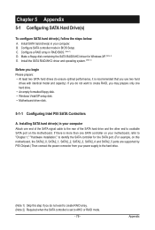
... controller is more than one SATA controller on this motherboard, the SATA2_0, SATA2_1, SATA2_2, SATA2_3, SATA2_4 and SATA2_5 ports are supported by P55 Chipset.) Then connect the power connector from your computer. If you use two hard drives with identical model and capacity). Make a floppy... drive. • An empty formatted floppy disk. • Windows Vista/XP setup disk. • Motherboard driver disk. 5-1-1 Configuring Intel P55 SATA Controllers A. Appendix B. C. Chapter 5 Appendix 5-1 Configuring SATA Hard Drive(s) To configure SATA hard drive(s), follow the steps below: A.
... controller is more than one SATA controller on this motherboard, the SATA2_0, SATA2_1, SATA2_2, SATA2_3, SATA2_4 and SATA2_5 ports are supported by P55 Chipset.) Then connect the power connector from your computer. If you use two hard drives with identical model and capacity). Make a floppy... drive. • An empty formatted floppy disk. • Windows Vista/XP setup disk. • Motherboard driver disk. 5-1-1 Configuring Intel P55 SATA Controllers A. Appendix B. C. Chapter 5 Appendix 5-1 Configuring SATA Hard Drive(s) To configure SATA hard drive(s), follow the steps below: A.

Manual
Page 81
Skip this step and proceed with the installation of Windows operating system for a message which says "Press to enter the P55 RAID Configuration Utility. option ROM - 9.5.0.1037 Copyright(C) 2003-09 Intel Corporation. Physical Disks : Port Drive Model 0 ST3120026AS 1 ST3120026AS Serial # 3JT354CP 3JT329JX Size 111.7GB 111....
Skip this step and proceed with the installation of Windows operating system for a message which says "Press to enter the P55 RAID Configuration Utility. option ROM - 9.5.0.1037 Copyright(C) 2003-09 Intel Corporation. Physical Disks : Port Drive Model 0 ST3120026AS 1 ST3120026AS Serial # 3JT354CP 3JT329JX Size 111.7GB 111....
Manual
Page 93
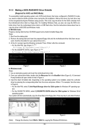
... Prompt window will then automatically copy the driver files to a floppy disk. Press after the command: • For the Intel P55, type (Figure 1): (Note) A:\>copy d:\bootdrv\irst\32bit\*.* • For the GIGABYTE SATA2, type (Figure 2): (Note) A:\>copy d:\bootdrv\gsata\32bit\*.* Figure 1 Figure 2 In Windows mode: Steps: 1: Use an alternative system and insert...
... Prompt window will then automatically copy the driver files to a floppy disk. Press after the command: • For the Intel P55, type (Figure 1): (Note) A:\>copy d:\bootdrv\irst\32bit\*.* • For the GIGABYTE SATA2, type (Figure 2): (Note) A:\>copy d:\bootdrv\gsata\32bit\*.* Figure 1 Figure 2 In Windows mode: Steps: 1: Use an alternative system and insert...