
Manual
Page 1
...Hard Drive (X.H.D) under the Integrated Peripherals menu to Enabled to load the SATA controller driver first. eXtreme Hard Drive (X.H.D) With GIGABYTE eXtreme Hard Drive (X.H.D)(Note 1), users can click the Xpress Install All button to enhance your hard drive read/write performance without ... equal to Chapter 5, "Installing the SATA RAID/AHCI Driver and Operating System." ) Step 3: Install the motherboard drivers and the X.H.D utiltiy After installing the operating system, insert the motherboard driver disk. To manually set up a RAID array: (Note 3): Click Manual to set up a RAID...
...Hard Drive (X.H.D) under the Integrated Peripherals menu to Enabled to load the SATA controller driver first. eXtreme Hard Drive (X.H.D) With GIGABYTE eXtreme Hard Drive (X.H.D)(Note 1), users can click the Xpress Install All button to enhance your hard drive read/write performance without ... equal to Chapter 5, "Installing the SATA RAID/AHCI Driver and Operating System." ) Step 3: Install the motherboard drivers and the X.H.D utiltiy After installing the operating system, insert the motherboard driver disk. To manually set up a RAID array: (Note 3): Click Manual to set up a RAID...
Manual
Page 1
GA-P55-USB3 LGA1156 socket motherboard for Intel® Core™ i7 processor family/ Intel® Core™ i5 processor family User's Manual Rev. 1001 12ME-P55USB3-1001R
GA-P55-USB3 LGA1156 socket motherboard for Intel® Core™ i7 processor family/ Intel® Core™ i5 processor family User's Manual Rev. 1001 12ME-P55USB3-1001R

Manual
Page 2
Motherboard GA-P55-USB3 Dec. 24, 2009 Motherboard GA-P55-USB3 Dec. 24, 2009
Motherboard GA-P55-USB3 Dec. 24, 2009 Motherboard GA-P55-USB3 Dec. 24, 2009
Manual
Page 3
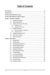
...GIGA-BYTE TECHNOLOGY CO., LTD. All rights reserved. For product-related information, check on our website at: http://www.gigabyte.com.tw Identifying Your Motherboard Revision The revision number on our website. For example, "REV: 1.0" means the revision of this manual are legally ...to assist in this : "REV: X.X." Check your motherboard looks like this manual may be reproduced, copied, translated, transmitted, or published in this manual may be made by any form or by GIGABYTE without GIGABYTE's prior written permission. Documentation Classifications In order to the ...
...GIGA-BYTE TECHNOLOGY CO., LTD. All rights reserved. For product-related information, check on our website at: http://www.gigabyte.com.tw Identifying Your Motherboard Revision The revision number on our website. For example, "REV: 1.0" means the revision of this manual are legally ...to assist in this : "REV: X.X." Check your motherboard looks like this manual may be reproduced, copied, translated, transmitted, or published in this manual may be made by any form or by GIGABYTE without GIGABYTE's prior written permission. Documentation Classifications In order to the ...
Manual
Page 4
Table of Contents Box Contents...6 Optional Items...6 GA-P55-USB3 Motherboard Layout 7 GA-P55-USB3 Motherboard Block Diagram 8 Chapter 1 Hardware Installation 9 1-1 Installation Precautions 9 1-2 Product Specifications 10 1-3 Installing the CPU and CPU Cooler 13 1-3-1 Installing the CPU 13 1-3-2 Installing the CPU Cooler ...
Table of Contents Box Contents...6 Optional Items...6 GA-P55-USB3 Motherboard Layout 7 GA-P55-USB3 Motherboard Block Diagram 8 Chapter 1 Hardware Installation 9 1-1 Installation Precautions 9 1-2 Product Specifications 10 1-3 Installing the CPU and CPU Cooler 13 1-3-1 Installing the CPU 13 1-3-2 Installing the CPU Cooler ...
Manual
Page 6
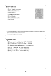
...(Part No. 12CR1-1SPDIN-0*R) COM port cable (Part No. 12CF1-1CM001-3*R) LPT port cable (Part No. 12CF1-1LP001-0*R) - 6 - Box Contents GA-P55-USB3 motherboard Motherboard driver disk User's Manual Quick Installation Guide One IDE cable Two SATA 3Gb/s cables I/O Shield • The box contents above are subject to change ...without notice. • The motherboard image is for reference only and the actual items shall depend on the product package you obtain. The box contents are for reference only...
...(Part No. 12CR1-1SPDIN-0*R) COM port cable (Part No. 12CF1-1CM001-3*R) LPT port cable (Part No. 12CF1-1LP001-0*R) - 6 - Box Contents GA-P55-USB3 motherboard Motherboard driver disk User's Manual Quick Installation Guide One IDE cable Two SATA 3Gb/s cables I/O Shield • The box contents above are subject to change ...without notice. • The motherboard image is for reference only and the actual items shall depend on the product package you obtain. The box contents are for reference only...

Manual
Page 7
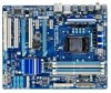
GA-P55-USB3 Motherboard Layout KB_USBj R_SPDIF CPU_FAN ATX_12V_2X4 R_USB_2 R_USB_1 R_USB30 LGA1156 PWR_FAN PHASE LED ATX USB_LAN NEC AUDIO F_AUDIO RTL8111D PCIEX16 GA-P55-USB3 PCIEX1_1 (Note) SYS_FAN1 IDE SYS_FAN2 DDR3_2 DDR3_1 DDR3_4 DDR3_3 PCIEX1_2 BAT CODEC PCI1 PCIEX4_X1 GIGABYTE SATA2 Intel® P55/H55 GSATA2_6 GSATA2_7 CD_IN SPDIF_I SPDIF_O IT8720 PCI2 PCI3 LPT COMA B_BIOS FDD F_USB2 M_BIOS...
GA-P55-USB3 Motherboard Layout KB_USBj R_SPDIF CPU_FAN ATX_12V_2X4 R_USB_2 R_USB_1 R_USB30 LGA1156 PWR_FAN PHASE LED ATX USB_LAN NEC AUDIO F_AUDIO RTL8111D PCIEX16 GA-P55-USB3 PCIEX1_1 (Note) SYS_FAN1 IDE SYS_FAN2 DDR3_2 DDR3_1 DDR3_4 DDR3_3 PCIEX1_2 BAT CODEC PCI1 PCIEX4_X1 GIGABYTE SATA2 Intel® P55/H55 GSATA2_6 GSATA2_7 CD_IN SPDIF_I SPDIF_O IT8720 PCI2 PCI3 LPT COMA B_BIOS FDD F_USB2 M_BIOS...

Manual
Page 8
GA-P55-USB3 Motherboard Block Diagram PCIe CLK (100 MHz) 1 PCI Express x16 LGA1156 CPU CPU CLK+/- (133 MHz) DDR3 2200/1333/1066/800 MHz Dual Channel... (PCIEX1_2) 2 USB 3.0 x1 x4j/X1k Switchj NEC PCI Express Bus Dual BIOS Intel® P55/H55 6 SATA 3Gb/s x1 14 USB 2.0/1.1j (Note) 2 SATA 3Gb/s ATA-133/100/66/33 IDE Channel GIGABYTE SATA2 12 USB 2.0/1.1k (Note) PCI Bus LPC Bus Floppy CODEC IT8720 COM Port PS/2 KB... Out Line In S/PDIF In S/PDIF Out 3 PCI PCI CLK (33 MHz) (Note) Two share the same ports with USB 3.0. - 8 - k Only for P55 Chipset. j Only for H55 Chipset.
GA-P55-USB3 Motherboard Block Diagram PCIe CLK (100 MHz) 1 PCI Express x16 LGA1156 CPU CPU CLK+/- (133 MHz) DDR3 2200/1333/1066/800 MHz Dual Channel... (PCIEX1_2) 2 USB 3.0 x1 x4j/X1k Switchj NEC PCI Express Bus Dual BIOS Intel® P55/H55 6 SATA 3Gb/s x1 14 USB 2.0/1.1j (Note) 2 SATA 3Gb/s ATA-133/100/66/33 IDE Channel GIGABYTE SATA2 12 USB 2.0/1.1k (Note) PCI Bus LPC Bus Floppy CODEC IT8720 COM Port PS/2 KB... Out Line In S/PDIF In S/PDIF Out 3 PCI PCI CLK (33 MHz) (Note) Two share the same ports with USB 3.0. - 8 - k Only for P55 Chipset. j Only for H55 Chipset.
Manual
Page 9
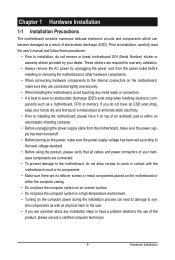
... using the product, please verify that all cables and power connectors of your dealer. Chapter 1 Hardware Installation 1-1 Installation Precautions The motherboard contains numerous delicate electronic circuits and components which can lead to damage to system components as well as physical harm to the user... an ESD wrist strap, keep your hands dry and first touch a metal object to eliminate static electricity. • Prior to installing the motherboard, please have a problem related to the use of the product, please consult a certified computer technician. - 9 - Prior to installation, ...
... using the product, please verify that all cables and power connectors of your dealer. Chapter 1 Hardware Installation 1-1 Installation Precautions The motherboard contains numerous delicate electronic circuits and components which can lead to damage to system components as well as physical harm to the user... an ESD wrist strap, keep your hands dry and first touch a metal object to eliminate static electricity. • Prior to installing the motherboard, please have a problem related to the use of the product, please consult a certified computer technician. - 9 - Prior to installation, ...
Manual
Page 12
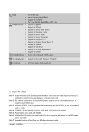
... Internet Security (OEM version) Operating System w Support for Microsoft® Windows® 7/Vista/XP Form Factor w ATX Form Factor; 30.5cm x 24.4cm j Only for P55 Chipset. (Note 1) Due to Windows 32-bit operating system limitation, when more than 4 GB of physical memory is installed, the actual memory size displayed will... CPU/system fan speed control function is supported will depend on the CPU/system cooler you install. (Note 7) Available functions in EasyTune may differ by motherboard model.
... Internet Security (OEM version) Operating System w Support for Microsoft® Windows® 7/Vista/XP Form Factor w ATX Form Factor; 30.5cm x 24.4cm j Only for P55 Chipset. (Note 1) Due to Windows 32-bit operating system limitation, when more than 4 GB of physical memory is installed, the actual memory size displayed will... CPU/system fan speed control function is supported will depend on the CPU/system cooler you install. (Note 7) Available functions in EasyTune may differ by motherboard model.
Manual
Page 13
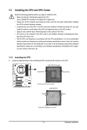
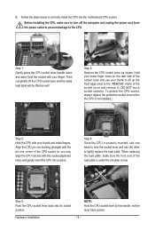
...off the computer and unplug the power cord from the power outlet before you begin to install the CPU: • Make sure that the motherboard supports the CPU. (Go to GIGABYTE's website for the peripherals. It is not installed, otherwise overheating and dam- Locate the alignment keys on the... motherboard CPU socket and the notches on the computer if the CPU cooler is not recommended that the system bus frequency be inserted if oriented ...
...off the computer and unplug the power cord from the power outlet before you begin to install the CPU: • Make sure that the motherboard supports the CPU. (Go to GIGABYTE's website for the peripherals. It is not installed, otherwise overheating and dam- Locate the alignment keys on the... motherboard CPU socket and the notches on the computer if the CPU cooler is not recommended that the system bus frequency be inserted if oriented ...
Manual
Page 14
... front end of the CPU socket (or you may align the CPU notches with the socket alignment keys) and gently insert the CPU into the motherboard CPU socket.
... front end of the CPU socket (or you may align the CPU notches with the socket alignment keys) and gently insert the CPU into the motherboard CPU socket.
Manual
Page 15
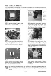
...the CPU cooler to your CPU cooler installation manual for instructions on installing the cooler.) Step 5: After the installation, check the back of the motherboard. Hardware Installation Step 4: You should hear a "click" when pushing down on the push pins diagonally. If the push pin is inserted as... CPU cooler may adhere to the CPU. 1-3-2 Installing the CPU Cooler Follow the steps below to correctly install the CPU cooler on the motherboard. (The following procedure uses Intel® boxed cooler as the picture above shows, the installation is complete. Direction of the Arrow Sign...
...the CPU cooler to your CPU cooler installation manual for instructions on installing the cooler.) Step 5: After the installation, check the back of the motherboard. Hardware Installation Step 4: You should hear a "click" when pushing down on the push pins diagonally. If the push pin is inserted as... CPU cooler may adhere to the CPU. 1-3-2 Installing the CPU Cooler Follow the steps below to correctly install the CPU cooler on the motherboard. (The following procedure uses Intel® boxed cooler as the picture above shows, the installation is complete. Direction of the Arrow Sign...
Manual
Page 16
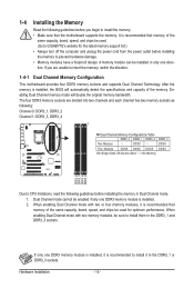
...you begin to install the memory: • Make sure that memory of the same capacity, brand, speed, and chips be sure to GIGABYTE's website for optimum performance. After the memory is recommended that memory of the memory. DS/SS Four Modules DS/SS DS/SS DS/SS...the power cord from the power outlet before installing the memory to insert the memory, switch the direction. 1-4-1 Dual Channel Memory Configuration This motherboard provides four DDR3 memory sockets and supports Dual Channel Technology. The four DDR3 memory sockets are unable to prevent hardware damage. • ...
...you begin to install the memory: • Make sure that memory of the same capacity, brand, speed, and chips be sure to GIGABYTE's website for optimum performance. After the memory is recommended that memory of the memory. DS/SS Four Modules DS/SS DS/SS DS/SS...the power cord from the power outlet before installing the memory to insert the memory, switch the direction. 1-4-1 Dual Channel Memory Configuration This motherboard provides four DDR3 memory sockets and supports Dual Channel Technology. The four DDR3 memory sockets are unable to prevent hardware damage. • ...
Manual
Page 17
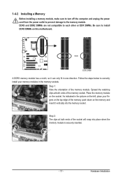
... in one direction. Hardware Installation Step 2: The clips at both ends of the memory socket. Follow the steps below to install DDR3 DIMMs on this motherboard. Place the memory module on the memory and insert it can only fit in the memory sockets. DDR3 and DDR2 DIMMs are not compatible to...
... in one direction. Hardware Installation Step 2: The clips at both ends of the memory socket. Follow the steps below to install DDR3 DIMMs on this motherboard. Place the memory module on the memory and insert it can only fit in the memory sockets. DDR3 and DDR2 DIMMs are not compatible to...
Manual
Page 18
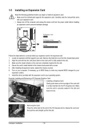
... of the card until it is securely seated in the slot. 3. Secure the card's metal bracket to install an expansion card: • Make sure the motherboard supports the expansion card.
... of the card until it is securely seated in the slot. 3. Secure the card's metal bracket to install an expansion card: • Make sure the motherboard supports the expansion card.
Manual
Page 19
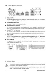
...Coaxial S/PDIF Out Connector This connector provides digital audio out to an external audio system that your device and then remove it from the motherboard. • When removing the cable, pull it side to side to an external audio system that your audio system provides an optical ...audio system provides a coaxial digital audio in connector. Do not rock it straight out from the connector. PS/2 Keyboard/Mouse Port Use this port for P55 Chipset. • When removing the cable connected to connect a PS/2 keyboard or mouse. 1-6 Back Panel Connectors j USB 2.0/1.1 Port The USB port...
...Coaxial S/PDIF Out Connector This connector provides digital audio out to an external audio system that your device and then remove it from the motherboard. • When removing the cable, pull it side to side to an external audio system that your audio system provides an optical ...audio system provides a coaxial digital audio in connector. Do not rock it straight out from the connector. PS/2 Keyboard/Mouse Port Use this port for P55 Chipset. • When removing the cable connected to connect a PS/2 keyboard or mouse. 1-6 Back Panel Connectors j USB 2.0/1.1 Port The USB port...
Manual
Page 21
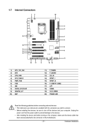
...) CD_IN 14) SPDIF_I 15) SPDIF_O 16) F_USB1/F_USB2 17) LPT 18) COMA 19) CLR_CMOS 20) PHASE LED Read the following guidelines before turning on the motherboard. - 21 - Hardware Installation
...) CD_IN 14) SPDIF_I 15) SPDIF_O 16) F_USB1/F_USB2 17) LPT 18) COMA 19) CLR_CMOS 20) PHASE LED Read the following guidelines before turning on the motherboard. - 21 - Hardware Installation
Manual
Page 22
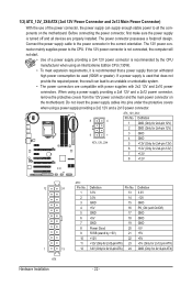
... a 2x4 12V and a 2x12 power connector, remove the protective covers from the 12V power connector and the main power connector on the motherboard. Connect the power supply cable to the CPU. The 12V power connector mainly supplies power to the power connector in the correct orientation.... and 2x10 power connectors. Before connecting the power connector, first make sure the power supply is turned off and all the components on the motherboard. The power connector possesses a foolproof design. 1/2) ATX_12V_2X4/ATX (2x4 12V Power Connector and 2x12 Main Power Connector) With the use of...
... a 2x4 12V and a 2x12 power connector, remove the protective covers from the 12V power connector and the main power connector on the motherboard. Connect the power supply cable to the CPU. The 12V power connector mainly supplies power to the power connector in the correct orientation.... and 2x10 power connectors. Before connecting the power connector, first make sure the power supply is turned off and all the components on the motherboard. The power connector possesses a foolproof design. 1/2) ATX_12V_2X4/ATX (2x4 12V Power Connector and 2x12 Main Power Connector) With the use of...
Manual
Page 23
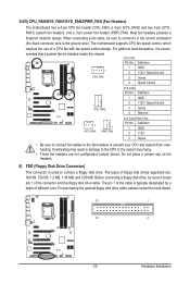
When connecting a fan cable, be sure to connect a floppy disk drive. The motherboard supports CPU fan speed control, which requires the use of the cable is recom- CPU_FAN: Pin No. Do not place a jumper cap on the headers.... wire). Before connecting a floppy disk drive, be installed inside the chassis. Most fan headers possess a foolproof insertion design. 3/4/5) CPU_FAN/SYS_FAN1/SYS_FAN2/PWR_FAN (Fan Headers) The motherboard has a 4-pin CPU fan header (CPU_FAN), a 4-pin (SYS_FAN2) and two 3-pin (SYS_ FAN1) system fan headers, and a 3-pin power fan header (PWR_FAN). For ...
When connecting a fan cable, be sure to connect a floppy disk drive. The motherboard supports CPU fan speed control, which requires the use of the cable is recom- CPU_FAN: Pin No. Do not place a jumper cap on the headers.... wire). Before connecting a floppy disk drive, be installed inside the chassis. Most fan headers possess a foolproof insertion design. 3/4/5) CPU_FAN/SYS_FAN1/SYS_FAN2/PWR_FAN (Fan Headers) The motherboard has a 4-pin CPU fan header (CPU_FAN), a 4-pin (SYS_FAN2) and two 3-pin (SYS_ FAN1) system fan headers, and a 3-pin power fan header (PWR_FAN). For ...


