Manual
Page 9
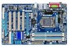
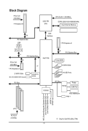
...DDR3 2200/1333/1066/800 MHz Dual Channel Memory x16 PCI Express Bus LAN RJ45 RTL8111D x1 PCI Express Bus x1 PCIe CLK (100 MHz) x1 1 PCI Express x1 2 SATA 3Gb/s ATA-133/100/66/33 IDE Channel GIGABYTE... SATA2 PCI Bus DMI Interface 1 PCI Express x4 Intel® P55 x4 PCI Express Bus ...Dual BIOS 6 SATA 3Gb/s 14 USB Ports CODEC LPC Bus IT8720 Floppy COM Port PS/2 KB/Mouse TPM j MIC (Center/Subwoofer Speaker Out) Line-Out (Front Speaker Out) Line-In (Rear Speaker Out) S/PDIF In S/PDIF Out 4 PCI PCI CLK (33 MHz) j Only for GA-P55...
...DDR3 2200/1333/1066/800 MHz Dual Channel Memory x16 PCI Express Bus LAN RJ45 RTL8111D x1 PCI Express Bus x1 PCIe CLK (100 MHz) x1 1 PCI Express x1 2 SATA 3Gb/s ATA-133/100/66/33 IDE Channel GIGABYTE... SATA2 PCI Bus DMI Interface 1 PCI Express x4 Intel® P55 x4 PCI Express Bus ...Dual BIOS 6 SATA 3Gb/s 14 USB Ports CODEC LPC Bus IT8720 Floppy COM Port PS/2 KB/Mouse TPM j MIC (Center/Subwoofer Speaker Out) Line-Out (Front Speaker Out) Line-In (Rear Speaker Out) S/PDIF In S/PDIF Out 4 PCI PCI CLK (33 MHz) j Only for GA-P55...
Manual
Page 12
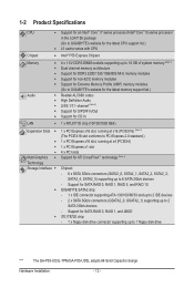
.../Intel® Core™ i5 series processor in the LGA1156 package (Go to GIGABYTE's website for the latest CPU support list.) L3 cache varies with CPU Chipset Intel® P55 Express Chipset Memory Audio 4 x 1.5V DDR3 DIMM sockets supporting up to 16 GB of system memory (Note 1) ... (Note 4) Technology Storage Interface Chipset: - 6 x SATA 3Gb/s connectors (SATA2_0, SATA2_1, SATA2_2, SATA2_3, SATA2_4, SATA2_5) supporting up to 1 floppy disk drive "*" The GA-P55-UD3L-TPM/GA-P55-UD3L adopts All-Solid Capacitor design.
.../Intel® Core™ i5 series processor in the LGA1156 package (Go to GIGABYTE's website for the latest CPU support list.) L3 cache varies with CPU Chipset Intel® P55 Express Chipset Memory Audio 4 x 1.5V DDR3 DIMM sockets supporting up to 16 GB of system memory (Note 1) ... (Note 4) Technology Storage Interface Chipset: - 6 x SATA 3Gb/s connectors (SATA2_0, SATA2_1, SATA2_2, SATA2_3, SATA2_4, SATA2_5) supporting up to 1 floppy disk drive "*" The GA-P55-UD3L-TPM/GA-P55-UD3L adopts All-Solid Capacitor design.
Manual
Page 18
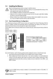
...Channel 0: DDR3_1, DDR3_2 Channel 1: DDR3_3, DDR3_4 Dual Channel Memory Configurations Table DDR3_2 DDR3_1 DDR3_4 DDR3_3 Two Modules - - The four DDR3 memory sockets are unable to install the memory: • Make sure that memory of the same capacity, brand, speed, and chips...memory, switch the direction. 1-4-1 Dual Channel Memory Configuration This motherboard provides four DDR3 memory sockets and supports Dual Channel Technology. If only one DDR3 memory module is recommended to GIGABYTE's website for optimum performance. Enabling Dual Channel memory mode will automatically detect ...
...Channel 0: DDR3_1, DDR3_2 Channel 1: DDR3_3, DDR3_4 Dual Channel Memory Configurations Table DDR3_2 DDR3_1 DDR3_4 DDR3_3 Two Modules - - The four DDR3 memory sockets are unable to install the memory: • Make sure that memory of the same capacity, brand, speed, and chips...memory, switch the direction. 1-4-1 Dual Channel Memory Configuration This motherboard provides four DDR3 memory sockets and supports Dual Channel Technology. If only one DDR3 memory module is recommended to GIGABYTE's website for optimum performance. Enabling Dual Channel memory mode will automatically detect ...
Manual
Page 19
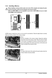
...one direction. Step 1: Note the orientation of the memory, push down on the memory and insert it can only fit in the memory sockets. DDR3 and DDR2 DIMMs are not compatible to each other or DDR DIMMs. Be sure to the memory module. Place the memory module on the socket.... Notch DDR3 DIMM A DDR3 memory module has a notch, so it vertically into place when the memory module is securely inserted. - 19 - 1-4-2 Installing a Memory Before installing a memory module,...
...one direction. Step 1: Note the orientation of the memory, push down on the memory and insert it can only fit in the memory sockets. DDR3 and DDR2 DIMMs are not compatible to each other or DDR DIMMs. Be sure to the memory module. Place the memory module on the socket.... Notch DDR3 DIMM A DDR3 memory module has a notch, so it vertically into place when the memory module is securely inserted. - 19 - 1-4-2 Installing a Memory Before installing a memory module,...
Manual
Page 74
... to specify a C.I.A.2 level and a Smart Fan mode. Grayed-out area(s) indicates that you must install a DDR3 1066 MHz memory module(s) (or above) to the hardware limitation, you fully know each function of these components. 4-3 EasyTune 6 GIGABYTE's EasyTune 6 is not supported. Before you do overclock/overvoltage in EasyTune 6 may occur. After making changes...
... to specify a C.I.A.2 level and a Smart Fan mode. Grayed-out area(s) indicates that you must install a DDR3 1066 MHz memory module(s) (or above) to the hardware limitation, you fully know each function of these components. 4-3 EasyTune 6 GIGABYTE's EasyTune 6 is not supported. Before you do overclock/overvoltage in EasyTune 6 may occur. After making changes...


