Manual
Page 9
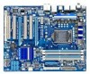
... no leftover screws or metal components placed on the motherboard or within the computer casing. • Do not place the computer system on an uneven surface. • Do not place the computer system in a high-temperature environment. • Turning on the motherboard, make...or other hardware components. • When connecting hardware components to the internal connectors on the computer power during the installation process can become damaged as a result of the product, please consult a certified computer technician. - 9 - ponents such as a motherboard, CPU or memory. Chapter 1 ...
... no leftover screws or metal components placed on the motherboard or within the computer casing. • Do not place the computer system on an uneven surface. • Do not place the computer system in a high-temperature environment. • Turning on the motherboard, make...or other hardware components. • When connecting hardware components to the internal connectors on the computer power during the installation process can become damaged as a result of the product, please consult a certified computer technician. - 9 - ponents such as a motherboard, CPU or memory. Chapter 1 ...
Manual
Page 13
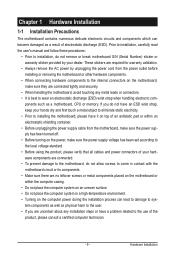
...socket.) • Apply an even and thin layer of thermal grease on the surface of the CPU. • Do not turn off the computer and unplug the power cord from the power outlet before installing the CPU to your hardware specifications including the CPU, graphics card, memory, hard ... not meet the standard requirements for the latest CPU support list.) • Always turn on the computer if the CPU cooler is not recommended that the motherboard supports the CPU. (Go to GIGABYTE's website for the peripherals. 1-3 Installing the CPU and CPU Cooler Read the following guidelines before you...
...socket.) • Apply an even and thin layer of thermal grease on the surface of the CPU. • Do not turn off the computer and unplug the power cord from the power outlet before installing the CPU to your hardware specifications including the CPU, graphics card, memory, hard ... not meet the standard requirements for the latest CPU support list.) • Always turn on the computer if the CPU cooler is not recommended that the motherboard supports the CPU. (Go to GIGABYTE's website for the peripherals. 1-3 Installing the CPU and CPU Cooler Read the following guidelines before you...
Manual
Page 14
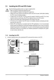
... CPU socket lever by the handle, not the lever base portion. Hardware Installation - 14 - When replacing the load plate, make sure to turn off the computer and unplug the power cord from the socket with your finger. Then completely lift the CPU socket lever and the metal load plate will be...
... CPU socket lever by the handle, not the lever base portion. Hardware Installation - 14 - When replacing the load plate, make sure to turn off the computer and unplug the power cord from the socket with your finger. Then completely lift the CPU socket lever and the metal load plate will be...
Manual
Page 16
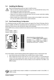
A memory module can be installed in the DDR3_1 and DDR3_3 sockets. When enabling Dual Channel mode with two memory modules, be used . (Go to GIGABYTE's website for optimum performance. Hardware Installation - 16 - DS/SS Four Modules DS/SS DS/SS DS/SS DS/SS (SS=Single-Sided, DS=Double-Sided,...; Make sure that memory of the memory. Dual Channel mode cannot be used for the latest memory support list.) • Always turn off the computer and unplug the power cord from the power outlet before installing the memory in the DDR3_1 or DDR3_3 sockets. If only one DDR3 memory module...
A memory module can be installed in the DDR3_1 and DDR3_3 sockets. When enabling Dual Channel mode with two memory modules, be used . (Go to GIGABYTE's website for optimum performance. Hardware Installation - 16 - DS/SS Four Modules DS/SS DS/SS DS/SS DS/SS (SS=Single-Sided, DS=Double-Sided,...; Make sure that memory of the memory. Dual Channel mode cannot be used for the latest memory support list.) • Always turn off the computer and unplug the power cord from the power outlet before installing the memory in the DDR3_1 or DDR3_3 sockets. If only one DDR3 memory module...
Manual
Page 17
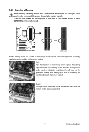
... compatible to each other or DDR DIMMs. Be sure to the memory module. 1-4-2 Installing a Memory Before installing a memory module, make sure to turn off the computer and unplug the power cord from the power outlet to prevent damage to install DDR3 DIMMs on this motherboard.
... compatible to each other or DDR DIMMs. Be sure to the memory module. 1-4-2 Installing a Memory Before installing a memory module, make sure to turn off the computer and unplug the power cord from the power outlet to prevent damage to install DDR3 DIMMs on this motherboard.
Manual
Page 18
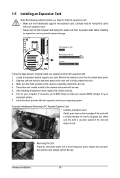
.... 3. Make sure the metal contacts on the top edge of the PCI Express slot to correctly install your expansion card. • Always turn off the computer and unplug the power cord from the chassis back panel. 2. Install the driver provided with your expansion card in your... computer. Carefully read the manual that supports your expansion card(s). 7. Remove the metal slot cover from the power outlet before you begin to prevent hardware damage. ...
.... 3. Make sure the metal contacts on the top edge of the PCI Express slot to correctly install your expansion card. • Always turn off the computer and unplug the power cord from the chassis back panel. 2. Install the driver provided with your expansion card in your... computer. Carefully read the manual that supports your expansion card(s). 7. Remove the metal slot cover from the power outlet before you begin to prevent hardware damage. ...
Manual
Page 21
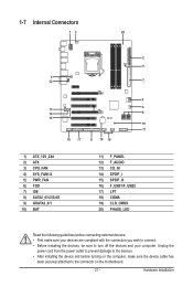
...; After installing the device and before connecting external devices: • First make sure the device cable has been securely attached to the connector on the computer, make sure your devices are compliant with the connectors you wish to connect. • Before installing the devices, be sure to turn off the devices...
...; After installing the device and before connecting external devices: • First make sure the device cable has been securely attached to the connector on the computer, make sure your devices are compliant with the connectors you wish to connect. • Before installing the devices, be sure to turn off the devices...
Manual
Page 22
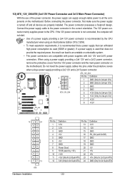
...) - 22 - The 12V power connector mainly supplies power to the power connector in the correct orientation. If the 12V power connector is not connected, the computer will not start. • Use of the power connector, the power supply can lead to an unstable or unbootable system. • The power connectors are...
...) - 22 - The 12V power connector mainly supplies power to the power connector in the correct orientation. If the 12V power connector is not connected, the computer will not start. • Use of the power connector, the power supply can lead to an unstable or unbootable system. • The power connectors are...
Manual
Page 25
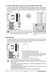
The GIGABYTE SATA2 controller supports RAID 0, RAID 1, and JBOD. Refer to Chapter 5, "Configuring SATA Hard Drive(s)," for 5 seconds.) 3. If more than two hard drives are compatible with SATA 1.5Gb/s standard. Plug in the power cord and restart your computer. • Always turn off your computer and unplug the...face up). • Used batteries must be an even number. Please connect the L-shaped end of the SATA 3Gb/s cable to your computer and unplug the power cord before replacing the battery. • Replace the battery with an equivalent one minute. (Or use a metal ...
The GIGABYTE SATA2 controller supports RAID 0, RAID 1, and JBOD. Refer to Chapter 5, "Configuring SATA Hard Drive(s)," for 5 seconds.) 3. If more than two hard drives are compatible with SATA 1.5Gb/s standard. Plug in the power cord and restart your computer. • Always turn off your computer and unplug the...face up). • Used batteries must be an even number. Please connect the L-shaped end of the SATA 3Gb/s cable to your computer and unplug the power cord before replacing the battery. • Replace the battery with an equivalent one minute. (Or use a metal ...
Manual
Page 26
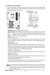
... the chassis front panel. The LED is off when the system is on the chassis front panel. Press the reset switch to restart the computer if the computer freezes and fails to perform a normal restart. • CI (Chassis Intrusion Header, Gray): Connects to the pin assignments below. This function requires a chassis with...
... the chassis front panel. The LED is off when the system is on the chassis front panel. Press the reset switch to restart the computer if the computer freezes and fails to perform a normal restart. • CI (Chassis Intrusion Header, Gray): Connects to the pin assignments below. This function requires a chassis with...
Manual
Page 29
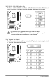
... plug the IEEE 1394 bracket (2x5-pin) cable into the USB header. • Prior to installing the USB bracket, be sure to turn off your computer and unplug the power cord from the power outlet to prevent damage to USB 2.0/1.1 specification. Each USB header can provide one parallel port via an...
... plug the IEEE 1394 bracket (2x5-pin) cable into the USB header. • Prior to installing the USB bracket, be sure to turn off your computer and unplug the power cord from the power outlet to prevent damage to USB 2.0/1.1 specification. Each USB header can provide one parallel port via an...
Manual
Page 30
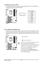
...configure the BIOS settings (refer to touch the two pins for BIOS configurations). To clear the CMOS values, place a jumper cap on your computer, be sure to remove the jumper cap from the power outlet before clearing the CMOS values. • After clearing the CMOS values and ...No Pin 19) CLR_CMOS (Clearing CMOS Jumper) Use this jumper to factory defaults. Open: Normal Short: Clear CMOS Values • Always turn off your computer and unplug the power cord from the jumper. Hardware Installation - 30 - Pin No. For purchasing the optional COM port cable, please contact the local...
...configure the BIOS settings (refer to touch the two pins for BIOS configurations). To clear the CMOS values, place a jumper cap on your computer, be sure to remove the jumper cap from the power outlet before clearing the CMOS values. • After clearing the CMOS values and ...No Pin 19) CLR_CMOS (Clearing CMOS Jumper) Use this jumper to factory defaults. Open: Normal Short: Clear CMOS Values • Always turn off your computer and unplug the power cord from the jumper. Hardware Installation - 30 - Pin No. For purchasing the optional COM port cable, please contact the local...

Manual
Page 34
...v6.00PG, An Energy Star Ally Copyright (C) 1984-2009, Award Software, Inc. Motherboard Model BIOS Version P55-UD3P D6 . . . . : BIOS Setup : XpressRecovery2 : Boot Menu : Qflash 07/08/2009-P55-7A89RG0JC-00 Function Keys Function Keys Function Keys: : POST SCREEN Press the key to Xpress Recovery2 during the... device without having to enter BIOS Setup first. To exit Boot Menu, press . 2-1 Startup Screen The following screens may appear when the computer boots. The LOGO Screen (Default) B. In Boot Menu, use the up hard drive data using the driver disk, the key can access...
...v6.00PG, An Energy Star Ally Copyright (C) 1984-2009, Award Software, Inc. Motherboard Model BIOS Version P55-UD3P D6 . . . . : BIOS Setup : XpressRecovery2 : Boot Menu : Qflash 07/08/2009-P55-7A89RG0JC-00 Function Keys Function Keys Function Keys: : POST SCREEN Press the key to Xpress Recovery2 during the... device without having to enter BIOS Setup first. To exit Boot Menu, press . 2-1 Startup Screen The following screens may appear when the computer boots. The LOGO Screen (Default) B. In Boot Menu, use the up hard drive data using the driver disk, the key can access...

Manual
Page 39
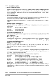
...) Enabled When the CPU or chipset detects that an overheating is occurring, PROCHOT signals will be reduced when the CPU is installed. With virtualization, one computer system can dynamically and effectively lower the CPU voltage and core frequency to let the CPU enter C3/C6/C7 mode in independent partitions. For...
...) Enabled When the CPU or chipset detects that an overheating is occurring, PROCHOT signals will be reduced when the CPU is installed. With virtualization, one computer system can dynamically and effectively lower the CPU voltage and core frequency to let the CPU enter C3/C6/C7 mode in independent partitions. For...
Manual
Page 40
.... Auto sets memory multiplier according to memory SPD data. (Default: Auto) Memory Frequency(Mhz) The first memory frequency value is designed to automatically adjust CPU computing power to read the SPD data on your system bus to the BCLK Frequency(Mhz) and System Memory Multiplier settings. Auto sets the PCIe clock...
.... Auto sets memory multiplier according to memory SPD data. (Default: Auto) Memory Frequency(Mhz) The first memory frequency value is designed to automatically adjust CPU computing power to read the SPD data on your system bus to the BCLK Frequency(Mhz) and System Memory Multiplier settings. Auto sets the PCIe clock...
Manual
Page 50
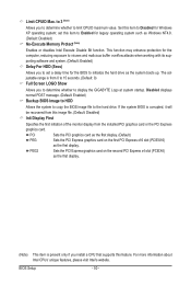
This function may enhance protection for the computer, reducing exposure to the hard drive. Disabled displays normal POST message. (Default: Enabled) Backup BIOS Image to HDD Allows the system to copy the BIOS ... Specifies the first initiation of the monitor display from 0 to 15 seconds. (Default: 0) Full Screen LOGO Show Allows you to determine whether to display the GIGABYTE Logo at system startup. justable range is present only if you to set this feature. BIOS Setup - 50 - to 3 (Note) Allows you to determine whether...
This function may enhance protection for the computer, reducing exposure to the hard drive. Disabled displays normal POST message. (Default: Enabled) Backup BIOS Image to HDD Allows the system to copy the BIOS ... Specifies the first initiation of the monitor display from 0 to 15 seconds. (Default: 0) Full Screen LOGO Show Allows you to determine whether to display the GIGABYTE Logo at system startup. justable range is present only if you to set this feature. BIOS Setup - 50 - to 3 (Note) Allows you to determine whether...

Manual
Page 54
... the system. Press and hold the power button for less than in the S1 state. S1(POS) Enables the system to be turned off the computer in a low power mode. If the power button is pressed for 4 seconds to RAM) sleep state (default). S3(STR) Enables the system to enter the...
... the system. Press and hold the power button for less than in the S1 state. S1(POS) Enables the system to be turned off the computer in a low power mode. If the power button is pressed for 4 seconds to RAM) sleep state (default). S3(STR) Enables the system to enter the...
Manual
Page 63
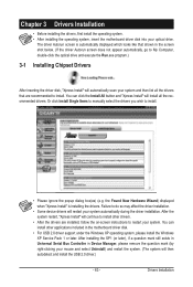
Failure to install. • Please ignore the popup dialog box(es) (e.g. You can install other drivers. • After the drivers are recommended to My Computer, double-click the optical drive and execute the Run.exe program.) 3-1 Installing Chipset Drivers After inserting the driver disk, "Xpress Install" will automatically scan your ...
Failure to install. • Please ignore the popup dialog box(es) (e.g. You can install other drivers. • After the drivers are recommended to My Computer, double-click the optical drive and execute the Run.exe program.) 3-1 Installing Chipset Drivers After inserting the driver disk, "Xpress Install" will automatically scan your ...

Manual
Page 68
Step 4: After the operating system is installed, right-click the Computer icon on the amount of data) and begin the installation of the operating system. Please note that if there is recommended; Step 2: When finished, go ...
Step 4: After the operating system is installed, right-click the Computer icon on the amount of data) and begin the installation of the operating system. Please note that if there is recommended; Step 2: When finished, go ...
Manual
Page 70
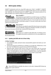
... BIOS. Extract the file and save the new BIOS file (e.g. p55ud3p.f1) to your computer by either pressing the key during the POST to update the system BIOS while in the .../SATA controller, use FAT32/16/12 file system. 3. Unique Features - 70 - 4-2 BIOS Update Utilities GIGABYTE motherboards provide two unique BIOS update tools, Q-Flash™ and @BIOS™. What is Q-Flash™?...the POST or pressing the key in system malfunction. P55-UD3P D6 . . . . : BIOS Setup : XpressRecovery2 : Boot Menu : Qflash 07/08/2009-P55-7A89RG0JC-00 Because BIOS flashing is corrupted or damaged,...
... BIOS. Extract the file and save the new BIOS file (e.g. p55ud3p.f1) to your computer by either pressing the key during the POST to update the system BIOS while in the .../SATA controller, use FAT32/16/12 file system. 3. Unique Features - 70 - 4-2 BIOS Update Utilities GIGABYTE motherboards provide two unique BIOS update tools, Q-Flash™ and @BIOS™. What is Q-Flash™?...the POST or pressing the key in system malfunction. P55-UD3P D6 . . . . : BIOS Setup : XpressRecovery2 : Boot Menu : Qflash 07/08/2009-P55-7A89RG0JC-00 Because BIOS flashing is corrupted or damaged,...


