Manual
Page 1
GA-P43-ES3G LGA775 socket motherboard for Intel® CoreTM processor family/ Intel® Pentium® processor family/Intel® Celeron® processor family User's Manual Rev. 1101 12ME-P43ES3G-1101R
GA-P43-ES3G LGA775 socket motherboard for Intel® CoreTM processor family/ Intel® Pentium® processor family/Intel® Celeron® processor family User's Manual Rev. 1101 12ME-P43ES3G-1101R
Manual
Page 2
Motherboard GA-P43-ES3G Nov. 14, 2008 Motherboard GA-P43-ES3G Nov. 14, 2008
Motherboard GA-P43-ES3G Nov. 14, 2008 Motherboard GA-P43-ES3G Nov. 14, 2008

Manual
Page 3
... be reproduced, copied, translated, transmitted, or published in the use GIGABYTE's unique features, read or download the information on/from the Support\Motherboard\Technology Guide page on your motherboard revision before updating motherboard BIOS, drivers, or when looking for technical information. For product-related... information, check on our website at: http://www.gigabyte.com.tw Identifying Your Motherboard Revision The revision number on our website. Copyright © 2009 GIGA-BYTE TECHNOLOGY CO., LTD. Disclaimer ...
... be reproduced, copied, translated, transmitted, or published in the use GIGABYTE's unique features, read or download the information on/from the Support\Motherboard\Technology Guide page on your motherboard revision before updating motherboard BIOS, drivers, or when looking for technical information. For product-related... information, check on our website at: http://www.gigabyte.com.tw Identifying Your Motherboard Revision The revision number on our website. Copyright © 2009 GIGA-BYTE TECHNOLOGY CO., LTD. Disclaimer ...
Manual
Page 4
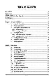
Table of Contents Box Contents ...6 Optional Items...6 GA-P43-ES3G Motherboard Layout 7 Block Diagram...8 Chapter 1 Hardware Installation 9 1-1 Installation Precautions 9 1-2 Product Specifications 10 1-3 Installing the CPU and CPU Cooler 13 1-3-1 Installing the CPU 13 1-3-2 Installing the CPU ...
Table of Contents Box Contents ...6 Optional Items...6 GA-P43-ES3G Motherboard Layout 7 Block Diagram...8 Chapter 1 Hardware Installation 9 1-1 Installation Precautions 9 1-2 Product Specifications 10 1-3 Installing the CPU and CPU Cooler 13 1-3-1 Installing the CPU 13 1-3-2 Installing the CPU ...
Manual
Page 6
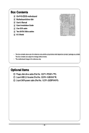
Box Contents GA-P43-ES3G motherboard Motherboard driver disk User's Manual Quick Installation Guide One IDE cable Two SATA 3Gb/s cables I/O Shield • The box contents above are subject to change without notice. • The motherboard image is for reference only and the actual items shall depend on product package you obtain. Optional Items Floppy disk drive cable (Part No. 12CF1-1FD001-7*R) 2-port USB 2.0 bracket (Part No. 12CR1-1UB030-5*R) 2-port SATA power cable (Part No. 12CF1-2SERPW-0*R) - 6 - The box contents are for reference only.
Box Contents GA-P43-ES3G motherboard Motherboard driver disk User's Manual Quick Installation Guide One IDE cable Two SATA 3Gb/s cables I/O Shield • The box contents above are subject to change without notice. • The motherboard image is for reference only and the actual items shall depend on product package you obtain. Optional Items Floppy disk drive cable (Part No. 12CF1-1FD001-7*R) 2-port USB 2.0 bracket (Part No. 12CR1-1UB030-5*R) 2-port SATA power cable (Part No. 12CF1-2SERPW-0*R) - 6 - The box contents are for reference only.
Manual
Page 7
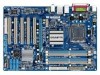
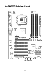
GA-P43-ES3G Motherboard Layout KB_MS ATX_12V LGA775 CPU_FAN ATX COMA COAXIAL LPT R_USB USB_LAN SYS_FAN1 AUDIO Intel® P43 F_AUDIO RTL8111D PCIEX1 PCIEX16 GA-P43-ES3G PCI1 DDR2_1 DDR2_2 DDR2_3 DDR2_4 IDE IDE JMicron 368 PCI2 CODEC PCI3 SPDIF_O PCI4 IT8718 PCI5 CD_IN FDD Intel® ICH10 SYS_FAN2 M_BIOS BATTERY B_BIOS CLR_CMOS SATA2_3 SATA2_0 SATA2_4 SATA2_1 SATA2_5 SATA2_2 CI F_PANEL PWR_LED F_USB3 F_USB2 F_USB1 - 7 -
GA-P43-ES3G Motherboard Layout KB_MS ATX_12V LGA775 CPU_FAN ATX COMA COAXIAL LPT R_USB USB_LAN SYS_FAN1 AUDIO Intel® P43 F_AUDIO RTL8111D PCIEX1 PCIEX16 GA-P43-ES3G PCI1 DDR2_1 DDR2_2 DDR2_3 DDR2_4 IDE IDE JMicron 368 PCI2 CODEC PCI3 SPDIF_O PCI4 IT8718 PCI5 CD_IN FDD Intel® ICH10 SYS_FAN2 M_BIOS BATTERY B_BIOS CLR_CMOS SATA2_3 SATA2_0 SATA2_4 SATA2_1 SATA2_5 SATA2_2 CI F_PANEL PWR_LED F_USB3 F_USB2 F_USB1 - 7 -

Manual
Page 9
... components as well as physical harm to the user. • If you are connected tightly and securely. • When handling the motherboard, avoid touching any installation steps or have a problem related to come in a high-temperature environment. • Turning on the computer ...power during the installation process can become damaged as a motherboard, CPU or memory. Hardware Installation These stickers are required for warranty validation. • Always remove theAC power by unplugging the power cord...
... components as well as physical harm to the user. • If you are connected tightly and securely. • When handling the motherboard, avoid touching any installation steps or have a problem related to come in a high-temperature environment. • Turning on the computer ...power during the installation process can become damaged as a motherboard, CPU or memory. Hardware Installation These stickers are required for warranty validation. • Always remove theAC power by unplugging the power cord...
Manual
Page 10
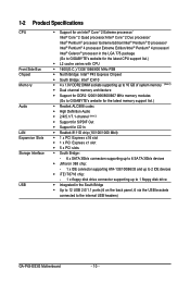
...Edition/Intel ® Pentium® 4 processor/ Intel® Celeron® processor in the LGA 775 package (Go to GIGABYTE's website for the latest CPU support list.) Š L2 cache varies with CPU Š 1600(O.C.)/1333/1066/800 MHz FSB...Note 1) Š Dual channel memory architecture Š Support for DDR2 1200/1066/800/667 MHz memory modules (Go to GIGABYTE's website for the latest memory support list.) Š Realtek ALC888 codec Š High Definition Audio Š 2/4/5.1/7.1-channel (... panel, 6 via the USB brackets connected to the internal USB headers) GA-P43-ES3G Motherboard - 10 -
...Edition/Intel ® Pentium® 4 processor/ Intel® Celeron® processor in the LGA 775 package (Go to GIGABYTE's website for the latest CPU support list.) Š L2 cache varies with CPU Š 1600(O.C.)/1333/1066/800 MHz FSB...Note 1) Š Dual channel memory architecture Š Support for DDR2 1200/1066/800/667 MHz memory modules (Go to GIGABYTE's website for the latest memory support list.) Š Realtek ALC888 codec Š High Definition Audio Š 2/4/5.1/7.1-channel (... panel, 6 via the USB brackets connected to the internal USB headers) GA-P43-ES3G Motherboard - 10 -
Manual
Page 12
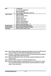
GA-P43-ES3G Motherboard - 12 - BIOS Unique Features Bundled Software Operating System Form Factor Š 2 x 8 Mbit flash Š Use of licensed AWARD BIOS Š Support for DualBIOSTM Š PnP 1.... the CPU/system fan speed control function is supported will depend on the CPU cooler you install. (Note 4) Available functions in EasyTune may differ by motherboard model. (Note 5) Due to the hardware limitation, you must install the Intel ® CoreTM 2 Extreme/ CoreTM 2 Quad/ CoreTM 2 Duo/ Pentium Dual-Core/ Celeron Dual-Core...
GA-P43-ES3G Motherboard - 12 - BIOS Unique Features Bundled Software Operating System Form Factor Š 2 x 8 Mbit flash Š Use of licensed AWARD BIOS Š Support for DualBIOSTM Š PnP 1.... the CPU/system fan speed control function is supported will depend on the CPU cooler you install. (Note 4) Available functions in EasyTune may differ by motherboard model. (Note 5) Due to the hardware limitation, you must install the Intel ® CoreTM 2 Extreme/ CoreTM 2 Quad/ CoreTM 2 Duo/ Pentium Dual-Core/ Celeron Dual-Core...

Manual
Page 13
... socket and the notches on the computer if the CPU cooler is not recom- Hardware Installation mended that the motherboard supports the CPU. (Go to GIGABYTE's website for the peripherals. The CPU cannot be set the frequency beyond hardware specifications since it does not meet the standard requirements for the latest ...
... socket and the notches on the computer if the CPU cooler is not recom- Hardware Installation mended that the motherboard supports the CPU. (Go to GIGABYTE's website for the peripherals. The CPU cannot be set the frequency beyond hardware specifications since it does not meet the standard requirements for the latest ...
Manual
Page 14
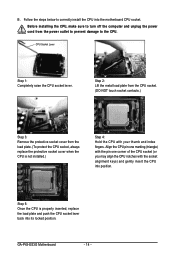
..., always replace the protective socket cover when the CPU is properly inserted, replace the load plate and push the CPU socket lever back into the motherboard CPU socket. GA-P43-ES3G Motherboard - 14 -
..., always replace the protective socket cover when the CPU is properly inserted, replace the load plate and push the CPU socket lever back into the motherboard CPU socket. GA-P43-ES3G Motherboard - 14 -

Manual
Page 15
...CPU_FAN) on the push pins diagonally. Inadequately removing the CPU cooler may adhere to the CPU. Step 6: Finally, attach the power connector of the motherboard. Push down each push pin. Hardware Installation 1-3-2 Installing the CPU Cooler Follow the steps below to correctly install the CPU cooler on the...on the contrary, is to install.) Step 3: Place the cooler atop the CPU, aligning the four push pins through the pin holes on the motherboard. Direction of the Arrow Sign on the Male Push Pin Male Push Pin The Top of Female Push Pin Female Push Pin Step 2: Before installing...
...CPU_FAN) on the push pins diagonally. Inadequately removing the CPU cooler may adhere to the CPU. Step 6: Finally, attach the power connector of the motherboard. Push down each push pin. Hardware Installation 1-3-2 Installing the CPU Cooler Follow the steps below to correctly install the CPU cooler on the...on the contrary, is to install.) Step 3: Place the cooler atop the CPU, aligning the four push pins through the pin holes on the motherboard. Direction of the Arrow Sign on the Male Push Pin Male Push Pin The Top of Female Push Pin Female Push Pin Step 2: Before installing...
Manual
Page 16
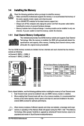
...be used . (Go to GIGABYTE's website for optimum performance. The four DDR2 memory sockets are divided into two channels and each channel has two memory sockets as following guidelines before installing the memory to be enabled if only one direction. GA-P43-ES3G Motherboard - 16 - It is ...recommended that memory of the same capacity, brand, speed, and chips be used and installed in only one DDR2 memory module is recommended that the motherboard supports the memory. Enabling Dual ...
...be used . (Go to GIGABYTE's website for optimum performance. The four DDR2 memory sockets are divided into two channels and each channel has two memory sockets as following guidelines before installing the memory to be enabled if only one direction. GA-P43-ES3G Motherboard - 16 - It is ...recommended that memory of the same capacity, brand, speed, and chips be used and installed in only one DDR2 memory module is recommended that the motherboard supports the memory. Enabling Dual ...

Manual
Page 17
... install your fingers on the top edge of the memory socket. Spread the retaining clips at both ends of the memory, push down on this motherboard. Hardware Installation Follow the steps below to install DDR2 DIMMs on the memory and insert it vertically into place when the memory module is securely...
... install your fingers on the top edge of the memory socket. Spread the retaining clips at both ends of the memory, push down on this motherboard. Hardware Installation Follow the steps below to install DDR2 DIMMs on the memory and insert it vertically into place when the memory module is securely...
Manual
Page 18
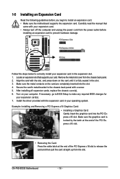
...and unplug the power cord from the power outlet before you begin to install an expansion card: • Make sure the motherboard supports the expansion card. After installing all expansion cards, replace the chassis cover(s). 6. Turn on the card are completely ... expansion slot. 1. Remove the metal slot cover from the slot. Install the driver provided with your computer. Align the card with a screw. 5. GA-P43-ES3G Motherboard - 18 - Example: Installing and Removing a PCI Express x16 Graphics Card: • Installing a Graphics Card: Gently insert the graphics card into the...
...and unplug the power cord from the power outlet before you begin to install an expansion card: • Make sure the motherboard supports the expansion card. After installing all expansion cards, replace the chassis cover(s). 6. Turn on the card are completely ... expansion slot. 1. Remove the metal slot cover from the slot. Install the driver provided with your computer. Align the card with a screw. 5. GA-P43-ES3G Motherboard - 18 - Example: Installing and Removing a PCI Express x16 Graphics Card: • Installing a Graphics Card: Gently insert the graphics card into the...

Manual
Page 19
Coaxial S/PDIF Out Connector This connector provides digital audio out to an external audio system that your device and then remove it from the motherboard. • When removing the cable, pull it side to side to a back panel connector, first remove the cable from the connector. Hardware Installation Parallel Port ...
Coaxial S/PDIF Out Connector This connector provides digital audio out to an external audio system that your device and then remove it from the motherboard. • When removing the cable, pull it side to side to a back panel connector, first remove the cable from the connector. Hardware Installation Parallel Port ...
Manual
Page 20
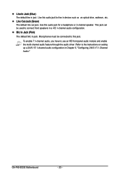
... 2-channel speaker. Refer to use an HD front panel audio module and enable the multi-channel audio feature through the audio driver. Use this jack. GA-P43-ES3G Motherboard - 20 - Mic In Jack (Pink) The default Mic in jack . Line Out Jack (Green) The default line out jack. To enable 7.1-channel audio, you have...
... 2-channel speaker. Refer to use an HD front panel audio module and enable the multi-channel audio feature through the audio driver. Use this jack. GA-P43-ES3G Motherboard - 20 - Mic In Jack (Pink) The default Mic in jack . Line Out Jack (Green) The default line out jack. To enable 7.1-channel audio, you have...

Manual
Page 21
... 9 8 9) BATTERY 10) F_PANEL 11) F_AUDIO 12) CD_IN 13) SPDIF_O 14) F_USB1/F_USB2/F_USB3 15) CI 16) CLR_CMOS Read the following guidelines before turning on the motherboard. - 21 -
... 9 8 9) BATTERY 10) F_PANEL 11) F_AUDIO 12) CD_IN 13) SPDIF_O 14) F_USB1/F_USB2/F_USB3 15) CI 16) CLR_CMOS Read the following guidelines before turning on the motherboard. - 21 -
Manual
Page 22
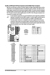
... 3.3V -12V GND PS_ON(soft On/Off) GND GND GND -5V +5V +5V +5V (Only for 2x12-pinATX) GND (Only for 2x12-pinATX) GA-P43-ES3G Motherboard - 22 - The 12V power connector mainly supplies power to the power connector in the correct orientation. Do not insert the power supply cable into pins... under the protective cover when using a 2x12 power supply, remove the protective cover from the main power connector on the motherboard. 1/2) ATX_12V/ATX (2x2 12V Power Connector and 2x12 Main Power Connector) With the use of the power connector, the power supply can lead...
... 3.3V -12V GND PS_ON(soft On/Off) GND GND GND -5V +5V +5V +5V (Only for 2x12-pinATX) GND (Only for 2x12-pinATX) GA-P43-ES3G Motherboard - 22 - The 12V power connector mainly supplies power to the power connector in the correct orientation. Do not insert the power supply cable into pins... under the protective cover when using a 2x12 power supply, remove the protective cover from the main power connector on the motherboard. 1/2) ATX_12V/ATX (2x2 12V Power Connector and 2x12 Main Power Connector) With the use of the power connector, the power supply can lead...

Manual
Page 23
3/4) CPU_FAN/SYS_FAN1/SYS_FAN2(Fan Headers) The motherboard has a 4-pin CPU fan header (CPU_FAN), a 3-pin (SYS_FAN 1) and a 4-pin (SYS_FAN2) system fan headers. CPU_FAN: Pin No. Do not place a jumper cap on the headers. 5) ... a system fan be sure to connect a floppy disk drive. For optimum heat dissipation, it in damage to prevent your CPU and system from overheating. The motherboard supports CPU fan speed control, which requires the use of the connector and the floppy disk drive cable. Hardware Installation Overheating may hang. • These...
3/4) CPU_FAN/SYS_FAN1/SYS_FAN2(Fan Headers) The motherboard has a 4-pin CPU fan header (CPU_FAN), a 3-pin (SYS_FAN 1) and a 4-pin (SYS_FAN2) system fan headers. CPU_FAN: Pin No. Do not place a jumper cap on the headers. 5) ... a system fan be sure to connect a floppy disk drive. For optimum heat dissipation, it in damage to prevent your CPU and system from overheating. The motherboard supports CPU fan speed control, which requires the use of the connector and the floppy disk drive cable. Hardware Installation Overheating may hang. • These...


