Manual
Page 1
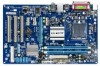
GA-P41T-ES3G LGA775 socket motherboard for Intel® Core™ processor family/ Intel® Pentium® processor family/Intel® Celeron® processor family User's Manual Rev. 1001 12ME-P41TE3G-1001R
GA-P41T-ES3G LGA775 socket motherboard for Intel® Core™ processor family/ Intel® Pentium® processor family/Intel® Celeron® processor family User's Manual Rev. 1001 12ME-P41TE3G-1001R

Manual
Page 2
Motherboard GA-P41T-ES3G Nov. 20, 2009 Motherboard GA-P41T-ES3G Nov. 20, 2009
Motherboard GA-P41T-ES3G Nov. 20, 2009 Motherboard GA-P41T-ES3G Nov. 20, 2009
Manual
Page 3
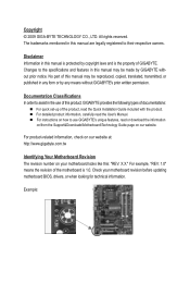
... Information in this : "REV: X.X." For product-related information, check on our website at: http://www.gigabyte.com.tw Identifying Your Motherboard Revision The revision number on your motherboard revision before updating motherboard BIOS, drivers, or when looking for technical information. Copyright © 2009 GIGA-BYTE TECHNOLOGY CO., LTD. Changes to the specifications and features...
... Information in this : "REV: X.X." For product-related information, check on our website at: http://www.gigabyte.com.tw Identifying Your Motherboard Revision The revision number on your motherboard revision before updating motherboard BIOS, drivers, or when looking for technical information. Copyright © 2009 GIGA-BYTE TECHNOLOGY CO., LTD. Changes to the specifications and features...
Manual
Page 4
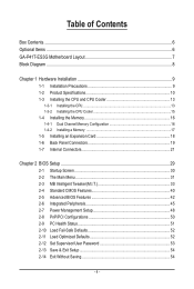
Table of Contents Box Contents...6 Optional Items...6 GA-P41T-ES3G Motherboard Layout 7 Block Diagram...8 Chapter 1 Hardware Installation 9 1-1 Installation Precautions 9 1-2 Product Specifications 10 1-3 Installing the CPU and CPU Cooler 13 1-3-1 Installing the CPU 13 1-3-2 Installing the CPU ...
Table of Contents Box Contents...6 Optional Items...6 GA-P41T-ES3G Motherboard Layout 7 Block Diagram...8 Chapter 1 Hardware Installation 9 1-1 Installation Precautions 9 1-2 Product Specifications 10 1-3 Installing the CPU and CPU Cooler 13 1-3-1 Installing the CPU 13 1-3-2 Installing the CPU ...
Manual
Page 6
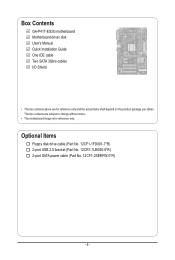
Box Contents GA-P41T-ES3G motherboard Motherboard driver disk User's Manual Quick Installation Guide One IDE cable Two SATA 3Gb/s cables I/O Shield • The box contents above are subject to change without notice. • The motherboard image is for reference only and the actual items shall depend on the product package you obtain. Optional Items Floppy disk drive cable (Part No. 12CF1-1FD001-7*R) 2-port USB 2.0 bracket (Part No. 12CR1-1UB030-5*R) 2-port SATA power cable (Part No. 12CF1-2SERPW-0*R) - 6 - The box contents are for reference only.
Box Contents GA-P41T-ES3G motherboard Motherboard driver disk User's Manual Quick Installation Guide One IDE cable Two SATA 3Gb/s cables I/O Shield • The box contents above are subject to change without notice. • The motherboard image is for reference only and the actual items shall depend on the product package you obtain. Optional Items Floppy disk drive cable (Part No. 12CF1-1FD001-7*R) 2-port USB 2.0 bracket (Part No. 12CR1-1UB030-5*R) 2-port SATA power cable (Part No. 12CF1-2SERPW-0*R) - 6 - The box contents are for reference only.
Manual
Page 9
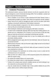
... computer system on an uneven surface. • Do not place the computer system in a high-temperature environment. • Turning on the motherboard, make sure the power supply voltage has been set according to the local voltage standard. • Before using the product, please verify that... all cables and power connectors of your dealer. If you are connected tightly and securely. • When handling the motherboard, avoid touching any installation steps or have a problem related to the use of electrostatic discharge (ESD). ponents such as physical harm to ...
... computer system on an uneven surface. • Do not place the computer system in a high-temperature environment. • Turning on the motherboard, make sure the power supply voltage has been set according to the local voltage standard. • Before using the product, please verify that... all cables and power connectors of your dealer. If you are connected tightly and securely. • When handling the motherboard, avoid touching any installation steps or have a problem related to the use of electrostatic discharge (ESD). ponents such as physical harm to ...

Manual
Page 12
... 2) Whether the CPU fan speed control function is supported will depend on the CPU cooler you install. (Note 3) Available functions in EasyTune may differ by motherboard model. (Note 4) Due to the hardware limitation, you must install the Intel® Core™ 2 Extreme/ Core™ 2 Quad/ Core™ 2 Duo/ Pentium Dual-Core...
... 2) Whether the CPU fan speed control function is supported will depend on the CPU cooler you install. (Note 3) Available functions in EasyTune may differ by motherboard model. (Note 4) Due to the hardware limitation, you must install the Intel® Core™ 2 Extreme/ Core™ 2 Quad/ Core™ 2 Duo/ Pentium Dual-Core...
Manual
Page 13
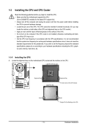
... the CPU. • Do not turn on the computer if the CPU cooler is not recommended that the motherboard supports the CPU. (Go to GIGABYTE's website for the peripherals. Locate the alignment keys on the motherboard CPU socket and the notches on the CPU - 13 - LGA775 CPU Socket Alignment Key LGA775 CPU Alignment...
... the CPU. • Do not turn on the computer if the CPU cooler is not recommended that the motherboard supports the CPU. (Go to GIGABYTE's website for the peripherals. Locate the alignment keys on the motherboard CPU socket and the notches on the CPU - 13 - LGA775 CPU Socket Alignment Key LGA775 CPU Alignment...

Manual
Page 14
..., always replace the protective socket cover when the CPU is properly inserted, replace the load plate and push the CPU socket lever back into the motherboard CPU socket. Step 5: Once the CPU is not installed.) Step 4: Hold the CPU with the socket alignment keys) and gently insert the CPU into position...
..., always replace the protective socket cover when the CPU is properly inserted, replace the load plate and push the CPU socket lever back into the motherboard CPU socket. Step 5: Once the CPU is not installed.) Step 4: Hold the CPU with the socket alignment keys) and gently insert the CPU into position...
Manual
Page 15
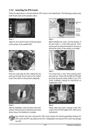
.... If the push pin is inserted as the example cooler.) Step 1: Apply an even and thin layer of thermal grease on the surface of the motherboard. Push down each push pin. Hardware Installation 1-3-2 Installing the CPU Cooler Follow the steps below to correctly install the CPU cooler on the... above shows, the installation is to install.) Step 3: Place the cooler atop the CPU, aligning the four push pins through the pin holes on the motherboard. Direction of the Arrow Sign on the Male Push Pin Male Push Pin The Top of Female Push Pin Female Push Pin Step 2: Before installing...
.... If the push pin is inserted as the example cooler.) Step 1: Apply an even and thin layer of thermal grease on the surface of the motherboard. Push down each push pin. Hardware Installation 1-3-2 Installing the CPU Cooler Follow the steps below to correctly install the CPU cooler on the... above shows, the installation is to install.) Step 3: Place the cooler atop the CPU, aligning the four push pins through the pin holes on the motherboard. Direction of the Arrow Sign on the Male Push Pin Male Push Pin The Top of Female Push Pin Female Push Pin Step 2: Before installing...

Manual
Page 16
... two DDR3 memory sockets and supports Dual Channel Technology. After the memory is recommended that the motherboard supports the memory. The two DDR3 memory sockets are unable to GIGABYTE's website for the latest memory support list.) • Always turn off the computer and unplug the power cord from the power outlet before...
... two DDR3 memory sockets and supports Dual Channel Technology. After the memory is recommended that the motherboard supports the memory. The two DDR3 memory sockets are unable to GIGABYTE's website for the latest memory support list.) • Always turn off the computer and unplug the power cord from the power outlet before...

Manual
Page 17
... the orientation of the memory, push down on the memory and insert it can only fit in one direction. Place the memory module on this motherboard. Step 2: The clips at both ends of the memory socket. 1-4-2 Installing a Memory Before installing a memory module, make sure to turn off the computer and unplug...
... the orientation of the memory, push down on the memory and insert it can only fit in one direction. Place the memory module on this motherboard. Step 2: The clips at both ends of the memory socket. 1-4-2 Installing a Memory Before installing a memory module, make sure to turn off the computer and unplug...
Manual
Page 18
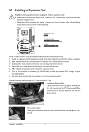
... card in your computer. Remove the metal slot cover from the power outlet before you begin to install an expansion card: • Make sure the motherboard supports the expansion card. Make sure the metal contacts on the card are completely inserted into the PCI Express slot. After installing all expansion cards...
... card in your computer. Remove the metal slot cover from the power outlet before you begin to install an expansion card: • Make sure the motherboard supports the expansion card. Make sure the metal contacts on the card are completely inserted into the PCI Express slot. After installing all expansion cards...

Manual
Page 19
... Port The Gigabit Ethernet LAN port provides Internet connection at up to an external audio system that your device and then remove it from the motherboard. • When removing the cable, pull it side to side to connect devices such as a printer, scanner and etc. Parallel Port Use the parallel port...
... Port The Gigabit Ethernet LAN port provides Internet connection at up to an external audio system that your device and then remove it from the motherboard. • When removing the cable, pull it side to side to connect devices such as a printer, scanner and etc. Parallel Port Use the parallel port...

Manual
Page 21
... devices and your devices are compliant with the connectors you wish to connect. • Before installing the devices, be sure to the connector on the motherboard. - 21 - 1-7 Internal Connectors 1 3 10 4 15 11 12 1) ATX_12V 2) ATX 3) CPU_FAN 4) SYS_FAN1/SYS_FAN2 5) PWR_FAN 6) FDD 7) IDE 8) SATA2_0/1/2/3 7 2 9 14 5 8 6 13 4 9) 10) 11) 12) 13) 14) 15) F_PANEL...
... devices and your devices are compliant with the connectors you wish to connect. • Before installing the devices, be sure to the connector on the motherboard. - 21 - 1-7 Internal Connectors 1 3 10 4 15 11 12 1) ATX_12V 2) ATX 3) CPU_FAN 4) SYS_FAN1/SYS_FAN2 5) PWR_FAN 6) FDD 7) IDE 8) SATA2_0/1/2/3 7 2 9 14 5 8 6 13 4 9) 10) 11) 12) 13) 14) 15) F_PANEL...

Manual
Page 22
... power connector is not connected, the computer will not start. • To meet expansion requirements, it is turned off and all the components on the motherboard. The 12V power connector mainly supplies power to all devices are properly installed. When using a 2x10 power supply. 3 4 1 2 ATX_12V ATX_12V: Pin ...into pins under the protective cover when using a 2x12 power supply, remove the protective cover from the main power connector on the motherboard. 1/2) ATX_12V/ATX (2x2 12V Power Connector and 2x12 Main Power Connector) With the use of the power connector, the power ...
... power connector is not connected, the computer will not start. • To meet expansion requirements, it is turned off and all the components on the motherboard. The 12V power connector mainly supplies power to all devices are properly installed. When using a 2x10 power supply. 3 4 1 2 ATX_12V ATX_12V: Pin ...into pins under the protective cover when using a 2x12 power supply, remove the protective cover from the main power connector on the motherboard. 1/2) ATX_12V/ATX (2x2 12V Power Connector and 2x12 Main Power Connector) With the use of the power connector, the power ...

Manual
Page 23
The motherboard supports CPU fan speed control, which requires the use of different color. For optimum heat dissipation, it in damage to the CPU or the system ...: Pin No. For purchasing the optional floppy disk drive cable, please contact the local dealer. 33 1 34 2 - 23 - 3/4/5) CPU_FAN/SYS_FAN1/SYS_FAN2/PWR_FAN (Fan Headers) The motherboard has a 4-pin CPU fan header (CPU_FAN), two 3-pin system fan headers (SYS_FAN1 and SYS_FAN2), and a 3-pin power fan header (PWR_FAN). Overheating may result in the...
The motherboard supports CPU fan speed control, which requires the use of different color. For optimum heat dissipation, it in damage to the CPU or the system ...: Pin No. For purchasing the optional floppy disk drive cable, please contact the local dealer. 33 1 34 2 - 23 - 3/4/5) CPU_FAN/SYS_FAN1/SYS_FAN2/PWR_FAN (Fan Headers) The motherboard has a 4-pin CPU fan header (CPU_FAN), two 3-pin system fan headers (SYS_FAN1 and SYS_FAN2), and a 3-pin power fan header (PWR_FAN). Overheating may result in the...

Manual
Page 26
... Chapter 5, "Configuring 2/4/5.1/7.1-Channel Audio." • Some chassis provide a front panel audio module that has separated connectors on both of the motherboard header. Incorrect connection between the module connector and the motherboard header will be present on each wire instead of a single plug. If you want to mute the back panel audio (only...
... Chapter 5, "Configuring 2/4/5.1/7.1-Channel Audio." • Some chassis provide a front panel audio module that has separated connectors on both of the motherboard header. Incorrect connection between the module connector and the motherboard header will be present on each wire instead of a single plug. If you want to mute the back panel audio (only...
Manual
Page 27
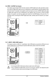
For example, some graphics cards may require you to use a S/PDIF digital audio cable for digital audio output from your motherboard to your graphics card if you wish to connect an HDMI display to the USB bracket. - 27 - For purchasing the optional... Out Header) This header supports digital S/PDIF Out and connects a S/PDIF digital audio cable (provided by expansion cards) for digital audio output from your motherboard to USB 2.0/1.1 specification. Definition 1 1 SPDIFO 2 GND 13) F_USB1/F_USB2 (USB Headers) The headers conform to certain expansion cards like graphics cards and...
For example, some graphics cards may require you to use a S/PDIF digital audio cable for digital audio output from your motherboard to your graphics card if you wish to connect an HDMI display to the USB bracket. - 27 - For purchasing the optional... Out Header) This header supports digital S/PDIF Out and connects a S/PDIF digital audio cable (provided by expansion cards) for digital audio output from your motherboard to USB 2.0/1.1 specification. Definition 1 1 SPDIFO 2 GND 13) F_USB1/F_USB2 (USB Headers) The headers conform to certain expansion cards like graphics cards and...
Manual
Page 28
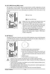
... CMOS values may not be sure to touch the two pins for a few seconds. Turn off . Failure to do so may cause damage to the motherboard. • After system restart, go to BIOS Setup to load factory defaults (select Load Optimized Defaults) or manually configure the BIOS settings (refer to replace...
... CMOS values may not be sure to touch the two pins for a few seconds. Turn off . Failure to do so may cause damage to the motherboard. • After system restart, go to BIOS Setup to load factory defaults (select Load Optimized Defaults) or manually configure the BIOS settings (refer to replace...


