Manual
Page 1
GA-P41T-D3P LGA775 socket motherboard for Intel® Core™ processor family/ Intel® Pentium® processor family/Intel® Celeron® processor family User's Manual Rev. 1301 12ME-P41TD3P-1301R
GA-P41T-D3P LGA775 socket motherboard for Intel® Core™ processor family/ Intel® Pentium® processor family/Intel® Celeron® processor family User's Manual Rev. 1301 12ME-P41TD3P-1301R
Manual
Page 3
...BYTE TECHNOLOGY CO., LTD. Disclaimer Information in this manual is protected by copyright laws and is 1.0. Documentation Classifications In order to assist in the use of this manual may be made by any form or by GIGABYTE without GIGABYTE's prior written permission. For product-related information, ...check on our website at: http://www.gigabyte.com Identifying Your Motherboard Revision The revision number on ...
...BYTE TECHNOLOGY CO., LTD. Disclaimer Information in this manual is protected by copyright laws and is 1.0. Documentation Classifications In order to assist in the use of this manual may be made by any form or by GIGABYTE without GIGABYTE's prior written permission. For product-related information, ...check on our website at: http://www.gigabyte.com Identifying Your Motherboard Revision The revision number on ...
Manual
Page 5
Chapter 3 Drivers Installation 55 3-1 Installing Chipset Drivers 55 3-2 Application Software 56 3-3 Technical Manuals 56 3-4 Contact...57 3-5 System...57 3-6 Download Center 58 3-7 New Utilities...58 Chapter 4 Unique Features 59 4-1 Xpress Recovery2 59 4-2 BIOS Update Utilities 62 4-2-1 Updating the BIOS ...
Chapter 3 Drivers Installation 55 3-1 Installing Chipset Drivers 55 3-2 Application Software 56 3-3 Technical Manuals 56 3-4 Contact...57 3-5 System...57 3-6 Download Center 58 3-7 New Utilities...58 Chapter 4 Unique Features 59 4-1 Xpress Recovery2 59 4-2 BIOS Update Utilities 62 4-2-1 Updating the BIOS ...
Manual
Page 6
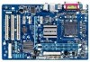
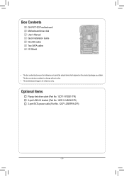
Optional Items Floppy disk drive cable (Part No. 12CF1-1FD001-7*R) 2-port USB 2.0 bracket (Part No. 12CR1-1UB030-5*R) 2-port SATA power cable (Part No. 12CF1-2SERPW-0*R) - 6 - The box contents are for reference only. Box Contents GA-P41T-D3P motherboard Motherboard driver disk User's Manual Quick Installation Guide One IDE cable Two SATA cables I/O Shield • The box contents above are subject to change without notice. • The motherboard image is for reference only and the actual items shall depend on the product package you obtain.
Optional Items Floppy disk drive cable (Part No. 12CF1-1FD001-7*R) 2-port USB 2.0 bracket (Part No. 12CR1-1UB030-5*R) 2-port SATA power cable (Part No. 12CF1-2SERPW-0*R) - 6 - The box contents are for reference only. Box Contents GA-P41T-D3P motherboard Motherboard driver disk User's Manual Quick Installation Guide One IDE cable Two SATA cables I/O Shield • The box contents above are subject to change without notice. • The motherboard image is for reference only and the actual items shall depend on the product package you obtain.
Manual
Page 9
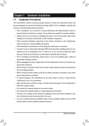
... numerous delicate electronic circuits and components which can lead to damage to the use of electrostatic discharge (ESD). Prior to installation, carefully read the user's manual and follow these procedures: • Prior to installation, do not remove or break motherboard S/N (Serial Number) sticker or warranty sticker provided by unplugging the power...
... numerous delicate electronic circuits and components which can lead to damage to the use of electrostatic discharge (ESD). Prior to installation, carefully read the user's manual and follow these procedures: • Prior to installation, do not remove or break motherboard S/N (Serial Number) sticker or warranty sticker provided by unplugging the power...
Manual
Page 15
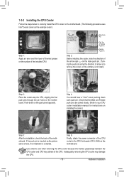
... pins through the pin holes on the motherboard. Check that the Male and Female push pins are joined closely. (Refer to your CPU cooler installation manual for instructions on the surface of arrow is to the CPU. Direction of the Arrow Sign on the Male Push Pin Male Push Pin The...
... pins through the pin holes on the motherboard. Check that the Male and Female push pins are joined closely. (Refer to your CPU cooler installation manual for instructions on the surface of arrow is to the CPU. Direction of the Arrow Sign on the Male Push Pin Male Push Pin The...
Manual
Page 18
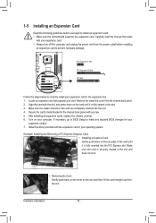
... card straight out from the chassis back panel. 2. Secure the card's metal bracket to make any required BIOS changes for your card. Carefully read the manual that supports your expansion card(s). 7. If necessary, go to BIOS Setup to the chassis back panel with the slot, and press down on your expansion...
... card straight out from the chassis back panel. 2. Secure the card's metal bracket to make any required BIOS changes for your card. Carefully read the manual that supports your expansion card(s). 7. If necessary, go to BIOS Setup to the chassis back panel with the slot, and press down on your expansion...
Manual
Page 27
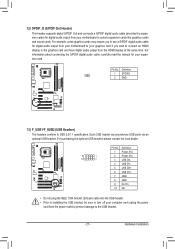
... digital audio output from the power outlet to prevent damage to USB 2.0/1.1 specification. For information about connecting the S/PDIF digital audio cable, carefully read the manual for your computer and unplug the power cord from the HDMI display at the same time.
... digital audio output from the power outlet to prevent damage to USB 2.0/1.1 specification. For information about connecting the S/PDIF digital audio cable, carefully read the manual for your computer and unplug the power cord from the HDMI display at the same time.
Manual
Page 28
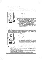
... accurate or may cause damage to the motherboard. • After system restart, go to BIOS Setup to load factory defaults (select Load Optimized Defaults) or manually configure the BIOS settings (refer to Chapter 2, "BIOS Setup," for BIOS configurations). 15) BAT (Battery) The battery provides power to factory defaults. You may clear...
... accurate or may cause damage to the motherboard. • After system restart, go to BIOS Setup to load factory defaults (select Load Optimized Defaults) or manually configure the BIOS settings (refer to Chapter 2, "BIOS Setup," for BIOS configurations). 15) BAT (Battery) The battery provides power to factory defaults. You may clear...
Manual
Page 34
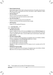
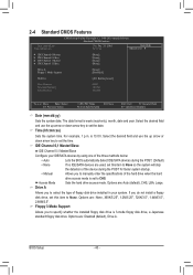
...set in accordance with the CPU specifications. For a 1333 MHz FSB CPU, set this item to 333 MHz. CPU Clock Ratio (Note) Allows you to manually set this feature. For a 1066 MHz FSB CPU, set the PCIe clock frequency. PCI Express Frequency (Mhz) Allows you to alter the clock ratio ... the board to 1200 MHz. This item is configurable only if the CPU Host Clock Control option is highly recommended that supports this item to manually set the R.G.B. Important: It is enabled. Auto sets the PCIe clock frequency to standard 100 MHz. (Default: Auto) (Note) This item appears only if ...
...set in accordance with the CPU specifications. For a 1333 MHz FSB CPU, set this item to 333 MHz. CPU Clock Ratio (Note) Allows you to manually set this feature. For a 1066 MHz FSB CPU, set the PCIe clock frequency. PCI Express Frequency (Mhz) Allows you to alter the clock ratio ... the board to 1200 MHz. This item is configurable only if the CPU Host Clock Control option is highly recommended that supports this item to manually set the R.G.B. Important: It is enabled. Auto sets the PCIe clock frequency to standard 100 MHz. (Default: Auto) (Note) This item appears only if ...
Manual
Page 35
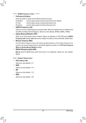
...Setup System Memory Multiplier (SPD) Allows you to fix the chipset frequency at its good performance level. Options are: Auto (default), Manual. >>>>> Standard Timing Control CAS Latency Time Options are dependent on CPU FSB and the (G)MCH Frequency Latch settings. ******** DRAM Performance Control...tRAS Options are : Auto (default), 200MHz, 266MHz, 333MHz. Extreme Lets the system operate at system bootup. DRAM Timing Selectable (SPD) Manual allows all DRAM timing control items below may differ according to be configurable. tRCD Options are : Auto (default), 1~15. tRP Options...
...Setup System Memory Multiplier (SPD) Allows you to fix the chipset frequency at its good performance level. Options are: Auto (default), Manual. >>>>> Standard Timing Control CAS Latency Time Options are dependent on CPU FSB and the (G)MCH Frequency Latch settings. ******** DRAM Performance Control...tRAS Options are : Auto (default), 200MHz, 266MHz, 333MHz. Extreme Lets the system operate at system bootup. DRAM Timing Selectable (SPD) Manual allows all DRAM timing control items below may differ according to be configurable. tRCD Options are : Auto (default), 1~15. tRP Options...
Manual
Page 40
... 0,1 Master/Slave IDE Channel 0,1 Master/Slave Configure your system. Allows you do not install a floppy disk drive, set to manually enter the specifications of the three methods below: • Auto • None Manual Access Mode Drive A Lets the BIOS automatically detect IDE/SATA devices during the POST for faster system startup. If...
... 0,1 Master/Slave IDE Channel 0,1 Master/Slave Configure your system. Allows you do not install a floppy disk drive, set to manually enter the specifications of the three methods below: • Auto • None Manual Access Mode Drive A Lets the BIOS automatically detect IDE/SATA devices during the POST for faster system startup. If...
Manual
Page 45
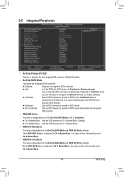
... to Combined. PATA IDE Set to This item is configurable only if the On-Chip SATA Mode is automatically configured to Combined mode, you can manually re-configure it to Enhanced mode as needed. (Default) Combined Sets all SATA devices to Ch. 1 Master/Slave. - 45 - Auto Lets the BIOS set to...
... to Combined. PATA IDE Set to This item is configurable only if the On-Chip SATA Mode is automatically configured to Combined mode, you can manually re-configure it to Enhanced mode as needed. (Default) Combined Sets all SATA devices to Ch. 1 Master/Slave. - 45 - Auto Lets the BIOS set to...
Manual
Page 55
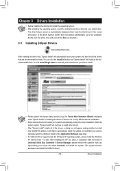
Or click Install Single Items to manually select the drivers you want to manually select the utilities to install on the Application Software page later. • For USB 2.0 driver support under the Windows XP operating system, please install the ... system, insert the motherboard driver disk into your system and then list all of the drivers, a dialog box will appear asking whether to install new GIGABYTE utilities. After the system restart, "Xpress Install" will continue to install other drivers. • After "Xpress Install" installs all the drivers that are recommended to...
Or click Install Single Items to manually select the drivers you want to manually select the utilities to install on the Application Software page later. • For USB 2.0 driver support under the Windows XP operating system, please install the ... system, insert the motherboard driver disk into your system and then list all of the drivers, a dialog box will appear asking whether to install new GIGABYTE utilities. After the system restart, "Xpress Install" will continue to install other drivers. • After "Xpress Install" installs all the drivers that are recommended to...
Manual
Page 56
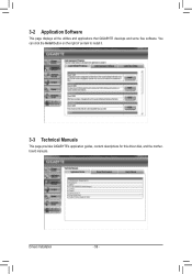
You can click the Install button on the right of an item to install it. 3-3 Technical Manuals This page provides GIGABYTE's application guides, content descriptions for this driver disk, and the motherboard manuals. 3-2 Application Software This page displays all the utilities and applications that GIGABYTE develops and some free software. Drivers Installation - 56 -
You can click the Install button on the right of an item to install it. 3-3 Technical Manuals This page provides GIGABYTE's application guides, content descriptions for this driver disk, and the motherboard manuals. 3-2 Application Software This page displays all the utilities and applications that GIGABYTE develops and some free software. Drivers Installation - 56 -
Manual
Page 62
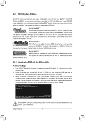
... 62 - Motherboards that matches your motherboard model. 2. With Q-Flash you to access Q-Flash. GIGABYTE Q-Flash and @BIOS are easy-to ensure normal system operation. Normally, the system works on ... like MS-DOS or Window first. What is potentially risky, please do it with the Q-Flash Utility A. P41T-D3P E4c . . . . : BIOS Setup : XpressRecovery2 : Boot Menu : Qflash 12/17/2010-G41-ICH7...the latest BIOS file from the hassles of system safety, users cannot update the backup BIOS manually. Before You Begin 1. Restart the system. Note: You can update the system BIOS ...
... 62 - Motherboards that matches your motherboard model. 2. With Q-Flash you to access Q-Flash. GIGABYTE Q-Flash and @BIOS are easy-to ensure normal system operation. Normally, the system works on ... like MS-DOS or Window first. What is potentially risky, please do it with the Q-Flash Utility A. P41T-D3P E4c . . . . : BIOS Setup : XpressRecovery2 : Boot Menu : Qflash 12/17/2010-G41-ICH7...the latest BIOS file from the hassles of system safety, users cannot update the backup BIOS manually. Before You Begin 1. Restart the system. Note: You can update the system BIOS ...
Manual
Page 65
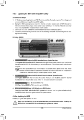
... after updating the BIOS. During the BIOS update process, ensure the Internet connection is unable to save the BIOS update file obtained from GIGABYTE's website and follow the instructions in a corrupted BIOS or a system that is stable and do NOT interrupt the Internet connection (for.... 3. 4-2-2 Updating the BIOS with an incorrect BIOS file could cause your motherboard model. Follow the on the @BIOS server site, please manually download the BIOS update file from the Internet or through other source. C. Updating the BIOS with the @BIOS Utility A. Unique Features In Windows...
... after updating the BIOS. During the BIOS update process, ensure the Internet connection is unable to save the BIOS update file obtained from GIGABYTE's website and follow the instructions in a corrupted BIOS or a system that is stable and do NOT interrupt the Internet connection (for.... 3. 4-2-2 Updating the BIOS with an incorrect BIOS file could cause your motherboard model. Follow the on the @BIOS server site, please manually download the BIOS update file from the Internet or through other source. C. Updating the BIOS with the @BIOS Utility A. Unique Features In Windows...
Manual
Page 71
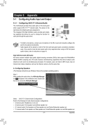
... instructions use Windows Vista as the example operating system.) Step 1: After installing the audio driver, the HD Audio Manager icon will appear in jack and manually configure the jack for each jack through the audio driver. all at the same time. Appendix Double-click the icon to access the HD Audio...
... instructions use Windows Vista as the example operating system.) Step 1: After installing the audio driver, the HD Audio Manager icon will appear in jack and manually configure the jack for each jack through the audio driver. all at the same time. Appendix Double-click the icon to access the HD Audio...


