Manual
Page 4
... ...6 GA-P35-S3G Motherboard Layout 7 Block Diagram ...8 Chapter 1 Hardware Installation 9 1-1 Installation Precautions 9 1-2 Product Specifications 10 1-3 Installing the CPU and CPU Cooler 13 1-3-1 Installing the CPU 13 1-3-2 Installing the CPU Cooler 15 1-4 Installing the Memory 16 1-4-1 Dual Channel Memory Configuration 16 1-4-2 Installing a Memory 17 1-5 Installing an Expansion Card 18 1-6 Back Panel Connectors 19 1-7 Internal Connectors 20 Chapter 2 BIOS Setup 29 2-1 Startup Screen 30 2-2 The Main Menu 31 2-3 Standard CMOS Features 33 2-4 Advanced BIOS Features...
... ...6 GA-P35-S3G Motherboard Layout 7 Block Diagram ...8 Chapter 1 Hardware Installation 9 1-1 Installation Precautions 9 1-2 Product Specifications 10 1-3 Installing the CPU and CPU Cooler 13 1-3-1 Installing the CPU 13 1-3-2 Installing the CPU Cooler 15 1-4 Installing the Memory 16 1-4-1 Dual Channel Memory Configuration 16 1-4-2 Installing a Memory 17 1-5 Installing an Expansion Card 18 1-6 Back Panel Connectors 19 1-7 Internal Connectors 20 Chapter 2 BIOS Setup 29 2-1 Startup Screen 30 2-2 The Main Menu 31 2-3 Standard CMOS Features 33 2-4 Advanced BIOS Features...
Manual
Page 10
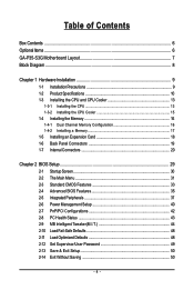
...; 1 x PCI Express x16 slot Š 1 x PCI Express x1 slot Š 5 x PCI slots Š South Bridge: - 4 x SATA 3Gb/s connectors (SATAII0, SATAII1, SATAII4, SATAII5) supporting up to 4 SATA 3Gb/s devices (Note 2) Š JMicron 368 chip: - 1 x IDE connector supporting ATA-133/100/66/33 and up to 2 IDE devices Š iTE IT8718 chip: - 1 x floppy disk drive connector supporting up to 1 floppy disk drive Š Integrated in the South Bridge Š Up to 12 USB 2.0/1.1 ports (6 on the back panel, 6 via the USB brackets connected to the internal USB headers) GA-P35-S3G Motherboard...
...; 1 x PCI Express x16 slot Š 1 x PCI Express x1 slot Š 5 x PCI slots Š South Bridge: - 4 x SATA 3Gb/s connectors (SATAII0, SATAII1, SATAII4, SATAII5) supporting up to 4 SATA 3Gb/s devices (Note 2) Š JMicron 368 chip: - 1 x IDE connector supporting ATA-133/100/66/33 and up to 2 IDE devices Š iTE IT8718 chip: - 1 x floppy disk drive connector supporting up to 1 floppy disk drive Š Integrated in the South Bridge Š Up to 12 USB 2.0/1.1 ports (6 on the back panel, 6 via the USB brackets connected to the internal USB headers) GA-P35-S3G Motherboard...
Manual
Page 12
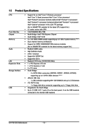
... physical memory is installed, the actual memory size displayed will be less than 4 GB. (Note 2) To enable hot plug capability for the SATA connectors (SATAII0, SATAII1, SATAII4, SATAII5) controlled by the ICH9 South Bridge, you must install Windows Vista (on ICH9, hot plug is supported in Windows Vista only) and configure the SATA connectors for AHCI mode. (Refer to Chapter 2, "BIOS Setup," "Integrated Peripherals," for details on enabling AHCI.) (Note 3) Whether the CPU fan speed control function is supported...
... physical memory is installed, the actual memory size displayed will be less than 4 GB. (Note 2) To enable hot plug capability for the SATA connectors (SATAII0, SATAII1, SATAII4, SATAII5) controlled by the ICH9 South Bridge, you must install Windows Vista (on ICH9, hot plug is supported in Windows Vista only) and configure the SATA connectors for AHCI mode. (Refer to Chapter 2, "BIOS Setup," "Integrated Peripherals," for details on enabling AHCI.) (Note 3) Whether the CPU fan speed control function is supported...
Manual
Page 16
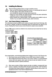
... installed in Dual Channel mode. 1. When memory modules of different capacity and chips are divided into two channels and each channel has two memory sockets as following: Channel 0: DDRII1, DDRII2 Channel 1: DDRII3, DDRII4 Dual Channel Memory Configurations Table DDRII1 DDRII2 DDRII3 Two Modules DS/SS - - DS/SS - - Intel® Flex Memory Technology offers greater flexibility to upgrade by allowing different memory sizes to prevent hardware damage. • Memory modules have a foolproof design. GA-P35-S3G Motherboard...
... installed in Dual Channel mode. 1. When memory modules of different capacity and chips are divided into two channels and each channel has two memory sockets as following: Channel 0: DDRII1, DDRII2 Channel 1: DDRII3, DDRII4 Dual Channel Memory Configurations Table DDRII1 DDRII2 DDRII3 Two Modules DS/SS - - DS/SS - - Intel® Flex Memory Technology offers greater flexibility to upgrade by allowing different memory sizes to prevent hardware damage. • Memory modules have a foolproof design. GA-P35-S3G Motherboard...
Manual
Page 18
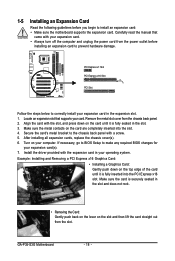
... expansion card. After installing all expansion cards, replace the chassis cover(s). 6. PCI Express x1 Slot PCI Express x16 Slot PCI Slot Follow the steps below to correctly install your operating system. Install the driver provided with your computer. GA-P35-S3G Motherboard - 18 - Carefully read the manual that supports your expansion card(s). 7. Align the card with a screw. 5. Turn on the slot and then lift the card straight out from the slot. Secure the card's metal bracket to the chassis back panel...
... expansion card. After installing all expansion cards, replace the chassis cover(s). 6. PCI Express x1 Slot PCI Express x16 Slot PCI Slot Follow the steps below to correctly install your operating system. Install the driver provided with your computer. GA-P35-S3G Motherboard - 18 - Carefully read the manual that supports your expansion card(s). 7. Align the card with a screw. 5. Turn on the slot and then lift the card straight out from the slot. Secure the card's metal bracket to the chassis back panel...

Manual
Page 22
... the use of floppy disk drives supported are designed with fan speed control design. Do not place a jumper cap on the headers. 6) FDD (Floppy Disk Drive Connector) This connector is the ground wire. For optimum heat dissipation, it in damage to prevent your CPU and system from overheating. The pin 1 of the cable is recommended that a system fan be sure to locate pin 1 of different color. 33 1 34 2 GA-P35-S3G Motherboard - 22 - Each fan header supplies a +12V power voltage and...
... the use of floppy disk drives supported are designed with fan speed control design. Do not place a jumper cap on the headers. 6) FDD (Floppy Disk Drive Connector) This connector is the ground wire. For optimum heat dissipation, it in damage to prevent your CPU and system from overheating. The pin 1 of the cable is recommended that a system fan be sure to locate pin 1 of different color. 33 1 34 2 GA-P35-S3G Motherboard - 22 - Each fan header supplies a +12V power voltage and...
Manual
Page 24
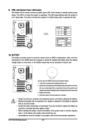
... battery from the battery holder and wait for 5 seconds.) 3. You may be used to connect a system power LED on when the system is in the power cord and restart your computer and unplug the power cord before replacing the battery. • Replace the battery with local environmental regulations. The LED is off when the system is operating. 9) PWR_LED (System Power LED Header) This header can be lost. GA-P35-S3G Motherboard...
... battery from the battery holder and wait for 5 seconds.) 3. You may be used to connect a system power LED on when the system is in the power cord and restart your computer and unplug the power cord before replacing the battery. • Replace the battery with local environmental regulations. The LED is off when the system is operating. 9) PWR_LED (System Power LED Header) This header can be lost. GA-P35-S3G Motherboard...
Manual
Page 26
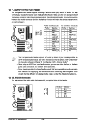
... 4 CD-R GA-P35-S3G Motherboard - 26 - 12) F_AUDIO (Front Panel Audio Header) The front panel audio header supports Intel High Definition audio (HD) and AC'97 audio. If your chassis provides an AC'97 front panel audio module, refer to the instructions on each wire instead of the motherboard header. You may connect the audio cable that came with your chassis front panel audio module to activate AC'97 functioninality via the audio software in Chapter 5, "Configuring 2/4/5.1-Channel Audio." • When using an...
... 4 CD-R GA-P35-S3G Motherboard - 26 - 12) F_AUDIO (Front Panel Audio Header) The front panel audio header supports Intel High Definition audio (HD) and AC'97 audio. If your chassis provides an AC'97 front panel audio module, refer to the instructions on each wire instead of the motherboard header. You may connect the audio cable that came with your chassis front panel audio module to activate AC'97 functioninality via the audio software in Chapter 5, "Configuring 2/4/5.1-Channel Audio." • When using an...

Manual
Page 28
... temporarily short the two pins or use a metal object like a screwdriver to Chapter 2, "BIOS Setup," for a few seconds. This function requires a chassis with chassis intrusion detection design. Pin No. Definition 1 Signal 1 2 GND 17) CLR_CMOS (Clearing CMOS Jumper) Use this jumper to factory defaults. GA-P35-S3G Motherboard - 28 - Failure to do so may cause damage to the motherboard. • After system restart, go to BIOS Setup to load factory defaults (select Load Optimized Defaults) or manually configure the BIOS settings...
... temporarily short the two pins or use a metal object like a screwdriver to Chapter 2, "BIOS Setup," for a few seconds. This function requires a chassis with chassis intrusion detection design. Pin No. Definition 1 Signal 1 2 GND 17) CLR_CMOS (Clearing CMOS Jumper) Use this jumper to factory defaults. GA-P35-S3G Motherboard - 28 - Failure to do so may cause damage to the motherboard. • After system restart, go to BIOS Setup to load factory defaults (select Load Optimized Defaults) or manually configure the BIOS settings...

Manual
Page 32
... devices, such as IDE, SATA, USB, integrated audio, and integrated LAN, etc. „ Power Management Setup Use this menu to configure all the power-saving functions. „ PnP/PCI Configurations Use this menu to configure the system's PCI & PnP resources. „ PC Health Status Use this menu to see information about autodetected system/CPU temperature, system voltage and fan speed, etc. „ MB Intelligent Tweaker(M.I.T.) Use this task.) GA-P35-S3G Motherboard - 32 - An user password only allows you to view the BIOS settings...
... devices, such as IDE, SATA, USB, integrated audio, and integrated LAN, etc. „ Power Management Setup Use this menu to configure all the power-saving functions. „ PnP/PCI Configurations Use this menu to configure the system's PCI & PnP resources. „ PC Health Status Use this menu to see information about autodetected system/CPU temperature, system voltage and fan speed, etc. „ MB Intelligent Tweaker(M.I.T.) Use this task.) GA-P35-S3G Motherboard - 32 - An user password only allows you to view the BIOS settings...

Manual
Page 33
... IDE/SATA devices are used , set to None so the system will skip the detection of the IDE/SATA device on this item to CHS. BIOS Setup For example, 1 p.m. is week (read-only), month, date and year. IDE Channel 0/1 Master IDE HDD Auto-Detection Press to autodetect the parameters of the device during the POST. (Default) If no IDE/SATA devices are used , set this item to manually enter the specifications of the IDE/SATA device on this channel. Sets the hard drive access mode. Options...
... IDE/SATA devices are used , set to None so the system will skip the detection of the IDE/SATA device on this item to CHS. BIOS Setup For example, 1 p.m. is week (read-only), month, date and year. IDE Channel 0/1 Master IDE HDD Auto-Detection Press to autodetect the parameters of the device during the POST. (Default) If no IDE/SATA devices are used , set this item to manually enter the specifications of the IDE/SATA device on this channel. Sets the hard drive access mode. Options...

Manual
Page 35
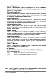
..., Hard Disk, CDROM, ZIP, USB-FDD, USB-ZIP, USB-CDROM, USB-HDD, Legacy LAN, Disabled. HDD S.M.A.R.T. For more information about Intel CPUs' unique features, please visit Intel's website. - 35 - Capability Limit CPUID Max. Press to 3 (Note) No-Execute Memory Protect (Note) CPU Enhanced Halt (C1E) (Note) CPU Thermal Monitor 2(TM2) (Note) CPU EIST Function (Note) Virtualization Technology (Note) Full Screen LOGO Show Init Display First [Press Enter] [Floppy] [Hard Disk] [CDROM] [Setup] [Disabled] [Disabled] [Enabled] [Enabled] [Enabled] [Enabled] [Enabled] [Enabled] [PCI] Item Help Menu...
..., Hard Disk, CDROM, ZIP, USB-FDD, USB-ZIP, USB-CDROM, USB-HDD, Legacy LAN, Disabled. HDD S.M.A.R.T. For more information about Intel CPUs' unique features, please visit Intel's website. - 35 - Capability Limit CPUID Max. Press to 3 (Note) No-Execute Memory Protect (Note) CPU Enhanced Halt (C1E) (Note) CPU Thermal Monitor 2(TM2) (Note) CPU EIST Function (Note) Virtualization Technology (Note) Full Screen LOGO Show Init Display First [Press Enter] [Floppy] [Hard Disk] [CDROM] [Setup] [Disabled] [Disabled] [Enabled] [Enabled] [Enabled] [Enabled] [Enabled] [Enabled] [PCI] Item Help Menu...
Manual
Page 36
Set this item to Disabled for the computer, reducing exposure to display the GIGABYTE Logo at system startup. Disabled displays normal POST message. (Default: Enabled) Init Display First Specifies the first initiation of the monitor display from the installed PCI graphics card or the PCI Express graphics card. GA-P35-S3G Motherboard - 36 - Limit CPUID Max. Virtualization enhanced by Intel® Virtualization Technology will allow a platform to decrease power consumption. (Default: Enabled) CPU Thermal Monitor 2 (TM2) (Note) Enables or disables Intel® CPU Thermal Monitor (...
Set this item to Disabled for the computer, reducing exposure to display the GIGABYTE Logo at system startup. Disabled displays normal POST message. (Default: Enabled) Init Display First Specifies the first initiation of the monitor display from the installed PCI graphics card or the PCI Express graphics card. GA-P35-S3G Motherboard - 36 - Limit CPUID Max. Virtualization enhanced by Intel® Virtualization Technology will allow a platform to decrease power consumption. (Default: Enabled) CPU Thermal Monitor 2 (TM2) (Note) Enables or disables Intel® CPU Thermal Monitor (...

Manual
Page 37
... controllers use dedicated IRQs that allows the storage driver to operate in the Intel ICH9 Southbridge. BIOS Setup SATA Port0-3 Native Mode (Intel ICH9 Southbridge) Specifies the operating mode of the USB functionalities below. 2-5 Integrated Peripherals CMOS Setup Utility-Copyright (C) 1984-2007 Award Software Integrated Peripherals SATA AHCI Mode SATA Port0-3 Native Mode USB Controller USB 2.0 Controller USB Keyboard Support USB Mouse Support Legacy USB storage detect Azalia Codec Onboard H/W LAN ` SMART LAN Onboard LAN Boot ROM Onboard IDE Controller Onboard Serial Port 1 Onboard...
... controllers use dedicated IRQs that allows the storage driver to operate in the Intel ICH9 Southbridge. BIOS Setup SATA Port0-3 Native Mode (Intel ICH9 Southbridge) Specifies the operating mode of the USB functionalities below. 2-5 Integrated Peripherals CMOS Setup Utility-Copyright (C) 1984-2007 Award Software Integrated Peripherals SATA AHCI Mode SATA Port0-3 Native Mode USB Controller USB 2.0 Controller USB Keyboard Support USB Mouse Support Legacy USB storage detect Azalia Codec Onboard H/W LAN ` SMART LAN Onboard LAN Boot ROM Onboard IDE Controller Onboard Serial Port 1 Onboard...

Manual
Page 38
... flash drives and USB hard drives during the POST. (Default: Enabled) Azalia Codec Enables or disables the onboard audio function. (Default: Auto) If you wish to install a 3rd party add-in network card instead of using the onboard audio, set this item to Disabled. Link Detected --> 100Mbps Cable Length= 30m Link Detected Cable Length Displays transmission speed Displays the approximate length of the attached LAN cable. SMART LAN (LAN Cable Diagnostic Function) CMOS Setup Utility-Copyright (C) 1984-2007 Award Software SMART LAN Start detecting at a speed of 10/100Mbps in MS-DOS mode...
... flash drives and USB hard drives during the POST. (Default: Enabled) Azalia Codec Enables or disables the onboard audio function. (Default: Auto) If you wish to install a 3rd party add-in network card instead of using the onboard audio, set this item to Disabled. Link Detected --> 100Mbps Cable Length= 30m Link Detected Cable Length Displays transmission speed Displays the approximate length of the attached LAN cable. SMART LAN (LAN Cable Diagnostic Function) CMOS Setup Utility-Copyright (C) 1984-2007 Award Software SMART LAN Start detecting at a speed of 10/100Mbps in MS-DOS mode...

Manual
Page 39
..., Disabled. Onboard LAN Boot ROM Allows you to decide whether to the fault or short. Onboard Parallel Port Enables or disables the onboard parallel port (LPT) and specifies its base I /O address and corresponding interrupt. Options are : SPP (Standard Parallel Port)(default), EPP (Enhanced Parallel Port), ECP (Extended Capabilities Port), ECP+EPP. - 39 - Parallel Port Mode Selects an operating mode for the onboard parallel (LPT) port. If a cable problem occurs on Pair 1-2. When a Cable Problem Occurs... BIOS Setup Note...
..., Disabled. Onboard LAN Boot ROM Allows you to decide whether to the fault or short. Onboard Parallel Port Enables or disables the onboard parallel port (LPT) and specifies its base I /O address and corresponding interrupt. Options are : SPP (Standard Parallel Port)(default), EPP (Enhanced Parallel Port), ECP (Extended Capabilities Port), ECP+EPP. - 39 - Parallel Port Mode Selects an operating mode for the onboard parallel (LPT) port. If a cable problem occurs on Pair 1-2. When a Cable Problem Occurs... BIOS Setup Note...

Manual
Page 43
... chassis intrusion status. Current Voltage(V) Vcore/DDR18V/+3.3V/+12V Displays the current system voltages. BIOS Setup 2-8 PC Health Status CMOS Setup Utility-Copyright (C) 1984-2007 Award Software PC Health Status Reset Case Open Status Case Opened Vcore DDR18V +3.3V +12V Current System Temperature Current CPU Temperature Current CPU FAN Speed Current SYSTEM FAN2 Speed Current POWER FAN Speed Current SYSTEM FAN1 Speed CPU Warning Temperature CPU FAN Fail Warning SYSTEM FAN2 Fail Warning POWER FAN Fail Warning SYSTEM FAN1 Fail Warning CPU Smart FAN Control [Disabled...
... chassis intrusion status. Current Voltage(V) Vcore/DDR18V/+3.3V/+12V Displays the current system voltages. BIOS Setup 2-8 PC Health Status CMOS Setup Utility-Copyright (C) 1984-2007 Award Software PC Health Status Reset Case Open Status Case Opened Vcore DDR18V +3.3V +12V Current System Temperature Current CPU Temperature Current CPU FAN Speed Current SYSTEM FAN2 Speed Current POWER FAN Speed Current SYSTEM FAN1 Speed CPU Warning Temperature CPU FAN Fail Warning SYSTEM FAN2 Fail Warning POWER FAN Fail Warning SYSTEM FAN1 Fail Warning CPU Smart FAN Control [Disabled...

Manual
Page 45
... the memory frequency that supports this item to manually set the CPU host frequency. CPU Frequency Displays the CPU frequency. PCI Express Frequency (Mhz) Allows you to the CPU Host Frequency (Mhz) and System Memory Multiplier settings. The adjustable range is enabled. System Memory Multiplier Allows you to 333 MHz. BIOS Setup Auto allows the BIOS to automatically set this feature. - 45 - Enabled will allow for automated system reboot, or clear the CMOS values to reset the board to default values. (Default: Disabled) CPU Host Frequency...
... the memory frequency that supports this item to manually set the CPU host frequency. CPU Frequency Displays the CPU frequency. PCI Express Frequency (Mhz) Allows you to the CPU Host Frequency (Mhz) and System Memory Multiplier settings. The adjustable range is enabled. System Memory Multiplier Allows you to 333 MHz. BIOS Setup Auto allows the BIOS to automatically set this feature. - 45 - Enabled will allow for automated system reboot, or clear the CMOS values to reset the board to default values. (Default: Disabled) CPU Host Frequency...

Manual
Page 50
... item and press the key. Press or to return to the CMOS and exits the BIOS Setup program. GA-P35-S3G Motherboard - 50 - Press or to return to the BIOS Setup Main Menu. 2-14 Exit Without Saving CMOS Setup Utility-Copyright (C) 1984-2007 Award Software ` Standard CMOS Features Load Fail-Safe Defaults ` Advanced BIOS Features Load Optimized Defaults ` Integrated Peripherals Set Supervisor Password ` Power Management Setup Quit Without Saving (SYe/tNU)?seNr Password ` PnP/PCI Configurations Save & Exit Setup ` PC Health Status...
... item and press the key. Press or to return to the CMOS and exits the BIOS Setup program. GA-P35-S3G Motherboard - 50 - Press or to return to the BIOS Setup Main Menu. 2-14 Exit Without Saving CMOS Setup Utility-Copyright (C) 1984-2007 Award Software ` Standard CMOS Features Load Fail-Safe Defaults ` Advanced BIOS Features Load Optimized Defaults ` Integrated Peripherals Set Supervisor Password ` Power Management Setup Quit Without Saving (SYe/tNU)?seNr Password ` PnP/PCI Configurations Save & Exit Setup ` PC Health Status...

Manual
Page 75
... the Main Menu, press + to the Support\Motherboard\FAQ page on the CLR_CMOS jumper in Chapter 1. Q: How do the beeps emitted during the POST. Plug in the BIOS Setup program. Turn off your computer. 5. A: The following Award BIOS beep code descriptions may help you identify possible computer problems. (For reference only.) 1 short: System boots successfully 2 short: CMOS setting error 1 long, 1 short: Memory or motherboard error 1 long, 2 short: Monitor or graphics card error 1 long, 3 short: Keyboard error 1 long, 9 short: BIOS ROM error Continuous long beeps...
... the Main Menu, press + to the Support\Motherboard\FAQ page on the CLR_CMOS jumper in Chapter 1. Q: How do the beeps emitted during the POST. Plug in the BIOS Setup program. Turn off your computer. 5. A: The following Award BIOS beep code descriptions may help you identify possible computer problems. (For reference only.) 1 short: System boots successfully 2 short: CMOS setting error 1 long, 1 short: Memory or motherboard error 1 long, 2 short: Monitor or graphics card error 1 long, 3 short: Keyboard error 1 long, 9 short: BIOS ROM error Continuous long beeps...


