Manual
Page 1
GA-P35-DS4 LGA775 socket motherboard for Intel® CoreTM processor family/ Intel® Pentium® processor family/Intel® Celeron® processor family User's Manual Rev. 2003 12ME-P35DS4-2003R
GA-P35-DS4 LGA775 socket motherboard for Intel® CoreTM processor family/ Intel® Pentium® processor family/Intel® Celeron® processor family User's Manual Rev. 2003 12ME-P35DS4-2003R
Manual
Page 6
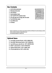
...-1SPDIN-01R) COM port cable (Part No. 12CF1-1CM001-32R) LPT port cable (Part No. 12CF1-1LP001-01R) - 6 - Box Contents GA-P35-DS4 motherboard Motherboard driver disk User's Manual Quick Installation Guide Intel® LGA775 CPU Installation Guide One IDE cable and one floppy disk drive cable Four SATA 3Gb/s cables One SATA bracket...
...-1SPDIN-01R) COM port cable (Part No. 12CF1-1CM001-32R) LPT port cable (Part No. 12CF1-1LP001-01R) - 6 - Box Contents GA-P35-DS4 motherboard Motherboard driver disk User's Manual Quick Installation Guide Intel® LGA775 CPU Installation Guide One IDE cable and one floppy disk drive cable Four SATA 3Gb/s cables One SATA bracket...

Manual
Page 8
... PCIe CLK (100 MHz) LAN RJ45 x1 x1 x1 Switch RTL8111B x1 PCI Express Bus 2 SATA 3Gb/s ATA-133/100/66/ 33 IDE Channel GIGABYTE SATA2 PCI Bus TSB43AB23 3 IEEE 1394a LGA775 Processor CPU CLK+/- (400 (O.C.)/333/ 266/200 MHz) Host Interface DDR2 1200 (O.C.)/1066/ 800/667 MHz... Intel® P35 Dual Channel Memory MCH CLK (333/266/200 MHz) Intel® ICH9R CODEC Dual BIOS 6 SATA 3Gb/s 12 USB Ports IT8718 Floppy LPT Port COM Port PS/2 KB/Mouse 2 PCI...
... PCIe CLK (100 MHz) LAN RJ45 x1 x1 x1 Switch RTL8111B x1 PCI Express Bus 2 SATA 3Gb/s ATA-133/100/66/ 33 IDE Channel GIGABYTE SATA2 PCI Bus TSB43AB23 3 IEEE 1394a LGA775 Processor CPU CLK+/- (400 (O.C.)/333/ 266/200 MHz) Host Interface DDR2 1200 (O.C.)/1066/ 800/667 MHz... Intel® P35 Dual Channel Memory MCH CLK (333/266/200 MHz) Intel® ICH9R CODEC Dual BIOS 6 SATA 3Gb/s 12 USB Ports IT8718 Floppy LPT Port COM Port PS/2 KB/Mouse 2 PCI...
Manual
Page 10
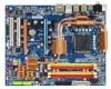
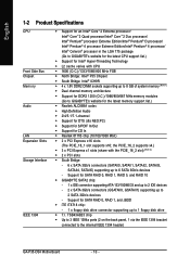
... PCI Express x1 slots (share with CPU Š 1600 (O.C.)/1333/1066/800 MHz FSB Š North Bridge: Intel® P35 Chipset Š South Bridge: Intel® ICH9R Š 4 x 1.8V DDR2 DIMM sockets supporting up to 8 GB of system memory (Note ...1) Š Dual channel memory architecture Š Support for DDR2 1200 (O.C.)/1066/800/667 MHz memory modules (Go to GIGABYTE... the IEEE 1394 bracket connected to the internal IEEE 1394 header) GA-P35-DS4 Motherboard - 10 -
... PCI Express x1 slots (share with CPU Š 1600 (O.C.)/1333/1066/800 MHz FSB Š North Bridge: Intel® P35 Chipset Š South Bridge: Intel® ICH9R Š 4 x 1.8V DDR2 DIMM sockets supporting up to 8 GB of system memory (Note ...1) Š Dual channel memory architecture Š Support for DDR2 1200 (O.C.)/1066/800/667 MHz memory modules (Go to GIGABYTE... the IEEE 1394 bracket connected to the internal IEEE 1394 header) GA-P35-DS4 Motherboard - 10 -

Manual
Page 12
... differ by motherboard model. (Note 4) The adjustable CPU voltage range depends on the CPU being used. (Note 5) Due to chipset limitation, Intel ICH9R RAID driver does not support Windows 2000 operating system. Increase PCIe voltage by 0.05V to 0.35V with 1 MHz increment Š Support ...Security (OEM version) Š Voltage adjustments in BIOS Setup (CPU/DDR2/PCIe) allow you to 700 MHz with 0.05V increment - Adjust DDR2 frequency - GA-P35-DS4 Motherboard - 12 - Adjust CPU host frequency from 90 MHz to : - Adjust PCI Express x16 frequency from 100 MHz to : - Increase FSB voltage ...
... differ by motherboard model. (Note 4) The adjustable CPU voltage range depends on the CPU being used. (Note 5) Due to chipset limitation, Intel ICH9R RAID driver does not support Windows 2000 operating system. Increase PCIe voltage by 0.05V to 0.35V with 1 MHz increment Š Support ...Security (OEM version) Š Voltage adjustments in BIOS Setup (CPU/DDR2/PCIe) allow you to 700 MHz with 0.05V increment - Adjust DDR2 frequency - GA-P35-DS4 Motherboard - 12 - Adjust CPU host frequency from 90 MHz to : - Adjust PCI Express x16 frequency from 100 MHz to : - Increase FSB voltage ...

Manual
Page 16
... cannot be installed in Dual Channel mode. 1. The four DDR2 memory sockets are unable to GIGABYTE's website for optimum performance. DS/SS - - When enabling Dual Channel mode with two or... four memory modules, it is installed, the BIOS will double the original memory bandwidth. GA-P35-DS4 Motherboard - 16 - If you begin to install the memory: • Make sure that memory of the... motherboard supports the memory. Four Modules DS/SS DS/SS DS/SS DDRII4 - Intel® Flex Memory Technology offers greater flexibility to upgrade by allowing different memory sizes ...
... cannot be installed in Dual Channel mode. 1. The four DDR2 memory sockets are unable to GIGABYTE's website for optimum performance. DS/SS - - When enabling Dual Channel mode with two or... four memory modules, it is installed, the BIOS will double the original memory bandwidth. GA-P35-DS4 Motherboard - 16 - If you begin to install the memory: • Make sure that memory of the... motherboard supports the memory. Four Modules DS/SS DS/SS DS/SS DDRII4 - Intel® Flex Memory Technology offers greater flexibility to upgrade by allowing different memory sizes ...
Manual
Page 24
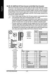
.../Off) GND GND GND -5V +5V +5V +5V (Only for 2x12 pin ATX) GND (Only for 2x4 pin 12V) 7 +12V 8 +12V 12 24 1 13 ATX GA-P35-DS4 Motherboard ATX: Pin No. 1 2 3 4 5 6 7 8 9 10 11 12 Definition Pin No. 3.3V 13 3.3V 14 GND 15 +5V 16 GND 17 +5V 18 GND 19 Power... Good 20 5V SB(stand by the CPU manufacturer when using an Intel Extreme Edition CPU (130W). • To meet expansion requirements, it is recommended that a power supply that does not provide the required power, the result can...
.../Off) GND GND GND -5V +5V +5V +5V (Only for 2x12 pin ATX) GND (Only for 2x4 pin 12V) 7 +12V 8 +12V 12 24 1 13 ATX GA-P35-DS4 Motherboard ATX: Pin No. 1 2 3 4 5 6 7 8 9 10 11 12 Definition Pin No. 3.3V 13 3.3V 14 GND 15 +5V 16 GND 17 +5V 18 GND 19 Power... Good 20 5V SB(stand by the CPU manufacturer when using an Intel Extreme Edition CPU (130W). • To meet expansion requirements, it is recommended that a power supply that does not provide the required power, the result can...

Manual
Page 38
... at system startup, refer to access the Q-Flash utility directly without entering BIOS Setup. To exit Boot Menu, press . Note: The setting in Boot Menu. GA-P35-DS4 Motherboard - 38 - In Boot Menu, use the up hard drive data using the motherboard driver disk, the key can access Boot Menu again to change... as needed. : GQ-Flash Press the key to the instructions on the Full Screen LOGO Show item on BIOS Setup settings. Motherboard Model BIOS Version Intel P35 BIOS for one time only. A.
... at system startup, refer to access the Q-Flash utility directly without entering BIOS Setup. To exit Boot Menu, press . Note: The setting in Boot Menu. GA-P35-DS4 Motherboard - 38 - In Boot Menu, use the up hard drive data using the motherboard driver disk, the key can access Boot Menu again to change... as needed. : GQ-Flash Press the key to the instructions on the Full Screen LOGO Show item on BIOS Setup settings. Motherboard Model BIOS Version Intel P35 BIOS for one time only. A.

Manual
Page 44
... a CPU that supports this feature. GA-P35-DS4 Motherboard - 44 - to 3 (Note) Allows you to determine whether to display the GIGABYTE Logo at system startup. set this item to Disabled for the computer, reducing exposure to decrease power consumption. (Default: Enabled) CPU Thermal Monitor 2 (TM2) (Note) Enables or disables Intel® CPU Thermal Monitor (TM2...
... a CPU that supports this feature. GA-P35-DS4 Motherboard - 44 - to 3 (Note) Allows you to determine whether to display the GIGABYTE Logo at system startup. set this item to Disabled for the computer, reducing exposure to decrease power consumption. (Default: Enabled) CPU Thermal Monitor 2 (TM2) (Note) Enables or disables Intel® CPU Thermal Monitor (TM2...

Manual
Page 52
...Specifies how to control CPU fan speed. A small portion of system memory will be controlled by the Intel Quiet System Technology (QST). Auto Lets BIOS control CPU fan speed. (Default) Intel(R) QST Allows CPU fan speed to run at full speed. Disabled Forces CPU fan to be shared... when Intel® QST is enabled. Auto Lets BIOS autodetect the type of Intel Host Embedded Control Interface (HECI) driver from the motherboard driver disk. Note: The Voltage mode can be set to the CPU temperature. GA-P35-DS4 Motherboard - 52 - Legacy Allows CPU fan...
...Specifies how to control CPU fan speed. A small portion of system memory will be controlled by the Intel Quiet System Technology (QST). Auto Lets BIOS control CPU fan speed. (Default) Intel(R) QST Allows CPU fan speed to run at full speed. Disabled Forces CPU fan to be shared... when Intel® QST is enabled. Auto Lets BIOS autodetect the type of Intel Host Embedded Control Interface (HECI) driver from the motherboard driver disk. Note: The Voltage mode can be set to the CPU temperature. GA-P35-DS4 Motherboard - 52 - Legacy Allows CPU fan...

Manual
Page 66
... Xpress Recovery2 for P35-DS4 F5e . . . . : BIOS Setup : XpressRecovery2 : Boot Menu : Qflash 04/03/2007-P35-ICH9-6A790G0GC-00 Figure 9 C. Award Modular BIOS v6.00PG, An Energy Star Ally Copyright (C) 1984-2007, Award Software, Inc. Boot from CD/DVD: Press any key to startup XpressRecovery2..... Intel P35 BIOS for the ... Recovery2 will automatically create a new partition to enter Xpress Recovery2 later, simply press during the POST (Figure 9). Figure 10 Figure 11 3. Figure 12 GA-P35-DS4 Motherboard Xpress Recovery2 will then begin the backup process (Figure 11).
... Xpress Recovery2 for P35-DS4 F5e . . . . : BIOS Setup : XpressRecovery2 : Boot Menu : Qflash 04/03/2007-P35-ICH9-6A790G0GC-00 Figure 9 C. Award Modular BIOS v6.00PG, An Energy Star Ally Copyright (C) 1984-2007, Award Software, Inc. Boot from CD/DVD: Press any key to startup XpressRecovery2..... Intel P35 BIOS for the ... Recovery2 will automatically create a new partition to enter Xpress Recovery2 later, simply press during the POST (Figure 9). Figure 10 Figure 11 3. Figure 12 GA-P35-DS4 Motherboard Xpress Recovery2 will then begin the backup process (Figure 11).

Manual
Page 68
...GIGABYTE Q-Flash and @BIOS are easy-to-use FAT32/16/12 file system. 3. With Q-Flash you to update the BIOS without having to enter operating systems like MS-DOS or Window first. TM @BIOS allows you from the nearest @BIOS server site and update the BIOS. 4-2-1 Updating the BIOS with caution. GA-P35-DS4....00PG, An Energy Star Ally Copyright (C) 1984-2007, Award Software, Inc. Motherboards that matches your floppy disk, USB flash drive, or hard drive. Intel P35 BIOS for the safety and stability of your computer by either pressing the key during the POST to enter Q-Flash.
...GIGABYTE Q-Flash and @BIOS are easy-to-use FAT32/16/12 file system. 3. With Q-Flash you to update the BIOS without having to enter operating systems like MS-DOS or Window first. TM @BIOS allows you from the nearest @BIOS server site and update the BIOS. 4-2-1 Updating the BIOS with caution. GA-P35-DS4....00PG, An Energy Star Ally Copyright (C) 1984-2007, Award Software, Inc. Motherboards that matches your floppy disk, USB flash drive, or hard drive. Intel P35 BIOS for the safety and stability of your computer by either pressing the key during the POST to enter Q-Flash.

Manual
Page 75
..., refer to "Chapter 1," "Hardware Installation," to identify the SATA controller for the SATA port. (For example, on the GA-P35-DS4 motherboard, the SATAII0, SATAII1, SATAII2, SATAII3, SATAII4 and SATAII5 ports are supported by ICH9R Southbridge.) Then connect the power connector... • An empty formatted floppy disk. • Windows Vista/XP/2000 (Note 3) setup disk. • Motherboard driver disk. 5-1-1 Configuring Intel® ICH9R SATA Controllers A. Appendix English Chapter 5 Appendix 5-1 Configuring SATA Hard Drive(s) To configure SATA hard drive(s), follow the steps below: ...
..., refer to "Chapter 1," "Hardware Installation," to identify the SATA controller for the SATA port. (For example, on the GA-P35-DS4 motherboard, the SATAII0, SATAII1, SATAII2, SATAII3, SATAII4 and SATAII5 ports are supported by ICH9R Southbridge.) Then connect the power connector... • An empty formatted floppy disk. • Windows Vista/XP/2000 (Note 3) setup disk. • Motherboard driver disk. 5-1-1 Configuring Intel® ICH9R SATA Controllers A. Appendix English Chapter 5 Appendix 5-1 Configuring SATA Hard Drive(s) To configure SATA hard drive(s), follow the steps below: ...

Manual
Page 78
There are typical values: RAID0 - 128KB RAID10 - 64KB RAID5 - 64KB [K L ]-Change [TAB]-Next [ESC]-Previous Menu Figure 5 [ENTER]-Select GA-P35-DS4 Motherboard - 78 - All Rights Reversed. [ CREATE VOLUME MENU ] Name : RAID Level : Disks : Strip Size : Capacity : Volume0 RAID0(Stripe...two hard drives are installed, they will be automatically assigned to be included in the RAID array. Intel(R) Matrix Storage Manager option ROM v7.5.0.1014 ICH9R wRAID5 Copyright(C) 2003-07 Intel Corporation. Then, select a RAID level (Figure 4). Mirrors data (redundancy). English Step 3: After ...
There are typical values: RAID0 - 128KB RAID10 - 64KB RAID5 - 64KB [K L ]-Change [TAB]-Next [ESC]-Previous Menu Figure 5 [ENTER]-Select GA-P35-DS4 Motherboard - 78 - All Rights Reversed. [ CREATE VOLUME MENU ] Name : RAID Level : Disks : Strip Size : Capacity : Volume0 RAID0(Stripe...two hard drives are installed, they will be automatically assigned to be included in the RAID array. Intel(R) Matrix Storage Manager option ROM v7.5.0.1014 ICH9R wRAID5 Copyright(C) 2003-07 Intel Corporation. Then, select a RAID level (Figure 4). Mirrors data (redundancy). English Step 3: After ...

Manual
Page 80
... reset the disks to be deleted and press . WARNING: ALL DISK DATA WILL BE DELETED. [K L ]-Select [ESC]-Previous Menu Figure 8 [DEL]-Delete Volume GA-P35-DS4 Motherboard - 80 - In the DELETE VOLUME MENU section, use the up or down arrow key to select the array to non-RAID. Name Volume0... Intel(R) Matrix Storage Manager option ROM v7.5.0.1014 ICH9R wRAID5 Copyright(C) 2003-07 Intel Corporation. English Delete RAID Volume To delete a RAID array, select Delete RAID Volume in MAIN MENU and ...
... reset the disks to be deleted and press . WARNING: ALL DISK DATA WILL BE DELETED. [K L ]-Select [ESC]-Previous Menu Figure 8 [DEL]-Delete Volume GA-P35-DS4 Motherboard - 80 - In the DELETE VOLUME MENU section, use the up or down arrow key to select the array to non-RAID. Name Volume0... Intel(R) Matrix Storage Manager option ROM v7.5.0.1014 ICH9R wRAID5 Copyright(C) 2003-07 Intel Corporation. English Delete RAID Volume To delete a RAID array, select Delete RAID Volume in MAIN MENU and ...

Manual
Page 92
When a screen similar to boot from the Windows Vista setup disk and perform standard OS installation steps. Figure 9 GA-P35-DS4 Motherboard - 92 - Figure 8 Step 2: Specify the location where the driver is saved, such as your system to that only one RAID array exists in your system.) Intel ICH9R SATA controllers: Step 1: Restart your floppy disk (Figure 9). Installing Windows Vista (The procedure below assumes that below appears, select Load Driver. (Figure 8). English B.
When a screen similar to boot from the Windows Vista setup disk and perform standard OS installation steps. Figure 9 GA-P35-DS4 Motherboard - 92 - Figure 8 Step 2: Specify the location where the driver is saved, such as your system to that only one RAID array exists in your system.) Intel ICH9R SATA controllers: Step 1: Restart your floppy disk (Figure 9). Installing Windows Vista (The procedure below assumes that below appears, select Load Driver. (Figure 8). English B.

Manual
Page 96
... user to the right shows the default audio jack assignments. A. Before installing the audio driver, make a telephone call over the Internet, and etc. GA-P35-DS4 Motherboard - 96 - Side Speaker Out Mic In For example, in a 4-channel audio configuration, if a Rear speaker is plugged into the default Center... Out Rear Speaker Out Line In Front Speaker Out jack retasking capability that allow multiple audio streams (in your front panel audio supports Intel HD Audio standard, you can listen to the Mic in or Line in jack and manually configure the jack for Windows. (Note)...
... user to the right shows the default audio jack assignments. A. Before installing the audio driver, make a telephone call over the Internet, and etc. GA-P35-DS4 Motherboard - 96 - Side Speaker Out Mic In For example, in a 4-channel audio configuration, if a Rear speaker is plugged into the default Center... Out Rear Speaker Out Line In Front Speaker Out jack retasking capability that allow multiple audio streams (in your front panel audio supports Intel HD Audio standard, you can listen to the Mic in or Line in jack and manually configure the jack for Windows. (Note)...


