Manual
Page 1
GA-P35-DS3L/ GA-P35-S3L LGA775 socket motherboard for Intel® CoreTM processor family/ Intel® Pentium® processor family/Intel® Celeron® processor family User's Manual Rev. 2001 12ME-P35DS3L-2001R * The WEEE marking on the product indicates this product must not be disposed of with user's other household waste and must be handed over to a designated collection point for the recycling of waste electrical and electronic equipment!! * The WEEE marking applies only in European Union's member states.
GA-P35-DS3L/ GA-P35-S3L LGA775 socket motherboard for Intel® CoreTM processor family/ Intel® Pentium® processor family/Intel® Celeron® processor family User's Manual Rev. 2001 12ME-P35DS3L-2001R * The WEEE marking on the product indicates this product must not be disposed of with user's other household waste and must be handed over to a designated collection point for the recycling of waste electrical and electronic equipment!! * The WEEE marking applies only in European Union's member states.

Manual
Page 2
Motherboard GA-P35-DS3L/GA-P35-S3L Jul. 31, 2007 Motherboard GA-P35-DS3L/GA-P35-S3L Jul. 31, 2007
Motherboard GA-P35-DS3L/GA-P35-S3L Jul. 31, 2007 Motherboard GA-P35-DS3L/GA-P35-S3L Jul. 31, 2007
Manual
Page 3
... CO., LTD. Changes to use of this : "REV: X.X." For product-related information, check on our website at: http://www.gigabyte.com.tw Identifying Your Motherboard Revision The revision number on your motherboard revision before updating motherboard BIOS, drivers, or when looking for technical information. Example: - 3 - No part of this manual may be reproduced, copied...
... CO., LTD. Changes to use of this : "REV: X.X." For product-related information, check on our website at: http://www.gigabyte.com.tw Identifying Your Motherboard Revision The revision number on your motherboard revision before updating motherboard BIOS, drivers, or when looking for technical information. Example: - 3 - No part of this manual may be reproduced, copied...
Manual
Page 4
Table of Contents Box Contents ...6 OptionalItems ...6 GA-P35-DS3L/S3L Motherboard Layout 7 Block Diagram ...8 Chapter 1 Hardware Installation 9 1-1 Installation Precautions 9 1-2 Product Specifications 10 1-3 Installing the CPU and CPU Cooler 13 1-3-1 Installing the CPU 13 1-3-2 Installing the CPU ...
Table of Contents Box Contents ...6 OptionalItems ...6 GA-P35-DS3L/S3L Motherboard Layout 7 Block Diagram ...8 Chapter 1 Hardware Installation 9 1-1 Installation Precautions 9 1-2 Product Specifications 10 1-3 Installing the CPU and CPU Cooler 13 1-3-1 Installing the CPU 13 1-3-2 Installing the CPU ...
Manual
Page 6
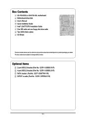
Box Contents GA-P35-DS3L or GA-P35-S3L motherboard Motherboard driver disk User's Manual Quick Installation Guide Intel® LGA775 CPU Installation Guide One IDE cable and one floppy disk drive cable Two SATA 3Gb/s ...
Box Contents GA-P35-DS3L or GA-P35-S3L motherboard Motherboard driver disk User's Manual Quick Installation Guide Intel® LGA775 CPU Installation Guide One IDE cable and one floppy disk drive cable Two SATA 3Gb/s ...

Manual
Page 7
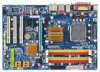
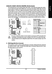
GA-P35-DS3L/S3L Motherboard Layout KB_MS COAXIAL OPTICAL ATX_12V LGA775 CPU_FAN ATX COM LPT DDRII1 GA-P35-DS3L/S3L R_USB SYS_FAN2 USB LAN F_AUDIO AUDIO SYS_FAN1 PCIE_3 RTL8111B PCIE_16 PCIE_1 SPDIF_O CODEC PCIE_2 SPDIF_I PCI1 PCI2 IT8718 PCI3 CD_IN Intel® P35 FDD DDRII3 DDRII4 DDRII2 PWR_FAN Intel® ICH9 BATTERY CLR_CMOS SATAII0 SATAII1 JMicron 368 SATAII4 BIOS SATAII5 IDE1 F_USB3 F_USB2 F_USB1 CI F_PANEL PWR_LED "*" Only the GA-P35-DS3L adopts All-Solid Capacitor design. - 7 -
GA-P35-DS3L/S3L Motherboard Layout KB_MS COAXIAL OPTICAL ATX_12V LGA775 CPU_FAN ATX COM LPT DDRII1 GA-P35-DS3L/S3L R_USB SYS_FAN2 USB LAN F_AUDIO AUDIO SYS_FAN1 PCIE_3 RTL8111B PCIE_16 PCIE_1 SPDIF_O CODEC PCIE_2 SPDIF_I PCI1 PCI2 IT8718 PCI3 CD_IN Intel® P35 FDD DDRII3 DDRII4 DDRII2 PWR_FAN Intel® ICH9 BATTERY CLR_CMOS SATAII0 SATAII1 JMicron 368 SATAII4 BIOS SATAII5 IDE1 F_USB3 F_USB2 F_USB1 CI F_PANEL PWR_LED "*" Only the GA-P35-DS3L adopts All-Solid Capacitor design. - 7 -
Manual
Page 9
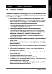
... required for warranty validation. • Always remove the AC power by your hardware components are connected. • To prevent damage to the motherboard, do not allow screws to come in a high-temperature environment. • Turning on the computer power during the installation process can become ...damaged as a result of electrostatic discharge (ESD). Hardware Installation If you are connected tightly and securely. • When handling the motherboard, avoid touching any installation steps or have it on top of an antistatic pad or within the computer casing. • Do not ...
... required for warranty validation. • Always remove the AC power by your hardware components are connected. • To prevent damage to the motherboard, do not allow screws to come in a high-temperature environment. • Turning on the computer power during the installation process can become ...damaged as a result of electrostatic discharge (ESD). Hardware Installation If you are connected tightly and securely. • When handling the motherboard, avoid touching any installation steps or have it on top of an antistatic pad or within the computer casing. • Do not ...
Manual
Page 10
...Intel® Pentium® 4 processor/ Intel® Celeron® processor in the LGA 775 package (Go to GIGABYTE's website for the latest CPU support list.) Š Support for Intel® Hyper-Threading Technology Š L2... 1) Š Dual channel memory architecture Š Support for DDR2 1066/800/667 MHz memory modules (Go to GIGABYTE's website for the latest memory support list.) Š Realtek ALC888 codec Š High Definition Audio Š ...brackets connected to the internal USB headers) "*" Only the GA-P35-DS3L adopts All-Solid Capacitor design. GA-P35-DS3L/S3L Motherboard - 10 -
...Intel® Pentium® 4 processor/ Intel® Celeron® processor in the LGA 775 package (Go to GIGABYTE's website for the latest CPU support list.) Š Support for Intel® Hyper-Threading Technology Š L2... 1) Š Dual channel memory architecture Š Support for DDR2 1066/800/667 MHz memory modules (Go to GIGABYTE's website for the latest memory support list.) Š Realtek ALC888 codec Š High Definition Audio Š ...brackets connected to the internal USB headers) "*" Only the GA-P35-DS3L adopts All-Solid Capacitor design. GA-P35-DS3L/S3L Motherboard - 10 -
Manual
Page 12
... SATA connectors for AHCI mode. (Refer to Chapter 2, "BIOS Setup," "Integrated Peripherals," for details on enabling AHCI.) (Note 3) Available functions in Easytune may differ by motherboard model. GA-P35-DS3L/S3L Motherboard - 12 -
... SATA connectors for AHCI mode. (Refer to Chapter 2, "BIOS Setup," "Integrated Peripherals," for details on enabling AHCI.) (Note 3) Available functions in Easytune may differ by motherboard model. GA-P35-DS3L/S3L Motherboard - 12 -
Manual
Page 13
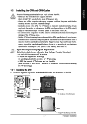
...8226; An operating system that is optimized for instructions on enabling the HT Technology.) 1-3-1 Installing the CPU A. Locate the alignment keys on the motherboard CPU socket and the notches on the CPU Hardware Installation LGA775 CPU Socket Alignment Key LGA 775 CPU Alignment Key Pin One Corner of the... the system bus frequency be inserted if oriented incorrectly. (Or you begin to install the CPU: • Make sure that the motherboard supports the CPU. (Go to GIGABYTE's website for the latest CPU support list.) • Always turn on the computer if the CPU cooler is not recom- It...
...8226; An operating system that is optimized for instructions on enabling the HT Technology.) 1-3-1 Installing the CPU A. Locate the alignment keys on the motherboard CPU socket and the notches on the CPU Hardware Installation LGA775 CPU Socket Alignment Key LGA 775 CPU Alignment Key Pin One Corner of the... the system bus frequency be inserted if oriented incorrectly. (Or you begin to install the CPU: • Make sure that the motherboard supports the CPU. (Go to GIGABYTE's website for the latest CPU support list.) • Always turn on the computer if the CPU cooler is not recom- It...

Manual
Page 14
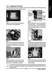
... turn off the computer and unplug the power cord from the power outlet to prevent damage to correctly install the CPU into the motherboard CPU socket. Step 3: Lift the metal load plate on the CPU socket. Step 2: Remove the protective socket cover. GA-P35-DS3L/S3L Motherboard - 14 - Follow the steps below to the CPU.
... turn off the computer and unplug the power cord from the power outlet to prevent damage to correctly install the CPU into the motherboard CPU socket. Step 3: Lift the metal load plate on the CPU socket. Step 2: Remove the protective socket cover. GA-P35-DS3L/S3L Motherboard - 14 - Follow the steps below to the CPU.
Manual
Page 15
... above, the installation is to install.) Step 3: Place the cooler atop the CPU, aligning the four push pins through the pin holes on the motherboard. Step 4: You should hear a "click" when pushing down on the push pins diagonally. If the push pin is inserted as the example cooler... Hardware Installation Step 6: Finally, attach the power connector of arrow is to your CPU cooler installation manual for instructions on the surface of the motherboard. Direction of the Arrow Sign on the Male Push Pin Male Push Pin The Top of Female Push Pin Female Push Pin Step 2: Before ...
... above, the installation is to install.) Step 3: Place the cooler atop the CPU, aligning the four push pins through the pin holes on the motherboard. Step 4: You should hear a "click" when pushing down on the push pins diagonally. If the push pin is inserted as the example cooler... Hardware Installation Step 6: Finally, attach the power connector of arrow is to your CPU cooler installation manual for instructions on the surface of the motherboard. Direction of the Arrow Sign on the Male Push Pin Male Push Pin The Top of Female Push Pin Female Push Pin Step 2: Before ...
Manual
Page 16
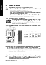
...and chips be populated and remain in Flex Memory Mode will appear during the POST. GA-P35-DS3L/S3L Motherboard - 16 - DS/SS - - Dual Channel mode cannot be used . (Go to GIGABYTE's website for optimum performance. Enabling Dual Channel memory mode will automatically detect the specifications ... unable to install the memory: • Make sure that the motherboard supports the memory. If you begin to insert the memory, switch the direction. 1-4-1 Dual Channel Memory Configuration This motherboard provides four DDR2 memory sockets and supports Dual Channel Technology. After ...
...and chips be populated and remain in Flex Memory Mode will appear during the POST. GA-P35-DS3L/S3L Motherboard - 16 - DS/SS - - Dual Channel mode cannot be used . (Go to GIGABYTE's website for optimum performance. Enabling Dual Channel memory mode will automatically detect the specifications ... unable to install the memory: • Make sure that the motherboard supports the memory. If you begin to insert the memory, switch the direction. 1-4-1 Dual Channel Memory Configuration This motherboard provides four DDR2 memory sockets and supports Dual Channel Technology. After ...
Manual
Page 17
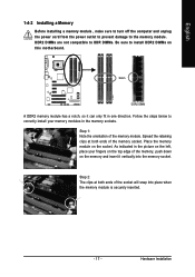
... , make sure to turn off the computer and unplug the power cord from the power outlet to prevent damage to install DDR2 DIMMs on this motherboard. Notch DDR2 DIMM A DDR2 memory module has a notch, so it vertically into place when the memory module is securely inserted. - 17 - DDR2 DIMMs are not...
... , make sure to turn off the computer and unplug the power cord from the power outlet to prevent damage to install DDR2 DIMMs on this motherboard. Notch DDR2 DIMM A DDR2 memory module has a notch, so it vertically into place when the memory module is securely inserted. - 17 - DDR2 DIMMs are not...
Manual
Page 18
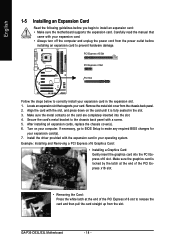
...Installing and Removing a PCI Express x16 Graphics Card: • Installing a Graphics Card: Gently insert the graphics card into the slot. 4. GA-P35-DS3L/S3L Motherboard - 18 - Carefully read the manual that supports your operating system. Locate an expansion slot that came with your expansion card(s). 7. Secure the... card's metal bracket to install an expansion card: • Make sure the motherboard supports the expansion card. Make sure the graphics card is fully seated in the expansion slot. 1. Align the card with the...
...Installing and Removing a PCI Express x16 Graphics Card: • Installing a Graphics Card: Gently insert the graphics card into the slot. 4. GA-P35-DS3L/S3L Motherboard - 18 - Carefully read the manual that supports your operating system. Locate an expansion slot that came with your expansion card(s). 7. Secure the... card's metal bracket to install an expansion card: • Make sure the motherboard supports the expansion card. Make sure the graphics card is fully seated in the expansion slot. 1. Align the card with the...
Manual
Page 19
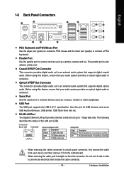
... provides Internet connection at up to an external audio system that supports digital coaxial audio. Hardware Installation Do not rock it straight out from the motherboard. • When removing the cable, pull it side to side to prevent an electrical short inside the cable connector. - 19 - Optical S/PDIF Out Connector This...
... provides Internet connection at up to an external audio system that supports digital coaxial audio. Hardware Installation Do not rock it straight out from the motherboard. • When removing the cable, pull it side to side to prevent an electrical short inside the cable connector. - 19 - Optical S/PDIF Out Connector This...
Manual
Page 20
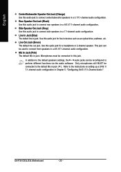
...) Use this audio jack to the instructions on setting up a 2/4/5.1/ 7.1-channel audio configuration in Chapter 5, "Configuring 2/4/5.1/7.1-Channel Audio." Microphones must be connected to this jack. GA-P35-DS3L/S3L Motherboard - 20 - Rear Speaker Out Jack (Black) Use this audio jack to connect rear speakers in a 7.1-channel audio configuration. Side Speaker Out Jack (Gray) Use...
...) Use this audio jack to the instructions on setting up a 2/4/5.1/ 7.1-channel audio configuration in Chapter 5, "Configuring 2/4/5.1/7.1-Channel Audio." Microphones must be connected to this jack. GA-P35-DS3L/S3L Motherboard - 20 - Rear Speaker Out Jack (Black) Use this audio jack to connect rear speakers in a 7.1-channel audio configuration. Side Speaker Out Jack (Gray) Use...
Manual
Page 21
..., make sure your devices are compliant with the connectors you wish to connect. • Before installing the devices, be sure to the connector on the motherboard. - 21 - Unplug the power cord from the power outlet to prevent damage to the devices. • After installing the device and before connecting external devices...
..., make sure your devices are compliant with the connectors you wish to connect. • Before installing the devices, be sure to the connector on the motherboard. - 21 - Unplug the power cord from the power outlet to prevent damage to the devices. • After installing the device and before connecting external devices...

Manual
Page 22
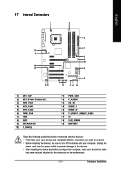
... power supply cable into pins under the protective cover when using a 2x12 power supply, remove the protective cover from the main power connector on the motherboard. The 12V power connector mainly supplies power to the power connector in the correct orientation. When using a 2x10 power supply. 3 4 1 2 ATX_12V ATX_12V ... PS_ON(soft On/Off) GND GND GND -5V +5V +5V +5V (Only for 2x12-pinATX) GND (Only for 2x12-pin ATX) GA-P35-DS3L/S3L Motherboard - 22 - English 1/2) ATX_12V/ATX (2x2 12V Power Connector and 2x12 Main Power Connector) With the use of the power connector, the...
... power supply cable into pins under the protective cover when using a 2x12 power supply, remove the protective cover from the main power connector on the motherboard. The 12V power connector mainly supplies power to the power connector in the correct orientation. When using a 2x10 power supply. 3 4 1 2 ATX_12V ATX_12V ... PS_ON(soft On/Off) GND GND GND -5V +5V +5V +5V (Only for 2x12-pinATX) GND (Only for 2x12-pin ATX) GA-P35-DS3L/S3L Motherboard - 22 - English 1/2) ATX_12V/ATX (2x2 12V Power Connector and 2x12 Main Power Connector) With the use of the power connector, the...
Manual
Page 23
... header supplies a +12V power voltage and possesses a foolproof insertion design. Hardware Installation English 3/4/5/6) CPU_FAN/SYS_FAN1/SYS_FAN2/PWR_FAN (Fan Headers) The motherboard has a 4-pin CPU fan header (CPU_FAN), a 3-pin system fan header (SYS_FAN1), a 4-pin system fan header (SYS_FAN2) and a 3-pin power ...fan header (PWR_FAN). The motherboard supports CPU fan speed control, which requires the use of floppy disk drives supported are designed with fan speed control design. Overheating ...
... header supplies a +12V power voltage and possesses a foolproof insertion design. Hardware Installation English 3/4/5/6) CPU_FAN/SYS_FAN1/SYS_FAN2/PWR_FAN (Fan Headers) The motherboard has a 4-pin CPU fan header (CPU_FAN), a 3-pin system fan header (SYS_FAN1), a 4-pin system fan header (SYS_FAN2) and a 3-pin power ...fan header (PWR_FAN). The motherboard supports CPU fan speed control, which requires the use of floppy disk drives supported are designed with fan speed control design. Overheating ...


