
Manual
Page 1
GA-P31-DS3/ GA-P31-DS3L/ GA-P31-S3L LGA775 socket motherboard for Intel® CoreTM processor family/ Intel® Pentium® processor family/Intel® Celeron® processor family User's Manual Rev. 1001 12ME-P31DS3-1001R * The WEEE marking on the product indicates this product must not be disposed of with user's other household waste and must be handed over to a designated collection point for the recycling of waste electrical and electronic equipment!! * The WEEE marking applies only in European Union's member states.
GA-P31-DS3/ GA-P31-DS3L/ GA-P31-S3L LGA775 socket motherboard for Intel® CoreTM processor family/ Intel® Pentium® processor family/Intel® Celeron® processor family User's Manual Rev. 1001 12ME-P31DS3-1001R * The WEEE marking on the product indicates this product must not be disposed of with user's other household waste and must be handed over to a designated collection point for the recycling of waste electrical and electronic equipment!! * The WEEE marking applies only in European Union's member states.

Manual
Page 2
Motherboard GA-P31-DS3/GA-P31-DS3L/GA-P31-S3L Jul. 20, 2007 Motherboard GA-P31-DS3/GA-P31-DS3L/ GA-P31-S3L Jul. 20, 2007
Motherboard GA-P31-DS3/GA-P31-DS3L/GA-P31-S3L Jul. 20, 2007 Motherboard GA-P31-DS3/GA-P31-DS3L/ GA-P31-S3L Jul. 20, 2007

Manual
Page 3
... prior notice. Disclaimer Information in the use GIGABYTE's unique features, read or download the information on/from the Support\Motherboard\Technology Guide page on your motherboard revision before updating motherboard BIOS, drivers, or when looking for technical information. Check your motherboard looks like this manual is protected by copyright... in this manual may be made by GIGA-BYTE TECHNOLOGY CO., LTD as the exclu- is the property of GIGABYTE branded motherboards. Changes to their respective owners. For product-related information, check on our website at: http://www...
... prior notice. Disclaimer Information in the use GIGABYTE's unique features, read or download the information on/from the Support\Motherboard\Technology Guide page on your motherboard revision before updating motherboard BIOS, drivers, or when looking for technical information. Check your motherboard looks like this manual is protected by copyright... in this manual may be made by GIGA-BYTE TECHNOLOGY CO., LTD as the exclu- is the property of GIGABYTE branded motherboards. Changes to their respective owners. For product-related information, check on our website at: http://www...

Manual
Page 4
Table of Contents Box Contents ...6 OptionalItems ...6 GA-P31-DS3/DS3L/S3L Motherboard Layout 7 Block Diagram ...8 Chapter 1 Hardware Installation 9 1-1 Installation Precautions 9 1-2 Product Specifications 10 1-3 Installing the CPU and CPU Cooler 13 1-3-1 Installing the CPU 13 1-3-2 Installing the CPU ...
Table of Contents Box Contents ...6 OptionalItems ...6 GA-P31-DS3/DS3L/S3L Motherboard Layout 7 Block Diagram ...8 Chapter 1 Hardware Installation 9 1-1 Installation Precautions 9 1-2 Product Specifications 10 1-3 Installing the CPU and CPU Cooler 13 1-3-1 Installing the CPU 13 1-3-2 Installing the CPU ...

Manual
Page 6
.... 12CR1-1SPDIN-01/R) - 6 - The box contents are for reference only and the actual items shall depend on product package you obtain. Box Contents GA-P31-DS3, GA-P31-DS3L or GA-P31-S3L motherboard Motherboard driver disk User's Manual Quick Installation Guide Intel® LGA775 CPU Installation Guide One IDE cable and one floppy disk drive cable Two SATA...
.... 12CR1-1SPDIN-01/R) - 6 - The box contents are for reference only and the actual items shall depend on product package you obtain. Box Contents GA-P31-DS3, GA-P31-DS3L or GA-P31-S3L motherboard Motherboard driver disk User's Manual Quick Installation Guide Intel® LGA775 CPU Installation Guide One IDE cable and one floppy disk drive cable Two SATA...

Manual
Page 7
GA-P31-DS3/DS3L/S3L Motherboard Layout KB_MS COAXIAL OPTICAL ATX_12V LGA775 CPU_FAN COMA LPT PWR_FAN GA-P31-DS3/DS3L/S3L USB USB LAN F_AUDIO Intel® P31 AUDIO SYS_FAN1 DDRII1 PCIE_3 ATX CD_IN RTL8111B PCIE_16 DDRII2 DDRII3 DDRII4 PCIE_1 CLR_CMOS SPDIF_O CODEC PCIE_2 PCI1 SPDIF_I PCI2 IT8718 PCI3 CI FDD Intel® ICH7 BAT SATAII0 SATAII2 SYS_FAN2 BIOS SATAII1 SATAII3 IDE1 PWR_LED F_PANEL F_USB1 F_USB2 "*" Only the GA-P31-DS3/DS3L adopts All-Solid Capacitor design. - 7 -
GA-P31-DS3/DS3L/S3L Motherboard Layout KB_MS COAXIAL OPTICAL ATX_12V LGA775 CPU_FAN COMA LPT PWR_FAN GA-P31-DS3/DS3L/S3L USB USB LAN F_AUDIO Intel® P31 AUDIO SYS_FAN1 DDRII1 PCIE_3 ATX CD_IN RTL8111B PCIE_16 DDRII2 DDRII3 DDRII4 PCIE_1 CLR_CMOS SPDIF_O CODEC PCIE_2 PCI1 SPDIF_I PCI2 IT8718 PCI3 CI FDD Intel® ICH7 BAT SATAII0 SATAII2 SYS_FAN2 BIOS SATAII1 SATAII3 IDE1 PWR_LED F_PANEL F_USB1 F_USB2 "*" Only the GA-P31-DS3/DS3L adopts All-Solid Capacitor design. - 7 -

Manual
Page 9
... turned off. • Before turning on the power, make sure they are connected tightly and securely. • When handling the motherboard, avoid touching any installation steps or have it on top of an antistatic pad or within a electrostatic shielding container. • Before... unplugging the power supply cable from the power outlet before installing or removing the motherboard or other hardware components. • When connecting hardware components to the internal connectors on the computer power during the installation process ...
... turned off. • Before turning on the power, make sure they are connected tightly and securely. • When handling the motherboard, avoid touching any installation steps or have it on top of an antistatic pad or within a electrostatic shielding container. • Before... unplugging the power supply cable from the power outlet before installing or removing the motherboard or other hardware components. • When connecting hardware components to the internal connectors on the computer power during the installation process ...

Manual
Page 10
GA-P31-DS3/DS3L/S3L Motherboard - 10 - English 1-2 Product Specifications CPU Front Side Bus Chipset ...Edition/Intel® Pentium® 4 processor/ Intel® Celeron® processor in the LGA 775 package (Go to GIGABYTE's website for the latest CPU support list.) Š Support for Intel® Hyper-Threading Technology Š L2 cache ... 1) Š Dual channel memory architecture Š Support for DDR2 800/667 MHz memory modules (Note 2) (Go to GIGABYTE's website for the latest memory support list.) Š Realtek ALC888 codec Š High Definition Audio Š 2/4/5.1/7.1-channel &#...
GA-P31-DS3/DS3L/S3L Motherboard - 10 - English 1-2 Product Specifications CPU Front Side Bus Chipset ...Edition/Intel® Pentium® 4 processor/ Intel® Celeron® processor in the LGA 775 package (Go to GIGABYTE's website for the latest CPU support list.) Š Support for Intel® Hyper-Threading Technology Š L2 cache ... 1) Š Dual channel memory architecture Š Support for DDR2 800/667 MHz memory modules (Note 2) (Go to GIGABYTE's website for the latest memory support list.) Š Realtek ALC888 codec Š High Definition Audio Š 2/4/5.1/7.1-channel &#...
Manual
Page 12
For example, 4 GB of memory is reserved for more information.) (Note 3) Available functions in Easytune may differ by motherboard model. English Unique Features Bundled Software Operating System Form Factor Š Support for @BIOS Š Support for Download Center Š Support for Q-Flash Š Support ... from the original frequency. (Please refer to to Page 16 for system usage and therefore the actual memory size is less than the stated amount. GA-P31-DS3/DS3L/S3L Motherboard - 12 -
For example, 4 GB of memory is reserved for more information.) (Note 3) Available functions in Easytune may differ by motherboard model. English Unique Features Bundled Software Operating System Form Factor Š Support for @BIOS Š Support for Download Center Š Support for Q-Flash Š Support ... from the original frequency. (Please refer to to Page 16 for system usage and therefore the actual memory size is less than the stated amount. GA-P31-DS3/DS3L/S3L Motherboard - 12 -

Manual
Page 13
...A BIOS that supports HT Technology and has it does not meet the standard requirements for the peripherals. Locate the alignment keys on the motherboard CPU socket and the notches on the computer if the CPU cooler is not installed, otherwise overheating and damage of the CPU. LGA775 ... Installing the CPU and CPU Cooler Read the following guidelines before you begin to install the CPU: • Make sure that the motherboard supports the CPU. (Go to GIGABYTE's website for the latest CPU support list.) • Always turn on the CPU. Hyper-Threading Technology System Requirements: (Go to ...
...A BIOS that supports HT Technology and has it does not meet the standard requirements for the peripherals. Locate the alignment keys on the motherboard CPU socket and the notches on the computer if the CPU cooler is not installed, otherwise overheating and damage of the CPU. LGA775 ... Installing the CPU and CPU Cooler Read the following guidelines before you begin to install the CPU: • Make sure that the motherboard supports the CPU. (Go to GIGABYTE's website for the latest CPU support list.) • Always turn on the CPU. Hyper-Threading Technology System Requirements: (Go to ...

Manual
Page 14
...install the CPU into its locked position. Step 4: Hold the CPU with the socket alignment keys) and gently insert the CPU into position. GA-P31-DS3/DS3L/S3L Motherboard - 14 - English B. Step 2: Remove the protective socket cover. Follow the steps below to the CPU. Step 5: Once the CPU is... properly inserted, replace the load plate and push the CPU socket lever back into the motherboard CPU socket. Step 3: Lift the metal load plate...
...install the CPU into its locked position. Step 4: Hold the CPU with the socket alignment keys) and gently insert the CPU into position. GA-P31-DS3/DS3L/S3L Motherboard - 14 - English B. Step 2: Remove the protective socket cover. Follow the steps below to the CPU. Step 5: Once the CPU is... properly inserted, replace the load plate and push the CPU socket lever back into the motherboard CPU socket. Step 3: Lift the metal load plate...

Manual
Page 15
...on installing the cooler.) Step 5: After the installation, check the back of the motherboard. Check that the Male and Female push pins are joined closely. (Refer to your CPU cooler installation manual...four push pins through the pin holes on the surface of thermal grease on the motherboard. Push down each push pin. English 1-3-2 Installing the CPU Cooler Follow the steps below to correctly install... the CPU cooler on the motherboard. (The following procedure uses Intel® boxed cooler as the picture above, the installation is...
...on installing the cooler.) Step 5: After the installation, check the back of the motherboard. Check that the Male and Female push pins are joined closely. (Refer to your CPU cooler installation manual...four push pins through the pin holes on the surface of thermal grease on the motherboard. Push down each push pin. English 1-3-2 Installing the CPU Cooler Follow the steps below to correctly install... the CPU cooler on the motherboard. (The following procedure uses Intel® boxed cooler as the picture above, the installation is...

Manual
Page 16
...switch the direction. 1-4-1 Dual Channel Memory Configuration This motherboard provides four DDR2 memory sockets and supports Dual Channel Technology. quency being reduced from the power outlet before installing the memory to GIGABYTE's website for optimum performance. 3. Dual Channel mode cannot...(SS=Single-Sided, DS=Double-Sided, "- -"=No Memory) Memory configurations below , system instability or unexpected results may occur. SS SS - - GA-P31-DS3/DS3L/S3L Motherboard - 16 - After the memory is installed. 2. DS/SS DS/SS - - - - DS/SS DS/SS - - DS/SS SS ...
...switch the direction. 1-4-1 Dual Channel Memory Configuration This motherboard provides four DDR2 memory sockets and supports Dual Channel Technology. quency being reduced from the power outlet before installing the memory to GIGABYTE's website for optimum performance. 3. Dual Channel mode cannot...(SS=Single-Sided, DS=Double-Sided, "- -"=No Memory) Memory configurations below , system instability or unexpected results may occur. SS SS - - GA-P31-DS3/DS3L/S3L Motherboard - 16 - After the memory is installed. 2. DS/SS DS/SS - - - - DS/SS DS/SS - - DS/SS SS ...

Manual
Page 17
... , make sure to turn off the computer and unplug the power cord from the power outlet to prevent damage to install DDR2 DIMMs on this motherboard. Step 1: Note the orientation of the memory socket. Spread the retaining clips at both ends of the memory module. Step 2: The clips at both ends...
... , make sure to turn off the computer and unplug the power cord from the power outlet to prevent damage to install DDR2 DIMMs on this motherboard. Step 1: Note the orientation of the memory socket. Spread the retaining clips at both ends of the memory module. Step 2: The clips at both ends...

Manual
Page 18
.... 1. Remove the metal slot cover from the power outlet before you begin to install an expansion card: • Make sure the motherboard supports the expansion card. Install the driver provided with the slot, and press down on the card until it is locked by the ... inserted into the PCI Express x16 slot. If necessary, go to BIOS Setup to make any required BIOS changes for your computer. GA-P31-DS3/DS3L/S3L Motherboard - 18 - English 1-5 Installing an Expansion Card Read the following guidelines before installing an expansion card to prevent hardware damage. Locate ...
.... 1. Remove the metal slot cover from the power outlet before you begin to install an expansion card: • Make sure the motherboard supports the expansion card. Install the driver provided with the slot, and press down on the card until it is locked by the ... inserted into the PCI Express x16 slot. If necessary, go to BIOS Setup to make any required BIOS changes for your computer. GA-P31-DS3/DS3L/S3L Motherboard - 18 - English 1-5 Installing an Expansion Card Read the following guidelines before installing an expansion card to prevent hardware damage. Locate ...

Manual
Page 19
... occurring • When removing the cable connected to connect a PS/2 keyboard. Before using this feature, ensure that your device and then remove it from the motherboard. • When removing the cable, pull it side to side to an external audio system that supports digital coaxial audio. Serial Port Use the serial...
... occurring • When removing the cable connected to connect a PS/2 keyboard. Before using this feature, ensure that your device and then remove it from the motherboard. • When removing the cable, pull it side to side to an external audio system that supports digital coaxial audio. Serial Port Use the serial...

Manual
Page 20
... perform different functions via the audio software. Microphones must be used to this audio jack for line in a 5.1/7.1-channel audio configuration. Use this jack. GA-P31-DS3/DS3L/S3L Motherboard - 20 - Only microphones still MUST be reconfigured to the default Mic in a 4/5.1/7.1-channel audio configuration. Side Speaker Out Jack (Gray) Use this audio jack...
... perform different functions via the audio software. Microphones must be used to this audio jack for line in a 5.1/7.1-channel audio configuration. Use this jack. GA-P31-DS3/DS3L/S3L Motherboard - 20 - Only microphones still MUST be reconfigured to the default Mic in a 4/5.1/7.1-channel audio configuration. Side Speaker Out Jack (Gray) Use this audio jack...

Manual
Page 21
... 12) F_PANEL 13) CD_IN 14) SPDIF_I 15) SPDIF_O 16) F_USB1/F_USB2 17) CI 18) CLR_CMOS 19) BAT Read the following guidelines before turning on the motherboard. - 21 -
... 12) F_PANEL 13) CD_IN 14) SPDIF_I 15) SPDIF_O 16) F_USB1/F_USB2 17) CI 18) CLR_CMOS 19) BAT Read the following guidelines before turning on the motherboard. - 21 -

Manual
Page 22
...GND PS_ON(soft On/Off) GND GND GND -5V +5V +5V +5V (Only for 2x12-pinATX) GND (Only for 2x12-pin ATX) GA-P31-DS3/DS3L/S3L Motherboard - 22 - The 12V power connector mainly supplies power to the power connector in the correct orientation. Before connecting the power connector, first make... sure the power supply is turned off and all the components on the motherboard. Do not insert the power supply cable into...
...GND PS_ON(soft On/Off) GND GND GND -5V +5V +5V +5V (Only for 2x12-pinATX) GND (Only for 2x12-pin ATX) GA-P31-DS3/DS3L/S3L Motherboard - 22 - The 12V power connector mainly supplies power to the power connector in the correct orientation. Before connecting the power connector, first make... sure the power supply is turned off and all the components on the motherboard. Do not insert the power supply cable into...
Manual
Page 23
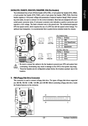
...the connector. 33 1 34 2 - 23 - Hardware Installation Most fans are : 360 KB, 720 KB, 1.2 MB, 1.44 MB, and 2.88 MB. The motherboard supports CPU fan speed control, which requires the use of floppy disk drives supported are designed with fan speed control design. The types of a CPU.... For optimum heat dissipation, it in damage to connect it is the ground wire. English 3/4/5/6) CPU_FAN/SYS_FAN1/SYS_FAN2/PWR_FAN (Fan Headers) The motherboard has a 4-pin CPU fan header (CPU_FAN), a 4-pin system fan header (SYS_FAN2), a 3-pin system fan header (SYS_FAN1), and a 3-pin power ...
...the connector. 33 1 34 2 - 23 - Hardware Installation Most fans are : 360 KB, 720 KB, 1.2 MB, 1.44 MB, and 2.88 MB. The motherboard supports CPU fan speed control, which requires the use of floppy disk drives supported are designed with fan speed control design. The types of a CPU.... For optimum heat dissipation, it in damage to connect it is the ground wire. English 3/4/5/6) CPU_FAN/SYS_FAN1/SYS_FAN2/PWR_FAN (Fan Headers) The motherboard has a 4-pin CPU fan header (CPU_FAN), a 4-pin system fan header (SYS_FAN2), a 3-pin system fan header (SYS_FAN1), and a 3-pin power ...


