Manual
Page 5
... the Q-Flash Utility 62 4-2-2 Updating the BIOS with the @BIOS Utility 65 4-3 EasyTune 5 ...67 4-4 Windows Vista ReadyBoost 68 Chapter 5 Appendix ...69 5-1 Configuring Audio Input and Output 69 5-1-1 Configuring 2/4/5.1/7.1-Channel Audio 69 5-1-2 Installing the S/PDIF In Cable (Optional 71 5-1-3 Configuring Microphone Recording 73 5-1-4 Using the Sound Recorder 75 5-2 Troubleshooting 76 5-2-1 Frequently Asked Questions...
... the Q-Flash Utility 62 4-2-2 Updating the BIOS with the @BIOS Utility 65 4-3 EasyTune 5 ...67 4-4 Windows Vista ReadyBoost 68 Chapter 5 Appendix ...69 5-1 Configuring Audio Input and Output 69 5-1-1 Configuring 2/4/5.1/7.1-Channel Audio 69 5-1-2 Installing the S/PDIF In Cable (Optional 71 5-1-3 Configuring Microphone Recording 73 5-1-4 Using the Sound Recorder 75 5-2 Troubleshooting 76 5-2-1 Frequently Asked Questions...

Manual
Page 7
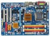
GA-P31-DS3/DS3L/S3L Motherboard Layout KB_MS COAXIAL OPTICAL ATX_12V LGA775 CPU_FAN COMA LPT PWR_FAN GA-P31-DS3/DS3L/S3L USB USB LAN F_AUDIO Intel® P31 AUDIO SYS_FAN1 DDRII1 PCIE_3 ATX CD_IN RTL8111B PCIE_16 DDRII2 DDRII3 DDRII4 PCIE_1 CLR_CMOS SPDIF_O CODEC PCIE_2 PCI1 SPDIF_I PCI2 IT8718 PCI3 CI FDD Intel® ICH7 BAT SATAII0 SATAII2 SYS_FAN2 BIOS SATAII1 SATAII3 IDE1 PWR_LED F_PANEL F_USB1 F_USB2 "*" Only the GA-P31-DS3/DS3L adopts All-Solid Capacitor design. - 7 -
GA-P31-DS3/DS3L/S3L Motherboard Layout KB_MS COAXIAL OPTICAL ATX_12V LGA775 CPU_FAN COMA LPT PWR_FAN GA-P31-DS3/DS3L/S3L USB USB LAN F_AUDIO Intel® P31 AUDIO SYS_FAN1 DDRII1 PCIE_3 ATX CD_IN RTL8111B PCIE_16 DDRII2 DDRII3 DDRII4 PCIE_1 CLR_CMOS SPDIF_O CODEC PCIE_2 PCI1 SPDIF_I PCI2 IT8718 PCI3 CI FDD Intel® ICH7 BAT SATAII0 SATAII2 SYS_FAN2 BIOS SATAII1 SATAII3 IDE1 PWR_LED F_PANEL F_USB1 F_USB2 "*" Only the GA-P31-DS3/DS3L adopts All-Solid Capacitor design. - 7 -

Manual
Page 10
GA-P31-DS3/DS3L/S3L Motherboard - 10 - English 1-2 Product Specifications CPU Front Side Bus Chipset Memory Audio LAN Expansion Slots Storage Interface USB Š Support for an Intel® CoreTM 2 Extreme processor/ Intel® CoreTM 2 Quad processor/Intel® CoreTM 2...Intel® Pentium® 4 processor Extreme Edition/Intel® Pentium® 4 processor/ Intel® Celeron® processor in the LGA 775 package (Go to GIGABYTE's website for the latest CPU support list.) Š Support for Intel® Hyper-Threading Technology Š L2 cache varies with CPU Š 1333/1066/800...
GA-P31-DS3/DS3L/S3L Motherboard - 10 - English 1-2 Product Specifications CPU Front Side Bus Chipset Memory Audio LAN Expansion Slots Storage Interface USB Š Support for an Intel® CoreTM 2 Extreme processor/ Intel® CoreTM 2 Quad processor/Intel® CoreTM 2...Intel® Pentium® 4 processor Extreme Edition/Intel® Pentium® 4 processor/ Intel® Celeron® processor in the LGA 775 package (Go to GIGABYTE's website for the latest CPU support list.) Š Support for Intel® Hyper-Threading Technology Š L2 cache varies with CPU Š 1333/1066/800...

Manual
Page 11
... connectors Š 1 x CPU fan header Š 2 x system fan headers Š 1 x power fan header Š 1 x front panel header Š 1 x front panel audio header Š 1 x CD In connector Š 1 x S/PDIF In header Š 1 x S/PDIF Out header Š 2 x USB 2.0/1.1 headers Š 1 x chassis intrusion... 1 x parallel port Š 1 x serial port Š 4 x USB 2.0/1.1 ports Š 1 x RJ-45 port Š 6 x audio jacks (Center/Subwoofer Speaker Out/Rear Speaker Out/Side Speaker Out/Line In/Line Out/Microphone) I/O Controller Š iTE IT8718 chip Hardware Monitor Š System...
... connectors Š 1 x CPU fan header Š 2 x system fan headers Š 1 x power fan header Š 1 x front panel header Š 1 x front panel audio header Š 1 x CD In connector Š 1 x S/PDIF In header Š 1 x S/PDIF Out header Š 2 x USB 2.0/1.1 headers Š 1 x chassis intrusion... 1 x parallel port Š 1 x serial port Š 4 x USB 2.0/1.1 ports Š 1 x RJ-45 port Š 6 x audio jacks (Center/Subwoofer Speaker Out/Rear Speaker Out/Side Speaker Out/Line In/Line Out/Microphone) I/O Controller Š iTE IT8718 chip Hardware Monitor Š System...

Manual
Page 19
...to side to prevent an electrical short inside the cable connector. - 19 - Serial Port Use the serial port to an external audio system that supports digital optical audio. English 1-6 Back Panel Connectors PS/2 Keyboard and PS/2 Mouse Port Use the upper port (green) to connect a PS/2 ...at up to connect a PS/2 keyboard. Do not rock it straight out from the connector. Optical S/PDIF Out Connector This connector provides digital audio out to connect devices such as a mouse, modem or other peripherals. Connection/ Speed LED Activity LED LAN Port Connection/Speed LED: State ...
...to side to prevent an electrical short inside the cable connector. - 19 - Serial Port Use the serial port to an external audio system that supports digital optical audio. English 1-6 Back Panel Connectors PS/2 Keyboard and PS/2 Mouse Port Use the upper port (green) to connect a PS/2 ...at up to connect a PS/2 keyboard. Do not rock it straight out from the connector. Optical S/PDIF Out Connector This connector provides digital audio out to connect devices such as a mouse, modem or other peripherals. Connection/ Speed LED Activity LED LAN Port Connection/Speed LED: State ...

Manual
Page 20
... in jack. Mic In Jack (Pink) The default Mic in a 4/5.1/7.1-channel audio configuration. Use this audio jack for a headphone or 2-channel speaker. GA-P31-DS3/DS3L/S3L Motherboard - 20 - Side Speaker Out Jack (Gray) Use this audio jack to connect side speakers in a 4/5.1/7.1-channel audio configuration. Line Out Jack (Green) The default line out jack. This jack...
... in jack. Mic In Jack (Pink) The default Mic in a 4/5.1/7.1-channel audio configuration. Use this audio jack for a headphone or 2-channel speaker. GA-P31-DS3/DS3L/S3L Motherboard - 20 - Side Speaker Out Jack (Gray) Use this audio jack to connect side speakers in a 4/5.1/7.1-channel audio configuration. Line Out Jack (Green) The default line out jack. This jack...

Manual
Page 25
... 1 3 MPD- System Status LED S0 On S1 Blinking S3/S4/S5 Off 11) F_AUDIO (Front Panel Audio Header) The front panel audio header supports Intel High Definition audio (HD) and AC'97 audio. Make sure the wire assignments of the module connector match the pin assignments of a single plug. Definition 1...the device unable to the instructions on each wire instead of the motherboard header. For information about connecting the front panel audio module that has separated connectors on how to indicate system power status. The LED keeps blinking when the system is in ...
... 1 3 MPD- System Status LED S0 On S1 Blinking S3/S4/S5 Off 11) F_AUDIO (Front Panel Audio Header) The front panel audio header supports Intel High Definition audio (HD) and AC'97 audio. Make sure the wire assignments of the module connector match the pin assignments of a single plug. Definition 1...the device unable to the instructions on each wire instead of the motherboard header. For information about connecting the front panel audio module that has separated connectors on how to indicate system power status. The LED keeps blinking when the system is in ...

Manual
Page 27
For purchasing the optional S/PDIF in and can connect to an audio device that came with your optical drive to the header. Hardware Installation English 13) CD_IN (CD In Connector) You may connect the audio cable that supports digital audio out via an optional S/PDIF in cable. Pin No. Definition 1 1 CD-L 2 GND 3 GND 4 CD-R 14) SPDIF_I (S/PDIF In Header) This header supports digital S/PDIF in cable, please contact the local dealer. Definition 1 1 Power 2 SPDIFI 3 GND - 27 - Pin No.
For purchasing the optional S/PDIF in and can connect to an audio device that came with your optical drive to the header. Hardware Installation English 13) CD_IN (CD In Connector) You may connect the audio cable that supports digital audio out via an optional S/PDIF in cable. Pin No. Definition 1 1 CD-L 2 GND 3 GND 4 CD-R 14) SPDIF_I (S/PDIF In Header) This header supports digital S/PDIF in cable, please contact the local dealer. Definition 1 1 Power 2 SPDIFI 3 GND - 27 - Pin No.

Manual
Page 28
... out and connects a S/PDIF digital audio cable (provided by expansion cards) for your expansion card. For information about connecting the S/PDIF digital audio cable, carefully read the manual for digital audio output from your motherboard to the USB...audio cable for digital audio output from your motherboard to USB 2.0/1.1 specification. For example, some graphics cards may require you wish to connect an HDMI display to the graphics card and have digital audio output from the power outlet to prevent damage to certain expansion cards like graphics cards and sound cards. GA-P31-DS3/DS3L...
... out and connects a S/PDIF digital audio cable (provided by expansion cards) for your expansion card. For information about connecting the S/PDIF digital audio cable, carefully read the manual for digital audio output from your motherboard to the USB...audio cable for digital audio output from your motherboard to USB 2.0/1.1 specification. For example, some graphics cards may require you wish to connect an HDMI display to the graphics card and have digital audio output from the power outlet to prevent damage to certain expansion cards like graphics cards and sound cards. GA-P31-DS3/DS3L...

Manual
Page 34
...current BIOS settings to the system and BIOS Setup. First enter the profile name (to erase the default profile name, use this task.) GA-P31-DS3/DS3L/S3L Motherboard - 34 - It allows you can also carry out this function to see information about autodetected system/CPU temperature, system voltage...CPU, and the primary display adapter. „ Integrated Peripherals Use this menu to configure all peripheral devices, such as IDE, SATA, USB, integrated audio, and integrated LAN, etc. „ Power Management Setup Use this menu to configure all the changes made in BIOS Setup. „ Set User...
...current BIOS settings to the system and BIOS Setup. First enter the profile name (to erase the default profile name, use this task.) GA-P31-DS3/DS3L/S3L Motherboard - 34 - It allows you can also carry out this function to see information about autodetected system/CPU temperature, system voltage...CPU, and the primary display adapter. „ Integrated Peripherals Use this menu to configure all peripheral devices, such as IDE, SATA, USB, integrated audio, and integrated LAN, etc. „ Power Management Setup Use this menu to configure all the changes made in BIOS Setup. „ Set User...

Manual
Page 40
... to detect USB storage devices, including USB flash drives and USB hard drives during the POST. (Default: Enabled) Azalia Codec Enables or disables the onboard audio function. (Default: Auto) If you wish to settings. English SATA Port 1/3 Set to This value is attached to the motherboard, the Status fields of...USB keyboard to be used in MS-DOS. (Default: Disabled) USB Mouse Support Allows USB mouse to be automatically set to Ch. 1 Master/Slave. GA-P31-DS3/DS3L/S3L Motherboard - 40 - If no LAN cable is dependent on the On-Chip SATA Mode and PATA IDE Set to install a 3rd party add-...
... to detect USB storage devices, including USB flash drives and USB hard drives during the POST. (Default: Enabled) Azalia Codec Enables or disables the onboard audio function. (Default: Auto) If you wish to settings. English SATA Port 1/3 Set to This value is attached to the motherboard, the Status fields of...USB keyboard to be used in MS-DOS. (Default: Disabled) USB Mouse Support Allows USB mouse to be automatically set to Ch. 1 Master/Slave. GA-P31-DS3/DS3L/S3L Motherboard - 40 - If no LAN cable is dependent on the On-Chip SATA Mode and PATA IDE Set to install a 3rd party add-...

Manual
Page 69
... In Front Speaker Out the user to change the function for microphone functionality. • If your front panel audio supports Intel HD Audio standard, you can retask the Center/Subwoofer speaker out jack to the Mic in or Line in jack and ...1KHz/ 48KHz/ 96KHz/192KHz sampling rate. Appendix English Chapter 5 Appendix 5-1 Configuring Audio Input and Output 5-1-1 Configuring 2/4/5.1/7.1-Channel Audio The motherboard provides six audio jacks on the back panel which support 2/4/5.1/7.1-channel audio. The picture to the following instructions use Windows XP as the example operating system...
... In Front Speaker Out the user to change the function for microphone functionality. • If your front panel audio supports Intel HD Audio standard, you can retask the Center/Subwoofer speaker out jack to the Mic in or Line in jack and ...1KHz/ 48KHz/ 96KHz/192KHz sampling rate. Appendix English Chapter 5 Appendix 5-1 Configuring Audio Input and Output 5-1-1 Configuring 2/4/5.1/7.1-Channel Audio The motherboard provides six audio jacks on the back panel which support 2/4/5.1/7.1-channel audio. The picture to the following instructions use Windows XP as the example operating system...

Manual
Page 70
... On the Global Connector Settings box, select the Disable front panel jack detection check box. Configuring AC'97 Audio: If you want to an audio jack, the Connected device box appears. GA-P31-DS3/DS3L/S3L Motherboard - 70 - In the speaker list on the left, select 2CH Speaker, 4CH Speaker, 6CH Speaker, or 8CH Speaker...
... On the Global Connector Settings box, select the Disable front panel jack detection check box. Configuring AC'97 Audio: If you want to an audio jack, the Connected device box appears. GA-P31-DS3/DS3L/S3L Motherboard - 70 - In the speaker list on the left, select 2CH Speaker, 4CH Speaker, 6CH Speaker, or 8CH Speaker...

Manual
Page 71
Appendix Optical S/PDIF In Coaxial S/PDIF In S/PDIF In: The S/PDIF in functionality. Step 2: Secure the metal bracket to the computer for audio processing. Installing the S/PDIF In Cable: Step 1: First, attach the connector at the end of the cable to the SPDIF_IN header on your motherboard. English 5-1-2 Installing the S/PDIF In Cable (Optional) The S/PDIF in cable provides S/PDIF in jacks allow you to input digital audio signals to the chassis back panel with a screw. - 71 - A.
Appendix Optical S/PDIF In Coaxial S/PDIF In S/PDIF In: The S/PDIF in functionality. Step 2: Secure the metal bracket to the computer for audio processing. Installing the S/PDIF In Cable: Step 1: First, attach the connector at the end of the cable to the SPDIF_IN header on your motherboard. English 5-1-2 Installing the S/PDIF In Cable (Optional) The S/PDIF in cable provides S/PDIF in jacks allow you to input digital audio signals to the chassis back panel with a screw. - 71 - A.

Manual
Page 72
S/PDIF Coaxial Cable S/PDIF Optical Cable C. GA-P31-DS3/DS3L/S3L Motherboard - 72 - In the S/PDIF In/Out Settings dialog box, select an output sampling rate and select (or disable) the output source. B. English S/PDIF Out: The S/PDIF out jacks can transmit audio signals to an external decoder for decoding to an external decoder for...
S/PDIF Coaxial Cable S/PDIF Optical Cable C. GA-P31-DS3/DS3L/S3L Motherboard - 72 - In the S/PDIF In/Out Settings dialog box, select an output sampling rate and select (or disable) the output source. B. English S/PDIF Out: The S/PDIF out jacks can transmit audio signals to an external decoder for decoding to an external decoder for...

Manual
Page 73
... jack (pink) on the back panel or the Line in your system tray and click it to access the Audio Control Panel. Appendix English 5-1-3 Configuring Microphone Recording Step 1: After installing the audio driver, the Audio Manager icon will appear in jack on the front panel. Step 3: Locate the Volume icon in your system...
... jack (pink) on the back panel or the Line in your system tray and click it to access the Audio Control Panel. Appendix English 5-1-3 Configuring Microphone Recording Step 1: After installing the audio driver, the Audio Manager icon will appear in jack on the front panel. Step 3: Locate the Volume icon in your system...

Manual
Page 74
English Step 4: To hear the sound being recorded during the record- In the Mixer device list, select Realtek HD Audio Input. To hear the sound being recorded during the recording process when using the microphone function on the back panel, do not select the... show and click OK to the Options menu and then choose Properties. Step 5: Next, while in the Mixer devie list GA-P31-DS3/DS3L/S3L Motherboard Recording Control - 74 - Select Realtek HD Audio Input in Master Volume, go to complete. Then set the volume at a middle level. It is recommended that you need...
English Step 4: To hear the sound being recorded during the record- In the Mixer device list, select Realtek HD Audio Input. To hear the sound being recorded during the recording process when using the microphone function on the back panel, do not select the... show and click OK to the Options menu and then choose Properties. Step 5: Next, while in the Mixer devie list GA-P31-DS3/DS3L/S3L Motherboard Recording Control - 74 - Select Realtek HD Audio Input in Master Volume, go to complete. Then set the volume at a middle level. It is recommended that you need...

Manual
Page 75
... recording and playing sound for the microphone, go to the computer. 2. In the Open dialog box, select the sound (.wav) file you have connected the audio input device (e.g. In the Other Controls field, select the 1 Microphone Boost check box. microphone) to Options in Master Volume and select Advanced Controls. On the...
... recording and playing sound for the microphone, go to the computer. 2. In the Open dialog box, select the sound (.wav) file you have connected the audio input device (e.g. In the Other Controls field, select the 1 Microphone Boost check box. microphone) to Options in Master Volume and select Advanced Controls. On the...


