Manual
Page 1
GA-N650SLI-DS4L LGA775 socket motherboard for Intel® CoreTM processor family/ Intel® Pentium® processor family/Intel® Celeron® processor family User's Manual Rev. 1001 12ME-N650DS4L-1001R
GA-N650SLI-DS4L LGA775 socket motherboard for Intel® CoreTM processor family/ Intel® Pentium® processor family/Intel® Celeron® processor family User's Manual Rev. 1001 12ME-N650DS4L-1001R
Manual
Page 4
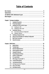
Table of Contents Box Contents ...6 OptionalItems ...6 GA-N650SLI-DS4L Motherboard Layout 7 Block Diagram ...8 Chapter 1 Hardware Installation 9 1-1 Installation Precautions 9 1-2 Product Specifications 10 1-3 Installing the CPU and CPU Cooler 13 1-3-1 Installing the CPU 13 1-3-2 Installing the ...
Table of Contents Box Contents ...6 OptionalItems ...6 GA-N650SLI-DS4L Motherboard Layout 7 Block Diagram ...8 Chapter 1 Hardware Installation 9 1-1 Installation Precautions 9 1-2 Product Specifications 10 1-3 Installing the CPU and CPU Cooler 13 1-3-1 Installing the CPU 13 1-3-2 Installing the ...
Manual
Page 6
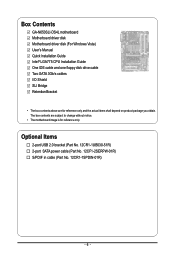
The box contents are for reference only. Box Contents GA-N650SLI-DS4L motherboard Motherboard driver disk Motherboard driver disk (For Windows Vista) User's Manual Quick Installation Guide Intel® LGA775 CPU Installation Guide One IDE cable and ...
The box contents are for reference only. Box Contents GA-N650SLI-DS4L motherboard Motherboard driver disk Motherboard driver disk (For Windows Vista) User's Manual Quick Installation Guide Intel® LGA775 CPU Installation Guide One IDE cable and ...
Manual
Page 10
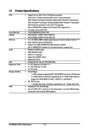
...devices - 4 x SATA 3Gb/s connectors supporting up to 1 floppy disk drive Š Integrated in the LGA 775 package (Go to GIGABYTE's website for the latest CPU support list.) Š L2 cache varies with CPU Š 1333/1066/800/533 MHz FSB Š...GIGABYTE's website for the latest memory support list.) Š Realtek ALC888 codec Š High Definition Audio Š 2/4/5.1/7.1-channel Š Support for S/PDIF In/Out Š Support for SATA RAID 0, RAID 1, RAID 0+1, and RAID 5 Š iTE IT8718 chip: - 1 x floppy disk drive connector supporting up to the internal USB headers) GA-N650SLI-DS4L...
...devices - 4 x SATA 3Gb/s connectors supporting up to 1 floppy disk drive Š Integrated in the LGA 775 package (Go to GIGABYTE's website for the latest CPU support list.) Š L2 cache varies with CPU Š 1333/1066/800/533 MHz FSB Š...GIGABYTE's website for the latest memory support list.) Š Realtek ALC888 codec Š High Definition Audio Š 2/4/5.1/7.1-channel Š Support for S/PDIF In/Out Š Support for SATA RAID 0, RAID 1, RAID 0+1, and RAID 5 Š iTE IT8718 chip: - 1 x floppy disk drive connector supporting up to the internal USB headers) GA-N650SLI-DS4L...
Manual
Page 12
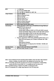
... - Increase CPU voltage (Note 4) - Increase VCC12_DL voltage by 0.1V or 0.2V Š Frequency adjustments in Easytune may differ by 0.025V to 0.35V with 0.05V increment - GA-N650SLI-DS4L Motherboard - 12 - Increase DDR2 voltage by motherboard model. (Note 4) The adjustable CPU voltage range depends on the CPU being used.
... - Increase CPU voltage (Note 4) - Increase VCC12_DL voltage by 0.1V or 0.2V Š Frequency adjustments in Easytune may differ by 0.025V to 0.35V with 0.05V increment - GA-N650SLI-DS4L Motherboard - 12 - Increase DDR2 voltage by motherboard model. (Note 4) The adjustable CPU voltage range depends on the CPU being used.
Manual
Page 14
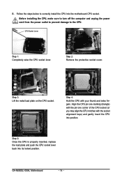
... the load plate and push the CPU socket lever back into the motherboard CPU socket. B. Step 3: Lift the metal load plate on the CPU socket. GA-N650SLI-DS4L Motherboard - 14 - Follow the steps below to the CPU. Before installing the CPU, make sure to turn off the computer and unplug the power cord...
... the load plate and push the CPU socket lever back into the motherboard CPU socket. B. Step 3: Lift the metal load plate on the CPU socket. GA-N650SLI-DS4L Motherboard - 14 - Follow the steps below to the CPU. Before installing the CPU, make sure to turn off the computer and unplug the power cord...
Manual
Page 16
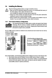
...Double-Sided, "- -"=No Memory) DDRII1 DDRII2 DDRII3 DDRII4 Due to prevent hardware damage. • Memory modules have a foolproof design. GA-N650SLI-DS4L Motherboard - 16 - If you begin to insert the memory, switch the direction. 1-4-1 Dual Channel Memory Configuration This motherboard provides four DDR2...DDRII4 Dual Channel Memory Configurations Table DDRII1 DDRII2 DDRII3 Two Modules DS/SS - - A memory module can be used . (Go to GIGABYTE's website for the latest memory support list.) • Always turn off the computer and unplug the power cord from the power outlet ...
...Double-Sided, "- -"=No Memory) DDRII1 DDRII2 DDRII3 DDRII4 Due to prevent hardware damage. • Memory modules have a foolproof design. GA-N650SLI-DS4L Motherboard - 16 - If you begin to insert the memory, switch the direction. 1-4-1 Dual Channel Memory Configuration This motherboard provides four DDR2...DDRII4 Dual Channel Memory Configurations Table DDRII1 DDRII2 DDRII3 Two Modules DS/SS - - A memory module can be used . (Go to GIGABYTE's website for the latest memory support list.) • Always turn off the computer and unplug the power cord from the power outlet ...
Manual
Page 18
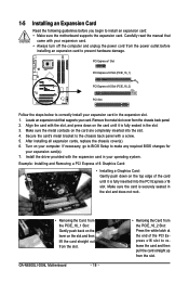
... slot to release the card and then pull the card straight up from the chassis back panel. 2. Install the driver provided with your expansion card(s). 7. GA-N650SLI-DS4L Motherboard - 18 - • Removing the Card from the PCIE_16_2 Slot: Press the white latch at the end of the card until it is fully seated...
... slot to release the card and then pull the card straight up from the chassis back panel. 2. Install the driver provided with your expansion card(s). 7. GA-N650SLI-DS4L Motherboard - 18 - • Removing the Card from the PCIE_16_2 Slot: Press the white latch at the end of the card until it is fully seated...
Manual
Page 20
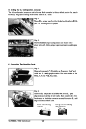
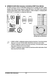
... GC-DGBR2-RH) in "1-5 Installing an Expansion Card" and install two SLI-ready graphics cards of the same model on top of the graphics card GA-N650SLI-DS4L Motherboard - 20 - Step 1: Move all the jumper caps from Normal Mode to pins 1-2, including the JP1 jumper. Step 2: The finished SLI jumper configurations are set...
... GC-DGBR2-RH) in "1-5 Installing an Expansion Card" and install two SLI-ready graphics cards of the same model on top of the graphics card GA-N650SLI-DS4L Motherboard - 20 - Step 1: Move all the jumper caps from Normal Mode to pins 1-2, including the JP1 jumper. Step 2: The finished SLI jumper configurations are set...
Manual
Page 22
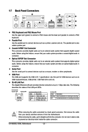
... provides Internet connection at up to connect devices such as a mouse, modem or other peripherals. Parallel Port Use the parallel port to connect a PS/2 keyboard. GA-N650SLI-DS4L Motherboard - 22 - 1-7 Back Panel Connectors PS/2 Keyboard and PS/2 Mouse Port Use the upper port (green) to connect a PS/2 mouse and the lower port (purple...
... provides Internet connection at up to connect devices such as a mouse, modem or other peripherals. Parallel Port Use the parallel port to connect a PS/2 keyboard. GA-N650SLI-DS4L Motherboard - 22 - 1-7 Back Panel Connectors PS/2 Keyboard and PS/2 Mouse Port Use the upper port (green) to connect a PS/2 mouse and the lower port (purple...
Manual
Page 24
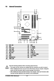
... device and before connecting external devices: • First make sure the device cable has been securely attached to turn off the devices and your computer. GA-N650SLI-DS4L Motherboard - 24 -
... device and before connecting external devices: • First make sure the device cable has been securely attached to turn off the devices and your computer. GA-N650SLI-DS4L Motherboard - 24 -
Manual
Page 26
... power connector wire indicates a positive connection and requires a +12V voltage. When connecting a fan cable, be sure to connect it in the correct orientation. Pin No. GA-N650SLI-DS4L Motherboard - 26 - Most fans are designed with color-coded power connector wires. A red power connector wire indicates a positive connection and requires a +12V voltage. Do not...
... power connector wire indicates a positive connection and requires a +12V voltage. When connecting a fan cable, be sure to connect it in the correct orientation. Pin No. GA-N650SLI-DS4L Motherboard - 26 - Most fans are designed with color-coded power connector wires. A red power connector wire indicates a positive connection and requires a +12V voltage. Do not...
Manual
Page 28
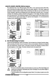
... 7 1 7 1 SATAII0 7 1 SATAII2 Pin No. 1 2 3 4 5 6 7 Definition GND TXP TXN GND RXN RXP GND Please connect the L-shaped end of hard drives must be an even number. GA-N650SLI-DS4L Motherboard - 28 - The nVIDIA® nForce 650i SLI controller supports RAID 0, RAID 1, RAID 5 and RAID 0+1. If more than two hard drives are compatible with SATA...
... 7 1 7 1 SATAII0 7 1 SATAII2 Pin No. 1 2 3 4 5 6 7 Definition GND TXP TXN GND RXN RXP GND Please connect the L-shaped end of hard drives must be an even number. GA-N650SLI-DS4L Motherboard - 28 - The nVIDIA® nForce 650i SLI controller supports RAID 0, RAID 1, RAID 5 and RAID 0+1. If more than two hard drives are compatible with SATA...
Manual
Page 30
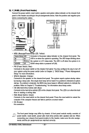
... front panel design may configure the way to turn off (S5). • PW (Power Switch, Red): Connects to this header according to indicate the problem. GA-N650SLI-DS4L Motherboard - 30 -
... front panel design may configure the way to turn off (S5). • PW (Power Switch, Red): Connects to this header according to indicate the problem. GA-N650SLI-DS4L Motherboard - 30 -
Manual
Page 32
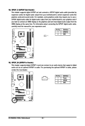
... display to the graphics card and have digital audio output from your expansion card. For purchasing the optional S/PDIF in cable. Definition 1 1 Power 2 SPDIFI 3 GND GA-N650SLI-DS4L Motherboard - 32 - 15) SPDIF_O (S/PDIF Out Header) This header supports digital S/PDIF out and connects a S/PDIF digital audio cable (provided by expansion cards) for digital...
... display to the graphics card and have digital audio output from your expansion card. For purchasing the optional S/PDIF in cable. Definition 1 1 Power 2 SPDIFI 3 GND GA-N650SLI-DS4L Motherboard - 32 - 15) SPDIF_O (S/PDIF Out Header) This header supports digital S/PDIF out and connects a S/PDIF digital audio cable (provided by expansion cards) for digital...
Manual
Page 34
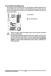
... before turning on the two pins to temporarily short the two pins or use a metal object like a screwdriver to Chapter 2, "BIOS Setup," for a few seconds. GA-N650SLI-DS4L Motherboard - 34 - Failure to do so may cause damage to the motherboard. • After system restart, go to BIOS Setup to load factory defaults (select...
... before turning on the two pins to temporarily short the two pins or use a metal object like a screwdriver to Chapter 2, "BIOS Setup," for a few seconds. GA-N650SLI-DS4L Motherboard - 34 - Failure to do so may cause damage to the motherboard. • After system restart, go to BIOS Setup to load factory defaults (select...
Manual
Page 36
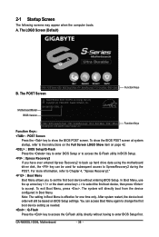
...access the Q-Flash utility in Boot Menu is effective for subsequent access to access the Q-Flash utility directly without entering BIOS Setup. GA-N650SLI-DS4L Motherboard - 36 - The POST Screen Function Keys Motherboard Model BIOS Version Award Modular BIOS v6.00PG, An Energy Star Ally ... Show item on BIOS Setup settings. After system restart, the device boot order will directly boot from the device configured in Boot Menu. A. GA-N650SLI-DS4L D1 . . . . : BIOS Setup/Q-Flash : XpressRecovery2 : Boot Menu : Qflash 09/20/2007-C55-MCP51-6A61IG04C-00 Function Keys Function...
...access the Q-Flash utility in Boot Menu is effective for subsequent access to access the Q-Flash utility directly without entering BIOS Setup. GA-N650SLI-DS4L Motherboard - 36 - The POST Screen Function Keys Motherboard Model BIOS Version Award Modular BIOS v6.00PG, An Energy Star Ally ... Show item on BIOS Setup settings. After system restart, the device boot order will directly boot from the device configured in Boot Menu. A. GA-N650SLI-DS4L D1 . . . . : BIOS Setup/Q-Flash : XpressRecovery2 : Boot Menu : Qflash 09/20/2007-C55-MCP51-6A61IG04C-00 Function Keys Function...
Manual
Page 38
... carry out this menu to 8 profiles (Profile 1-8) and name each profile. First enter the profile name (to erase the default profile name, use this task.) GA-N650SLI-DS4L Motherboard - 38 - You can also carry out this function to complete. ` F12: Load CMOS from a profile created before, without the hassles of reconfiguring the BIOS...
... carry out this menu to 8 profiles (Profile 1-8) and name each profile. First enter the profile name (to erase the default profile name, use this task.) GA-N650SLI-DS4L Motherboard - 38 - You can also carry out this function to complete. ` F12: Load CMOS from a profile created before, without the hassles of reconfiguring the BIOS...
Manual
Page 40
... memory. Landing Zone Landing zone. Drive A Allows you wish to enter the parameters manually, refer to determine whether the system will stop for any error. GA-N650SLI-DS4L Motherboard - 40 - Capacity Approximate capacity of floppy disk drive installed in your hard drive specifications. All, But Disk/Key The system boot will not stop...
... memory. Landing Zone Landing zone. Drive A Allows you wish to enter the parameters manually, refer to determine whether the system will stop for any error. GA-N650SLI-DS4L Motherboard - 40 - Capacity Approximate capacity of floppy disk drive installed in your hard drive specifications. All, But Disk/Key The system boot will not stop...
Manual
Page 42
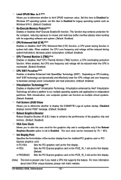
... during system halt state to display the GIGABYTE Logo at system startup. The core clock can dynamically and effectively lower the CPU voltage and core frequency to enhance the performance of the monitor display from the installed PCI graphics card or PCI Express graphics card. GA-N650SLI-DS4L Motherboard - 42 - This function may enhance...
... during system halt state to display the GIGABYTE Logo at system startup. The core clock can dynamically and effectively lower the CPU voltage and core frequency to enhance the performance of the monitor display from the installed PCI graphics card or PCI Express graphics card. GA-N650SLI-DS4L Motherboard - 42 - This function may enhance...


