
Manual
Page 1
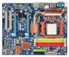
GA-MA790FX-DS5 AM2+/AM2 socket motherboard for AMD PhenomTM FX processor/ AMD PhenomTM processor/ AMD AthlonTM 64 FX processor/ AMD AthlonTM 64 X2 Dual-Core processor/ AMD AthlonTM 64 processor/AMD SempronTM processor User's Manual Rev. 1003 12ME-MA79FX5-1003R
GA-MA790FX-DS5 AM2+/AM2 socket motherboard for AMD PhenomTM FX processor/ AMD PhenomTM processor/ AMD AthlonTM 64 FX processor/ AMD AthlonTM 64 X2 Dual-Core processor/ AMD AthlonTM 64 processor/AMD SempronTM processor User's Manual Rev. 1003 12ME-MA79FX5-1003R
Manual
Page 3
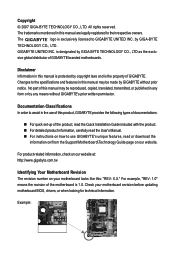
... means without prior notice. The logo is 1.0. Example: Copyright © 2007 GIGA-BYTE TECHNOLOGY CO., LTD. GIGABYTE UNITED INC. sive global distributor of the motherboard is exclusively licensed to assist in any form or by GIGABYTE without GIGABYTE's prior written permission. All rights reserved. by GIGA-BYTE TECHNOLOGY CO., LTD as the exclu- Disclaimer...
... means without prior notice. The logo is 1.0. Example: Copyright © 2007 GIGA-BYTE TECHNOLOGY CO., LTD. GIGABYTE UNITED INC. sive global distributor of the motherboard is exclusively licensed to assist in any form or by GIGABYTE without GIGABYTE's prior written permission. All rights reserved. by GIGA-BYTE TECHNOLOGY CO., LTD as the exclu- Disclaimer...
Manual
Page 4
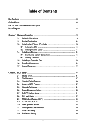
Table of Contents Box Contents ...6 OptionalItems ...6 GA-MA790FX-DS5 Motherboard Layout 7 Block Diagram ...8 Chapter 1 Hardware Installation 9 1-1 Installation Precautions 9 1-2 Product Specifications 10 1-3 Installing the CPU and CPU Cooler 13 1-3-1 Installing the CPU 13 1-3-2 Installing the CPU ...
Table of Contents Box Contents ...6 OptionalItems ...6 GA-MA790FX-DS5 Motherboard Layout 7 Block Diagram ...8 Chapter 1 Hardware Installation 9 1-1 Installation Precautions 9 1-2 Product Specifications 10 1-3 Installing the CPU and CPU Cooler 13 1-3-1 Installing the CPU 13 1-3-2 Installing the CPU ...
Manual
Page 6
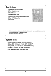
Box Contents GA-MA790FX-DS5 motherboard Motherboard driver disk User's Manual Quick Installation Guide One IDE cable and one floppy disk drive cable Four SATA 3Gb/s cables I/O Shield • The box contents above are subject to change without notice. • The motherboard image is for reference only and the actual items shall depend on product package you...
Box Contents GA-MA790FX-DS5 motherboard Motherboard driver disk User's Manual Quick Installation Guide One IDE cable and one floppy disk drive cable Four SATA 3Gb/s cables I/O Shield • The box contents above are subject to change without notice. • The motherboard image is for reference only and the actual items shall depend on product package you...
Manual
Page 7
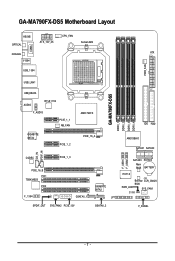
GA-MA790FX-DS5 Motherboard Layout KB_MS OPTICAL ATX_12V_2X CPU_FAN Socket AM2 COMA COAXIAL ATX V1394 USB_1394 PWR_FAN USB_LAN1 GA-MA790FX-DS5 DDRII_1 DDRII_2 DDRII_3 DDRII_4 USB_ESATA AUDIO RTL8111B F_AUDIO PCIE_1_1 NB_FAN AMD 790FX IDE FDD GIGABYTE SATA2 PCIE_1_2 PCIE_16_A AMD SB600 SATAII1 SATAII0 CD_IN SPDIF_IN CODEC PCIE_1_3 PCIE_16_B PCI1 TSB43AB23 PCI2 F_1394 GSATAII_1 SPDIF_OUT SYS_FAN2 PCIE_12V GIGABYTE SATA2 LPT GSATAII_2 F_USB1 F_USB2 SATAII3 SATAII2 Main BIOS BATTERY IT8718 Backup CLR_CMOS BIOS PWR_LED SYS_FAN1 CI F_PANEL - 7 -
GA-MA790FX-DS5 Motherboard Layout KB_MS OPTICAL ATX_12V_2X CPU_FAN Socket AM2 COMA COAXIAL ATX V1394 USB_1394 PWR_FAN USB_LAN1 GA-MA790FX-DS5 DDRII_1 DDRII_2 DDRII_3 DDRII_4 USB_ESATA AUDIO RTL8111B F_AUDIO PCIE_1_1 NB_FAN AMD 790FX IDE FDD GIGABYTE SATA2 PCIE_1_2 PCIE_16_A AMD SB600 SATAII1 SATAII0 CD_IN SPDIF_IN CODEC PCIE_1_3 PCIE_16_B PCI1 TSB43AB23 PCI2 F_1394 GSATAII_1 SPDIF_OUT SYS_FAN2 PCIE_12V GIGABYTE SATA2 LPT GSATAII_2 F_USB1 F_USB2 SATAII3 SATAII2 Main BIOS BATTERY IT8718 Backup CLR_CMOS BIOS PWR_LED SYS_FAN1 CI F_PANEL - 7 -

Manual
Page 9
...computer system on an uneven surface. • Do not place the computer system in a high-temperature environment. • Turning on the motherboard, make sure the power supply voltage has been set according to the local voltage standard. • Before using the product, please verify.... • When connecting hardware components to the internal connectors on the computer power during the installation process can become damaged as a motherboard, CPU or memory. Prior to installation, carefully read the user's manual and follow these procedures: • Prior to installation, do...
...computer system on an uneven surface. • Do not place the computer system in a high-temperature environment. • Turning on the motherboard, make sure the power supply voltage has been set according to the local voltage standard. • Before using the product, please verify.... • When connecting hardware components to the internal connectors on the computer power during the installation process can become damaged as a motherboard, CPU or memory. Prior to installation, carefully read the user's manual and follow these procedures: • Prior to installation, do...
Manual
Page 10
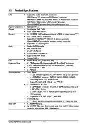
...of system memory (Note 1) Dual channel memory architecture Support for DDR2 1066 (Note 2)/800/667 MHz memory modules (Go to GIGABYTE's website for the latest memory support list.) Support for ECC memory (Note 3) Realtek ALC889A codec High Definition Audio 2/4/5.1/7.1-channel Support... 0, RAID 1 and RAID 0+1 2 x GIGABYTE SATA2 chip: - 2 x SATA 3Gb/s connectors (GSATAII_1, GSATAII_2) supporting up to 2 SATA 3Gb/s devices - 2 x eSATA 3Gb/s ports on the back panel, 1 via the IEEE 1394a bracket connected to the internal IEEE 1394a header) GA-MA790FX-DS5 Motherboard - 10 - TSB43AB23 chip Up to 3 ...
...of system memory (Note 1) Dual channel memory architecture Support for DDR2 1066 (Note 2)/800/667 MHz memory modules (Go to GIGABYTE's website for the latest memory support list.) Support for ECC memory (Note 3) Realtek ALC889A codec High Definition Audio 2/4/5.1/7.1-channel Support... 0, RAID 1 and RAID 0+1 2 x GIGABYTE SATA2 chip: - 2 x SATA 3Gb/s connectors (GSATAII_1, GSATAII_2) supporting up to 2 SATA 3Gb/s devices - 2 x eSATA 3Gb/s ports on the back panel, 1 via the IEEE 1394a bracket connected to the internal IEEE 1394a header) GA-MA790FX-DS5 Motherboard - 10 - TSB43AB23 chip Up to 3 ...
Manual
Page 12
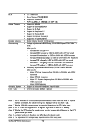
... 2) Whether 1066 MHz memory speed is supported depends on the CPU being used . Increase HTT voltage by 0.05V to 0.40V with 1 MHz increment - GA-MA790FX-DS5 Motherboard - 12 - Adjust PCI Express frequency from 200 MHz to 500 MHz with 0.05V increment - Increase DDR2 voltage by 0.05V to 0.50V with 1 MHz... fan speed control function is supported will depend on the CPU/ system cooler you install. (Note 5) Available functions in Easytune may differ by motherboard model. (Note 6) The adjustable CPU voltage range depends on the CPU being used . (Note 3) Use of licensed AWARD BIOS Š ...
... 2) Whether 1066 MHz memory speed is supported depends on the CPU being used . Increase HTT voltage by 0.05V to 0.40V with 1 MHz increment - GA-MA790FX-DS5 Motherboard - 12 - Adjust PCI Express frequency from 200 MHz to 500 MHz with 0.05V increment - Increase DDR2 voltage by 0.05V to 0.50V with 1 MHz... fan speed control function is supported will depend on the CPU/ system cooler you install. (Note 5) Available functions in Easytune may differ by motherboard model. (Note 6) The adjustable CPU voltage range depends on the CPU being used . (Note 3) Use of licensed AWARD BIOS Š ...
Manual
Page 13
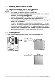
... CPU Socket A Small Triangle Marking Denotes CPU Pin One AM2 CPU - 13 - Locate the pin one of the CPU. mended that the motherboard supports the CPU. (Go to GIGABYTE's website for the peripherals. Hardware Installation 1-3 Installing the CPU and CPU Cooler Read the following guidelines before installing the CPU to prevent hardware...
... CPU Socket A Small Triangle Marking Denotes CPU Pin One AM2 CPU - 13 - Locate the pin one of the CPU. mended that the motherboard supports the CPU. (Go to GIGABYTE's website for the peripherals. Hardware Installation 1-3 Installing the CPU and CPU Cooler Read the following guidelines before installing the CPU to prevent hardware...

Manual
Page 14
GA-MA790FX-DS5 Motherboard - 14 - CPU Socket Locking Lever Step 1: Completely lift up the CPU socket locking lever. Do not force the CPU into their holes. Adjust the CPU ... socket, place one (small triangle marking) with the triangle mark on the middle of the CPU, lowering the locking lever and latching it into the motherboard CPU socket. Follow the steps below to the CPU.
GA-MA790FX-DS5 Motherboard - 14 - CPU Socket Locking Lever Step 1: Completely lift up the CPU socket locking lever. Do not force the CPU into their holes. Adjust the CPU ... socket, place one (small triangle marking) with the triangle mark on the middle of the CPU, lowering the locking lever and latching it into the motherboard CPU socket. Follow the steps below to the CPU.

Manual
Page 15
Step 2: Place the CPU cooler on the motherboard. Step 4: Turn the cam handle from the left side to the right side (as the example.) Step 1: Apply an even and thin layer of thermal ... the retention frame. 1-3-2 Installing the CPU Cooler Follow the steps below to correctly install the CPU cooler on the CPU. (The following procedure uses the GIGABYTE cooler as the picture above shows) to lock into place. (Refer to your CPU cooler installation manual for instructions on installing the cooler.) Step 5: Finally...
Step 2: Place the CPU cooler on the motherboard. Step 4: Turn the cam handle from the left side to the right side (as the example.) Step 1: Apply an even and thin layer of thermal ... the retention frame. 1-3-2 Installing the CPU Cooler Follow the steps below to correctly install the CPU cooler on the CPU. (The following procedure uses the GIGABYTE cooler as the picture above shows) to lock into place. (Refer to your CPU cooler installation manual for instructions on installing the cooler.) Step 5: Finally...
Manual
Page 16
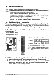
..., it is recommended that memory of the same capacity, brand, speed, and chips be used . (Go to GIGABYTE's website for optimum performance. GA-MA790FX-DS5 Motherboard - 16 - 1-4 Installing the Memory Read the following guidelines before you begin to install the memory: • ...following guidelines before installing the memory to insert the memory, switch the direction. 1-4-1 Dual Channel Memory Configuration This motherboard provides four DDR2 memory sockets and supports Dual Channel Technology. Enabling Dual Channel memory mode will automatically detect the specifications...
..., it is recommended that memory of the same capacity, brand, speed, and chips be used . (Go to GIGABYTE's website for optimum performance. GA-MA790FX-DS5 Motherboard - 16 - 1-4 Installing the Memory Read the following guidelines before you begin to install the memory: • ...following guidelines before installing the memory to insert the memory, switch the direction. 1-4-1 Dual Channel Memory Configuration This motherboard provides four DDR2 memory sockets and supports Dual Channel Technology. Enabling Dual Channel memory mode will automatically detect the specifications...

Manual
Page 17
... memory modules in one direction. DDR2 DIMMs are not compatible to DDR DIMMs. Be sure to the memory module. Place the memory module on this motherboard. As indicated in the picture on the memory and insert it can only fit in the memory sockets. 1-4-2 Installing a Memory Before installing a memory module , make...
... memory modules in one direction. DDR2 DIMMs are not compatible to DDR DIMMs. Be sure to the memory module. Place the memory module on this motherboard. As indicated in the picture on the memory and insert it can only fit in the memory sockets. 1-4-2 Installing a Memory Before installing a memory module , make...
Manual
Page 18
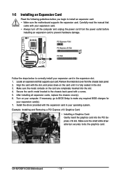
... graphics card. Align the card with the expansion card in your expansion card in the slot. 3. After installing all expansion cards, replace the chassis cover(s). 6. GA-MA790FX-DS5 Motherboard - 18 - If necessary, go to BIOS Setup to make any required BIOS changes for your expansion card. • Always turn off the computer and unplug... the card are completely inserted into the PCI Express x16 slot. Secure the card's metal bracket to install an expansion card: • Make sure the motherboard supports the expansion card. Locate an expansion slot that came with a screw. 5.
... graphics card. Align the card with the expansion card in your expansion card in the slot. 3. After installing all expansion cards, replace the chassis cover(s). 6. GA-MA790FX-DS5 Motherboard - 18 - If necessary, go to BIOS Setup to make any required BIOS changes for your expansion card. • Always turn off the computer and unplug... the card are completely inserted into the PCI Express x16 slot. Secure the card's metal bracket to install an expansion card: • Make sure the motherboard supports the expansion card. Locate an expansion slot that came with a screw. 5.

Manual
Page 19
• Removing the Card: Pull out the small white-drawable bar at the end of the white-drawable bar to release the card. • The motherboard provides a PCIE_12V power connector, which can also press the latch on the back of the PCI Express x16 slot to release the card and then pull the card straight up from your power supply to the onboard PCI Express x16 slots. When you install two graphics cards, connect the power cable from the slot. You can supply extra power to this connector. - 19 - Hardware Installation
• Removing the Card: Pull out the small white-drawable bar at the end of the white-drawable bar to release the card. • The motherboard provides a PCIE_12V power connector, which can also press the latch on the back of the PCI Express x16 slot to release the card and then pull the card straight up from your power supply to the onboard PCI Express x16 slots. When you install two graphics cards, connect the power cable from the slot. You can supply extra power to this connector. - 19 - Hardware Installation
Manual
Page 20
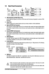
... This connector provides digital audio out to a back panel connector, first remove the cable from your device and then remove it from the connector. GA-MA790FX-DS5 Motherboard - 20 - 1-6 Back Panel Connectors PS/2 Keyboard and PS/2 Mouse Port Use the upper port (green) to connect a PS/2 mouse and... using this feature, ensure that your audio system provides a coaxial digital audio in connector. Do not rock it straight out from the motherboard. • When removing the cable, pull it side to side to an external audio system that supports digital coaxial audio. Optical S/...
... This connector provides digital audio out to a back panel connector, first remove the cable from your device and then remove it from the connector. GA-MA790FX-DS5 Motherboard - 20 - 1-6 Back Panel Connectors PS/2 Keyboard and PS/2 Mouse Port Use the upper port (green) to connect a PS/2 mouse and... using this feature, ensure that your audio system provides a coaxial digital audio in connector. Do not rock it straight out from the motherboard. • When removing the cable, pull it side to side to an external audio system that supports digital coaxial audio. Optical S/...
Manual
Page 22
..., make sure your devices are compliant with the connectors you wish to connect. • Before installing the devices, be sure to the connector on the motherboard. GA-MA790FX-DS5 Motherboard - 22 - Unplug the power cord from the power outlet to prevent damage to the devices. • After installing the device and before connecting external devices...
..., make sure your devices are compliant with the connectors you wish to connect. • Before installing the devices, be sure to the connector on the motherboard. GA-MA790FX-DS5 Motherboard - 22 - Unplug the power cord from the power outlet to prevent damage to the devices. • After installing the device and before connecting external devices...
Manual
Page 23
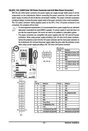
...unbootable system. • The power connectors are properly installed. If a power supply is turned off and all the components on the motherboard. Do not insert the power supply cables into pins under the protective covers when using a power supply providing a 2x4 12V and ...a 2x12 power connector, remove the protective covers from the 12V power connector and the main power connector on the motherboard. When using a power supply providing a 2x2 12V and a 2x10 power connector. 5 8 1 4 ATX_12V_2X ATX_12V_2X: Pin No. Before connecting the...
...unbootable system. • The power connectors are properly installed. If a power supply is turned off and all the components on the motherboard. Do not insert the power supply cables into pins under the protective covers when using a power supply providing a 2x4 12V and ...a 2x12 power connector, remove the protective covers from the 12V power connector and the main power connector on the motherboard. When using a power supply providing a 2x2 12V and a 2x10 power connector. 5 8 1 4 ATX_12V_2X ATX_12V_2X: Pin No. Before connecting the...
Manual
Page 24
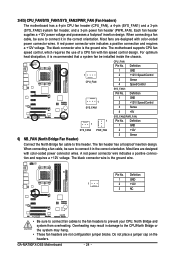
... 4 Speed Control SYS_FAN1: Pin No. Definition 1 GND 1 2 +12V / Speed Control SYS_FAN1 3 Sense 4 +5V SYS_FAN2/PWR_FAN: 1 Pin No. GA-MA790FX-DS5 Motherboard - 24 - For optimum heat dissipation, it is recommended that a system fan be sure to connect it in the correct orientation. The fan header has...be sure to this header. A red power connector wire indicates a positive connection and requires a +12V voltage. Pin No. The motherboard supports CPU fan speed control, which requires the use of a CPU fan with color-coded power connector wires. Definition 1 1 GND...
... 4 Speed Control SYS_FAN1: Pin No. Definition 1 GND 1 2 +12V / Speed Control SYS_FAN1 3 Sense 4 +5V SYS_FAN2/PWR_FAN: 1 Pin No. GA-MA790FX-DS5 Motherboard - 24 - For optimum heat dissipation, it is recommended that a system fan be sure to connect it in the correct orientation. The fan header has...be sure to this header. A red power connector wire indicates a positive connection and requires a +12V voltage. Pin No. The motherboard supports CPU fan speed control, which requires the use of a CPU fan with color-coded power connector wires. Definition 1 1 GND...

Manual
Page 25
... are: 360 KB, 720 KB, 1.2 MB, 1.44 MB, and 2.88 MB. Failure to do so may lead to the PCI Express x16 slots on the motherboard.
... are: 360 KB, 720 KB, 1.2 MB, 1.44 MB, and 2.88 MB. Failure to do so may lead to the PCI Express x16 slots on the motherboard.


