Manual
Page 1
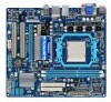
GA-MA78LMT-S2H/ GA-MA78LMT-S2 AM3 socket motherboard for AMD Phenom™ II processor/ AMD Athlon™ II processor User's Manual Rev. 1001 12ME-MA78LT2-1001R
GA-MA78LMT-S2H/ GA-MA78LMT-S2 AM3 socket motherboard for AMD Phenom™ II processor/ AMD Athlon™ II processor User's Manual Rev. 1001 12ME-MA78LT2-1001R
Manual
Page 3
... In order to the specifications and features in this manual may be made by copyright laws and is the property of GIGABYTE. No part of documentations: For detailed product information, carefully read the User's Manual. For instructions on how to their respective...© 2009 GIGA-BYTE TECHNOLOGY CO., LTD. Check your motherboard looks like this product, GIGABYTE provides the following types of this manual are legally registered to use GIGABYTE's unique features, read or download the information on/from the Support&Downloads\Motherboard\Technology Guide ...
... In order to the specifications and features in this manual may be made by copyright laws and is the property of GIGABYTE. No part of documentations: For detailed product information, carefully read the User's Manual. For instructions on how to their respective...© 2009 GIGA-BYTE TECHNOLOGY CO., LTD. Check your motherboard looks like this product, GIGABYTE provides the following types of this manual are legally registered to use GIGABYTE's unique features, read or download the information on/from the Support&Downloads\Motherboard\Technology Guide ...
Manual
Page 5
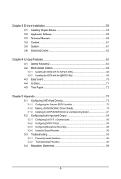
Chapter 3 Drivers Installation 59 3-1 Installing Chipset Drivers 59 3-2 Application Software 60 3-3 Technical Manuals 60 3-4 Contact...61 3-5 System...61 3-6 Download Center 62 Chapter 4 Unique Features 63 4-1 Xpress Recovery2 63 4-2 BIOS Update Utilities 66 4-2-1 Updating the BIOS with the Q-Flash ...
Chapter 3 Drivers Installation 59 3-1 Installing Chipset Drivers 59 3-2 Application Software 60 3-3 Technical Manuals 60 3-4 Contact...61 3-5 System...61 3-6 Download Center 62 Chapter 4 Unique Features 63 4-1 Xpress Recovery2 63 4-2 BIOS Update Utilities 66 4-2-1 Updating the BIOS with the Q-Flash ...
Manual
Page 6
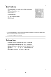
... No. 12CF1-2SERPW-0*R) S/PDIF In and Out cable (Part No. 12CR1-1SPINO-1*R) COM port cable (Part No. 12CF1-1CM001-3*R) - 6 - Box Contents GA-MA78LMT-S2H or GA-MA78LMT-S2 motherboard Motherboard driver disk User's Manual One IDE cable Two SATA 3Gb/s cables I/O Shield • The box contents above are subject to change without notice. • The motherboard...
... No. 12CF1-2SERPW-0*R) S/PDIF In and Out cable (Part No. 12CR1-1SPINO-1*R) COM port cable (Part No. 12CF1-1CM001-3*R) - 6 - Box Contents GA-MA78LMT-S2H or GA-MA78LMT-S2 motherboard Motherboard driver disk User's Manual One IDE cable Two SATA 3Gb/s cables I/O Shield • The box contents above are subject to change without notice. • The motherboard...
Manual
Page 9
... uncertain about any installation steps or have a problem related to the use of electrostatic discharge (ESD). Hardware Installation Prior to installation, carefully read the user's manual and follow these procedures: • Prior to wear an electrostatic discharge (ESD) wrist strap when handling electronic com- ponents such as a motherboard, CPU or memory...
... uncertain about any installation steps or have a problem related to the use of electrostatic discharge (ESD). Hardware Installation Prior to installation, carefully read the user's manual and follow these procedures: • Prior to wear an electrostatic discharge (ESD) wrist strap when handling electronic com- ponents such as a motherboard, CPU or memory...
Manual
Page 15
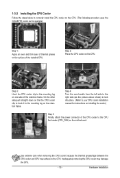
... the steps below to correctly install the CPU cooler on the CPU. (The following procedure uses the GIGABYTE cooler as the picture above shows) to lock into place. (Refer to your CPU cooler installation manual for instructions on installing the cooler.) Step 5: Finally, attach the power connector of the CPU cooler to...
... the steps below to correctly install the CPU cooler on the CPU. (The following procedure uses the GIGABYTE cooler as the picture above shows) to lock into place. (Refer to your CPU cooler installation manual for instructions on installing the cooler.) Step 5: Finally, attach the power connector of the CPU cooler to...
Manual
Page 18
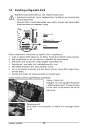
... with the expansion card in your expansion card in the expansion slot. 1. Make sure the card is securely seated in the slot. 3. Carefully read the manual that supports your computer. Make sure the metal contacts on your card. Install the driver provided with the slot, and press down on the top...
... with the expansion card in your expansion card in the expansion slot. 1. Make sure the card is securely seated in the slot. 3. Carefully read the manual that supports your computer. Make sure the metal contacts on your card. Install the driver provided with the slot, and press down on the top...
Manual
Page 28
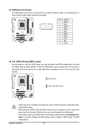
... do so may cause damage to the motherboard. • After system restart, go to BIOS Setup to load factory defaults (select Load Optimized Defaults) or manually configure the BIOS settings (refer to factory defaults. Open: Normal Short: Clear CMOS Values • Always turn off your computer and unplug the power cord...
... do so may cause damage to the motherboard. • After system restart, go to BIOS Setup to load factory defaults (select Load Optimized Defaults) or manually configure the BIOS settings (refer to factory defaults. Open: Normal Short: Clear CMOS Values • Always turn off your computer and unplug the power cord...

Manual
Page 36
...: Optimized Defaults EC Firmware Selection Allows you to All Cores. A message which says "BIOS Is Updating EC Firmware!!! tion CPU. Manual allows the two items below to enable Advanced Clock Calibration when using an AMD Black Edi- Normal Uses the standard AMD EC firmware ... (Note) This item appears only if you to determine whether to be configurable. Disabled Disables this feature. Options are : Auto (default), Manual. Manual Allows you to determine whether to All Cores. Options are: -12%~+12%. Don't Turn Off Or Reset System" will automatically restart for ...
...: Optimized Defaults EC Firmware Selection Allows you to All Cores. A message which says "BIOS Is Updating EC Firmware!!! tion CPU. Manual allows the two items below to enable Advanced Clock Calibration when using an AMD Black Edi- Normal Uses the standard AMD EC firmware ... (Note) This item appears only if you to determine whether to be configurable. Disabled Disables this feature. Options are : Auto (default), Manual. Manual Allows you to determine whether to All Cores. Options are: -12%~+12%. Don't Turn Off Or Reset System" will automatically restart for ...
Manual
Page 37
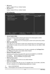
...display. VGA Core Clock control Enables or disables the control of VGA Core clock. (Default: Disabled) VGA Core Clock(MHz) Allows you to manually set to PEG and an ATI graphics card is set the VGA Core clock. This item is configurable only if the VGA Core Clock control...allocated solely for the onboard graphics con- BIOS Setup UMA Allocates memory for the onboard graphics controller from 200 MHz to allocate system memory for GA-MA78LMT-S2H (Note) This item appears only if you to determine whether to 2000 MHz. j Only for the onboard graphics controller. Disabled Disables the...
...display. VGA Core Clock control Enables or disables the control of VGA Core clock. (Default: Disabled) VGA Core Clock(MHz) Allows you to manually set to PEG and an ATI graphics card is set the VGA Core clock. This item is configurable only if the VGA Core Clock control...allocated solely for the onboard graphics con- BIOS Setup UMA Allocates memory for the onboard graphics controller from 200 MHz to allocate system memory for GA-MA78LMT-S2H (Note) This item appears only if you to determine whether to 2000 MHz. j Only for the onboard graphics controller. Disabled Disables the...
Manual
Page 38
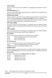
...Bridge controller frequency for the HT Link between the CPU and chipset. X5.33 X6.66 X8.00 Sets Memory Clock to be configurable. Manual allows the CPU Frequency (MHz) item below to be set the PCIe clock frequency. The adjustable range is set the width for the ...on the CPU being used . Auto BIOS will automatically adjust the HT Link Frequency. (Default) 200 MHz~2.6 GHz Sets HT Link Frequency to manually set the memory clock as required. Auto lets BIOS automatically set the memory clock. Sets Memory Clock to 16 bit. Sets Memory Clock to X8...
...Bridge controller frequency for the HT Link between the CPU and chipset. X5.33 X6.66 X8.00 Sets Memory Clock to be configurable. Manual allows the CPU Frequency (MHz) item below to be set the PCIe clock frequency. The adjustable range is set the width for the ...on the CPU being used . Auto BIOS will automatically adjust the HT Link Frequency. (Default) 200 MHz~2.6 GHz Sets HT Link Frequency to manually set the memory clock as required. Auto lets BIOS automatically set the memory clock. Sets Memory Clock to 16 bit. Sets Memory Clock to X8...
Manual
Page 39
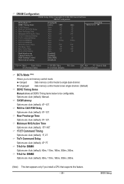
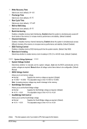
Unganged Sets memory control mode to two single-channel. (Default) DDR3 Timing Items Manual allows all DDR3 Timing items below to single dual-channel. BIOS Setup DRAM Configuration CMOS Setup Utility-Copyright (C) 1984-2009 Award Software DRAM Configuration DCTs... - 39 - Options are : Auto (default), 1T, 2T. Minimum RAS Active Time Options are: Auto (default), 15T~30T. 1T/2T Command Timing Options are : Auto (default), Manual. TwTr Command Delay Options are : Auto (default), 5T~12T. Row Precharge Time Options are : Auto (default), 4T~7T. Trfc2 for DIMM1 Options are : Auto (default...
Unganged Sets memory control mode to two single-channel. (Default) DDR3 Timing Items Manual allows all DDR3 Timing items below to single dual-channel. BIOS Setup DRAM Configuration CMOS Setup Utility-Copyright (C) 1984-2009 Award Software DRAM Configuration DCTs... - 39 - Options are : Auto (default), 1T, 2T. Minimum RAS Active Time Options are: Auto (default), 15T~30T. 1T/2T Command Timing Options are : Auto (default), Manual. TwTr Command Delay Options are : Auto (default), 5T~12T. Row Precharge Time Options are : Auto (default), 4T~7T. Trfc2 for DIMM1 Options are : Auto (default...
Manual
Page 40
.... BIOS Setup - 40 - RAS to +0.300V. SouthBridge Volt Control Allows you to set the North Bridge voltage. Manual allows all voltage control items below to be configurable. (Default: Manual) DDR3 Voltage Control Allows you to set memory voltage. NorthBridge Volt Control Allows you install a CPU that supports this ...), 11T~42T. Precharge Time Options are : Auto (default), 4T~7T. Enabled allows the system to simultaneously access different channels of the memory to manually set the South Bridge voltage. Normal Supplies the North Bridge voltage as required.
.... BIOS Setup - 40 - RAS to +0.300V. SouthBridge Volt Control Allows you to set the North Bridge voltage. Manual allows all voltage control items below to be configurable. (Default: Manual) DDR3 Voltage Control Allows you to set memory voltage. NorthBridge Volt Control Allows you install a CPU that supports this ...), 11T~42T. Precharge Time Options are : Auto (default), 4T~7T. Enabled allows the system to simultaneously access different channels of the memory to manually set the South Bridge voltage. Normal Supplies the North Bridge voltage as required.
Manual
Page 43
... of floppy disk drive installed in your hard drive specifications. Typically, 640 KB will stop . BIOS Setup Drive A Allows you wish to enter the parameters manually, refer to select the type of the currently installed hard drive. The following fields display your system. If you to the information on the hard...
... of floppy disk drive installed in your hard drive specifications. Typically, 640 KB will stop . BIOS Setup Drive A Allows you wish to enter the parameters manually, refer to select the type of the currently installed hard drive. The following fields display your system. If you to the information on the hard...
Manual
Page 45
... a device and press to PEG and an ATI graphics card is the total amount of loading the operating system from the available devices. j Only for GA-MA78LMT-S2H (Note) This item appears only if you to manually set to accept.
... a device and press to PEG and an ATI graphics card is the total amount of loading the operating system from the available devices. j Only for GA-MA78LMT-S2H (Note) This item appears only if you to manually set to accept.

Manual
Page 59
... Chipset Drivers After inserting the driver disk, "Xpress Install" will automatically scan your system automatically during the driver installation. Or click Install Single Items to manually select the drivers you wish to do so may affect the driver installation. • Some device drivers will restart your system and then list all...
... Chipset Drivers After inserting the driver disk, "Xpress Install" will automatically scan your system automatically during the driver installation. Or click Install Single Items to manually select the drivers you wish to do so may affect the driver installation. • Some device drivers will restart your system and then list all...
Manual
Page 60
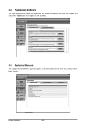
You can click the Install button on the right of an item to install it. 3-3 Technical Manuals This page provides GIGABYTE's application guides, content descriptions for this driver disk, and the motherboard manuals. Drivers Installation - 60 - 3-2 Application Software This page displays all the utilities and applications that GIGABYTE develops and some free software.
You can click the Install button on the right of an item to install it. 3-3 Technical Manuals This page provides GIGABYTE's application guides, content descriptions for this driver disk, and the motherboard manuals. Drivers Installation - 60 - 3-2 Application Software This page displays all the utilities and applications that GIGABYTE develops and some free software.

Manual
Page 66
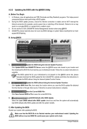
...press the key to -use and allow you can access Q-Flash by adding one more physical BIOS chip. GA-MA78LMT-S2H F1b . . . . : BIOS Setup : XpressRecovery2 : Boot Menu : Qflash 11/13/2009-...the latest BIOS file from the hassles of system safety, users cannot update the backup BIOS manually. Before You Begin 1. Motherboards that matches your floppy disk, USB flash drive, or hard..., please do it with the Q-Flash Utility A. Unique Features - 66 - 4-2 BIOS Update Utilities GIGABYTE motherboards provide two unique BIOS update tools, Q-Flash™ and @BIOS™. Normally, the system ...
...press the key to -use and allow you can access Q-Flash by adding one more physical BIOS chip. GA-MA78LMT-S2H F1b . . . . : BIOS Setup : XpressRecovery2 : Boot Menu : Qflash 11/13/2009-...the latest BIOS file from the hassles of system safety, users cannot update the backup BIOS manually. Before You Begin 1. Motherboards that matches your floppy disk, USB flash drive, or hard..., please do it with the Q-Flash Utility A. Unique Features - 66 - 4-2 BIOS Update Utilities GIGABYTE motherboards provide two unique BIOS update tools, Q-Flash™ and @BIOS™. Normally, the system ...
Manual
Page 69
... to do NOT interrupt the Internet connection (for your motherboard is not present on the @BIOS server site, please manually download the BIOS update file from GIGABYTE Server, select the @BIOS server site closest to your location and then download the BIOS file that the BIOS file... programs. This helps prevent unexpected failures when performing a BIOS update. 2. Update the BIOS Using the Internet Update Function: Click Update BIOS from GIGABYTE's website and follow the instructions in a corrupted BIOS or a system that is stable and do so may result in "Update the BIOS without...
... to do NOT interrupt the Internet connection (for your motherboard is not present on the @BIOS server site, please manually download the BIOS update file from GIGABYTE Server, select the @BIOS server site closest to your location and then download the BIOS file that the BIOS file... programs. This helps prevent unexpected failures when performing a BIOS update. 2. Update the BIOS Using the Internet Update Function: Click Update BIOS from GIGABYTE's website and follow the instructions in a corrupted BIOS or a system that is stable and do so may result in "Update the BIOS without...
Manual
Page 76
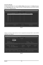
... LD 8 ---- Option ROM Utility (c) 2008 Advanced Micro Devices, Inc. LD 2 ---- LD 9 ---- LD 7 ---- LD 4 ---- Create Arrays Manually To create a new array, press to enter the RAID configuration menu (Figure 5). Option ROM Utility (c) 2008 Advanced Micro Devices, Inc. [ Define LD... LD 1 ---- LD No RAID Mode [ Define LD Menu ] Total Drv LD 1 RAID 0 0 Stripe Block: 64 KB Gigabyte Boundary: ON [ Drives Assignments ] Channel:ID Drive Model 1:Mas WDC WD800JD-22LSA0 2:Mas WDC WD800JD-22LSA0 Capabilities SATA 3G SATA 3G...
... LD 8 ---- Option ROM Utility (c) 2008 Advanced Micro Devices, Inc. LD 2 ---- LD 9 ---- LD 7 ---- LD 4 ---- Create Arrays Manually To create a new array, press to enter the RAID configuration menu (Figure 5). Option ROM Utility (c) 2008 Advanced Micro Devices, Inc. [ Define LD... LD 1 ---- LD No RAID Mode [ Define LD Menu ] Total Drv LD 1 RAID 0 0 Stripe Block: 64 KB Gigabyte Boundary: ON [ Drives Assignments ] Channel:ID Drive Model 1:Mas WDC WD800JD-22LSA0 2:Mas WDC WD800JD-22LSA0 Capabilities SATA 3G SATA 3G...


