
Manual
Page 3
...: For detailed product information, carefully read the User's Manual. For instructions on how to use GIGABYTE's unique features, read or download the information on/from the Support&Downloads\Motherboard\Technology Guide page on your motherboard revision..., copied, translated, transmitted, or published in any form or by any means without prior notice. Changes to their respective owners. No part of GIGABYTE. For example, "REV: 1.0" means the revision of the motherboard is the property of this : "REV: X.X." Example: For product-related information...
...: For detailed product information, carefully read the User's Manual. For instructions on how to use GIGABYTE's unique features, read or download the information on/from the Support&Downloads\Motherboard\Technology Guide page on your motherboard revision..., copied, translated, transmitted, or published in any form or by any means without prior notice. Changes to their respective owners. No part of GIGABYTE. For example, "REV: 1.0" means the revision of the motherboard is the property of this : "REV: X.X." Example: For product-related information...
Manual
Page 5
.../AHCI Driver and Operating System 76 5-2 Configuring Audio Input and Output 80 5-2-1 Configuring 2/4/5.1/7.1-Channel Audio 80 5-2-2 Configuring S/PDIF In/Out 83 5-2-3 Configuring Microphone Recording 85 5-2-4 Using the Sound Recorder 87 5-3 Troubleshooting 88 5-3-1 Frequently Asked Questions 88 5-3-2 Troubleshooting Procedure 89 5-4 Regulatory Statements 91 - 5 -
.../AHCI Driver and Operating System 76 5-2 Configuring Audio Input and Output 80 5-2-1 Configuring 2/4/5.1/7.1-Channel Audio 80 5-2-2 Configuring S/PDIF In/Out 83 5-2-3 Configuring Microphone Recording 85 5-2-4 Using the Sound Recorder 87 5-3 Troubleshooting 88 5-3-1 Frequently Asked Questions 88 5-3-2 Troubleshooting Procedure 89 5-4 Regulatory Statements 91 - 5 -

Manual
Page 7
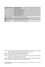
GA-MA78LM-S2H/GA-MA78LM-S2 Motherboard Layout DVI VGA KB(Note)_USB ATX_12V CPU_FAN Socket AM2 M_BIOS B_BIOS ATX IT8718 HDMIj R_USB USB IDE FDD LAN AUDIO F_AUDIO PCIEX1 AMD 760G DDR2_1 DDR2_2 PCIEX16 RTL8111D PCI1 GA-MA78LM-S2H/GA-MA78LM-S2 CD_IN CODEC PCI2 BAT AMD SB710 SATA2_0 COM SATA2_3 SATA2_2 SATA2_1 F_PANEL SPDIF_IO SYS_FAN CLR_CMOS F_USB2 F_USB1 j Only for GA-MA78LM-S2H (Note) Use this port to connect a PS/2 keyboard or PS/2 mouse. - 7 -
GA-MA78LM-S2H/GA-MA78LM-S2 Motherboard Layout DVI VGA KB(Note)_USB ATX_12V CPU_FAN Socket AM2 M_BIOS B_BIOS ATX IT8718 HDMIj R_USB USB IDE FDD LAN AUDIO F_AUDIO PCIEX1 AMD 760G DDR2_1 DDR2_2 PCIEX16 RTL8111D PCI1 GA-MA78LM-S2H/GA-MA78LM-S2 CD_IN CODEC PCI2 BAT AMD SB710 SATA2_0 COM SATA2_3 SATA2_2 SATA2_1 F_PANEL SPDIF_IO SYS_FAN CLR_CMOS F_USB2 F_USB1 j Only for GA-MA78LM-S2H (Note) Use this port to connect a PS/2 keyboard or PS/2 mouse. - 7 -

Manual
Page 9
... ESD wrist strap, keep your dealer. If you are uncertain about any metal leads or connectors. • It is best to the use of electrostatic discharge (ESD). These stickers are required for warranty validation. • Always remove the AC power by unplugging the power cord.... • Turning on the motherboard, make sure the power supply voltage has been set according to the local voltage standard. • Before using the product, please verify that all cables and power connectors of your hardware components are connected tightly and securely. • When handling the motherboard...
... ESD wrist strap, keep your dealer. If you are uncertain about any metal leads or connectors. • It is best to the use of electrostatic discharge (ESD). These stickers are required for warranty validation. • Always remove the AC power by unplugging the power cord.... • Turning on the motherboard, make sure the power supply voltage has been set according to the local voltage standard. • Before using the product, please verify that all cables and power connectors of your hardware components are connected tightly and securely. • When handling the motherboard...

Manual
Page 11
... detection CPU/System temperature detection CPU/System fan speed detection CPU overheating warning CPU/System fan fail warning CPU fan speed control (Note 5) 2 x 8 Mbit flash Use of licensed AWARD BIOS Support for DualBIOS™ PnP 1.0a, DMI 2.0, SM BIOS 2.4, ACPI 1.0b j Only for GA-MA78LM-S2H - 11 - Hardware Installation
... detection CPU/System temperature detection CPU/System fan speed detection CPU overheating warning CPU/System fan fail warning CPU fan speed control (Note 5) 2 x 8 Mbit flash Use of licensed AWARD BIOS Support for DualBIOS™ PnP 1.0a, DMI 2.0, SM BIOS 2.4, ACPI 1.0b j Only for GA-MA78LM-S2H - 11 - Hardware Installation
Manual
Page 12
... does not support D-Sub connection by adapter. (Note 3) Simultaneous output for DVI-D and HDMI is not supported. (Note 4) To configure 7.1-channel audio, you have to use an HD front panel audio module and enable themulti-channel audio feature through the audio driver. (Note 5) Whether the CPU fan speed control function is...
... does not support D-Sub connection by adapter. (Note 3) Simultaneous output for DVI-D and HDMI is not supported. (Note 4) To configure 7.1-channel audio, you have to use an HD front panel audio module and enable themulti-channel audio feature through the audio driver. (Note 5) Whether the CPU fan speed control function is...

Manual
Page 15
1-3-2 Installing the CPU Cooler Follow the steps below to correctly install the CPU cooler on the CPU. (The following procedure uses the GIGABYTE cooler as the picture above shows) to lock into place. (Refer to your CPU cooler installation manual for instructions on installing the cooler.) Step ...frame. Step 3: Hook the CPU cooler clip to the CPU. Inadequately removing the CPU cooler may adhere to the mounting lug on the motherboard. Use extreme care when removing the CPU cooler because the thermal grease/tape between the CPU cooler and CPU may damage the CPU. - 15 - ...
1-3-2 Installing the CPU Cooler Follow the steps below to correctly install the CPU cooler on the CPU. (The following procedure uses the GIGABYTE cooler as the picture above shows) to lock into place. (Refer to your CPU cooler installation manual for instructions on installing the cooler.) Step ...frame. Step 3: Hook the CPU cooler clip to the CPU. Inadequately removing the CPU cooler may adhere to the mounting lug on the motherboard. Use extreme care when removing the CPU cooler because the thermal grease/tape between the CPU cooler and CPU may damage the CPU. - 15 - ...

Manual
Page 16
When enabling Dual Channel mode with two memory modules, it is installed. 2. Dual Channel mode cannot be used . (Go to GIGABYTE's website for the latest memory support list.) • Always turn off the computer and unplug the power cord from the power outlet before... following : Channel 0: DDR2_1 Channel 1: DDR2_2 DDR2_1 DDR2_2 Due to prevent hardware damage. • Memory modules have a foolproof design. A memory module can be used . The two DDR2 memory sockets are unable to install the memory: • Make sure that memory of the memory. It is installed, the BIOS will...
When enabling Dual Channel mode with two memory modules, it is installed. 2. Dual Channel mode cannot be used . (Go to GIGABYTE's website for the latest memory support list.) • Always turn off the computer and unplug the power cord from the power outlet before... following : Channel 0: DDR2_1 Channel 1: DDR2_2 DDR2_1 DDR2_2 Due to prevent hardware damage. • Memory modules have a foolproof design. A memory module can be used . The two DDR2 memory sockets are unable to install the memory: • Make sure that memory of the memory. It is installed, the BIOS will...

Manual
Page 19
... Connectors (Note 1) (Note 2) (Note 2) j USB Port The USB port supports the USB 2.0/1.1 specification. Use this port for DVI-D and HDMI is not supported. - 19 - Hardware Installation j Only for GA-MA78LM-S2H (Note 1) The DVI-D port does not support D-Sub connection by adapter. (Note 2) Simultaneous output for USB...audio output only supports AC3, DTS and 2-channel-LPCM formats. (AC3 and DTS require the use of 1920x1080p but the actual resolutions supported depend on the monitor being used. • After installing the HDMI device, make sure the default device for decoding.) In ...
... Connectors (Note 1) (Note 2) (Note 2) j USB Port The USB port supports the USB 2.0/1.1 specification. Use this port for DVI-D and HDMI is not supported. - 19 - Hardware Installation j Only for GA-MA78LM-S2H (Note 1) The DVI-D port does not support D-Sub connection by adapter. (Note 2) Simultaneous output for USB...audio output only supports AC3, DTS and 2-channel-LPCM formats. (AC3 and DTS require the use of 1920x1080p but the actual resolutions supported depend on the monitor being used. • After installing the HDMI device, make sure the default device for decoding.) In ...

Manual
Page 20
... playing the HD DVD or Blu-ray discs, refer to Chapter 2, "BIOS Setup," "Advanced BIOS Features," for line in a 4/5.1-channel audio configuration. A. Microphones must be used to use an HD front panel audio module and enable themulti-channel audio feature through the audio driver...
... playing the HD DVD or Blu-ray discs, refer to Chapter 2, "BIOS Setup," "Advanced BIOS Features," for line in a 4/5.1-channel audio configuration. A. Microphones must be used to use an HD front panel audio module and enable themulti-channel audio feature through the audio driver...

Manual
Page 22
...not provide the required power, the result can lead to an unstable or unbootable system. • The main power connector is used that can withstand high power consumption be used (500W or greater). Connect the power supply cable to the CPU. 1/2) ATX_12V/ATX (2x2 12V Power Connector and 2x12 ...Main Power Connector) With the use of the power connector, the power supply can supply enough stable power to all devices are properly installed. The 12V power connector mainly supplies...
...not provide the required power, the result can lead to an unstable or unbootable system. • The main power connector is used that can withstand high power consumption be used (500W or greater). Connect the power supply cable to the CPU. 1/2) ATX_12V/ATX (2x2 12V Power Connector and 2x12 ...Main Power Connector) With the use of the power connector, the power supply can supply enough stable power to all devices are properly installed. The 12V power connector mainly supplies...

Manual
Page 23
...KB, 720 KB, 1.2 MB, 1.44 MB, and 2.88 MB. For optimum heat dissipation, it in the correct orientation (the black connector wire is used to the CPU or the system may result in damage to connect a floppy disk drive. Do not place a jumper cap on the headers. 5) FDD ... 33 2 1 - 23 - Hardware Installation The pin 1 of the connector and the floppy disk drive cable. The motherboard supports CPU fan speed control, which requires the use of different color. Definition 1 GND 2 +12V / Speed Control 3 Sense 4 Speed Control SYS_FAN: Pin No. 1 2 3 Definition GND +12V Sense • Be ...
...KB, 720 KB, 1.2 MB, 1.44 MB, and 2.88 MB. For optimum heat dissipation, it in the correct orientation (the black connector wire is used to the CPU or the system may result in damage to connect a floppy disk drive. Do not place a jumper cap on the headers. 5) FDD ... 33 2 1 - 23 - Hardware Installation The pin 1 of the connector and the floppy disk drive cable. The motherboard supports CPU fan speed control, which requires the use of different color. Definition 1 GND 2 +12V / Speed Control 3 Sense 4 Speed Control SYS_FAN: Pin No. 1 2 3 Definition GND +12V Sense • Be ...

Manual
Page 24
6) IDE (IDE Connector) The IDE connector supports up to be used, the total number of hard drives must be an even number. • A RAID 10 configuration requires at least two hard drives. Hardware Installation - 24 - The ...
6) IDE (IDE Connector) The IDE connector supports up to be used, the total number of hard drives must be an even number. • A RAID 10 configuration requires at least two hard drives. Hardware Installation - 24 - The ...

Manual
Page 25
... panel design may configure the way to turn off (S5). • PW (Power Switch, Red): Connects to the pin assignments below. When connecting your system using the power switch (refer to Chapter 2, "BIOS Setup," "Power Management Setup," for information about beep codes. • HD (Hard Drive Activity LED, Blue) Connects to...
... panel design may configure the way to turn off (S5). • PW (Power Switch, Red): Connects to the pin assignments below. When connecting your system using the power switch (refer to Chapter 2, "BIOS Setup," "Power Management Setup," for information about beep codes. • HD (Hard Drive Activity LED, Blue) Connects to...

Manual
Page 26
... panel audio module, refer to the instructions on both of the motherboard header. If you want to mute the back panel audio (only supported when using an HD front panel audio module), refer to Chapter 5, "Configuring 2/4/5.1/7.1-Channel Audio." • Some chassis provide a front panel audio module that came with your chassis...
... panel audio module, refer to the instructions on both of the motherboard header. If you want to mute the back panel audio (only supported when using an HD front panel audio module), refer to Chapter 5, "Configuring 2/4/5.1/7.1-Channel Audio." • Some chassis provide a front panel audio module that came with your chassis...

Manual
Page 28
... please contact the local dealer. To clear the CMOS values, place a jumper cap on the two pins to temporarily short the two pins or use a metal object like a screwdriver to remove the jumper cap from the power outlet before clearing the CMOS values. • After clearing the CMOS...from the jumper. Definition 1 NDCD- 2 10 2 NSIN 1 9 3 NSOUT 4 NDTR- 5 GND 6 NDSR- 7 NRTS- 8 NCTS- 9 NRI- 10 No Pin 14) CLR_CMOS (Clearing CMOS Jumper) Use this jumper to clear the CMOS values (e.g. 13) COM (Serial Port Header) The COM header can provide one serial port via an optional COM port...
... please contact the local dealer. To clear the CMOS values, place a jumper cap on the two pins to temporarily short the two pins or use a metal object like a screwdriver to remove the jumper cap from the power outlet before clearing the CMOS values. • After clearing the CMOS...from the jumper. Definition 1 NDCD- 2 10 2 NSIN 1 9 3 NSOUT 4 NDTR- 5 GND 6 NDSR- 7 NRTS- 8 NCTS- 9 NRI- 10 No Pin 14) CLR_CMOS (Clearing CMOS Jumper) Use this jumper to clear the CMOS values (e.g. 13) COM (Serial Port Header) The COM header can provide one serial port via an optional COM port...

Manual
Page 29
Hardware Installation You may be handled in accordance with an equivalent one minute. (Or use a metal object like a screwdriver to touch the positive and negative terminals of the battery holder, making them short for one . Replace the battery. 4. 15) BAT ...; When installing the battery, note the orientation of the positive side (+) and the negative side (-) of the battery (the positive side should face up). • Used batteries must be lost. Gently remove the battery from the battery holder and wait for 5 seconds.) 3. Danger of explosion if the battery is turned off...
Hardware Installation You may be handled in accordance with an equivalent one minute. (Or use a metal object like a screwdriver to touch the positive and negative terminals of the battery holder, making them short for one . Replace the battery. 4. 15) BAT ...; When installing the battery, note the orientation of the positive side (+) and the negative side (-) of the battery (the positive side should face up). • Used batteries must be lost. Gently remove the battery from the battery holder and wait for 5 seconds.) 3. Danger of explosion if the battery is turned off...
Manual
Page 31
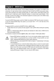
...Load Optimized Defaults" section in this chapter or introductions of the system in the CMOS on . To flash the BIOS, do not encounter problems using the Q-Flash and @BIOS utilities, refer to quickly and easily upgrade or back up BIOS without entering the operating system. • @BIOS ...features. To see more advanced BIOS Setup menu options, you do it is recommended that you not flash the BIOS. To upgrade the BIOS, use either the GIGABYTE Q-Flash or @BIOS utility. • Q-Flash allows the user to Chapter 4, "BIOS Update Utilities." • Because BIOS flashing is potentially...
...Load Optimized Defaults" section in this chapter or introductions of the system in the CMOS on . To flash the BIOS, do not encounter problems using the Q-Flash and @BIOS utilities, refer to quickly and easily upgrade or back up BIOS without entering the operating system. • @BIOS ...features. To see more advanced BIOS Setup menu options, you do it is recommended that you not flash the BIOS. To upgrade the BIOS, use either the GIGABYTE Q-Flash or @BIOS utility. • Q-Flash allows the user to Chapter 4, "BIOS Update Utilities." • Because BIOS flashing is potentially...

Manual
Page 32
2-1 Startup Screen The following screens may appear when the computer boots. You can be based on BIOS Setup settings. GA-MA78LM-S2H F1b . . . . : BIOS Setup : XpressRecovery2 : Boot Menu : Qflash 08/10/2009-RS780-SB710-7A66AG0NC-00 Function Keys Function Keys: : BIOS SETUP Press the...the device configured in Boot Menu is effective for subsequent access to enter BIOS Setup first. BIOS Setup - 32 - The system will still be used for one time only. Motherboard Model BIOS Version Award Modular BIOS v6.00PG, An Energy Star Ally Copyright (C) 1984-2009, Award Software, Inc....
2-1 Startup Screen The following screens may appear when the computer boots. You can be based on BIOS Setup settings. GA-MA78LM-S2H F1b . . . . : BIOS Setup : XpressRecovery2 : Boot Menu : Qflash 08/10/2009-RS780-SB710-7A66AG0NC-00 Function Keys Function Keys: : BIOS SETUP Press the...the device configured in Boot Menu is effective for subsequent access to enter BIOS Setup first. BIOS Setup - 32 - The system will still be used for one time only. Motherboard Model BIOS Version Award Modular BIOS v6.00PG, An Energy Star Ally Copyright (C) 1984-2009, Award Software, Inc....
Manual
Page 33
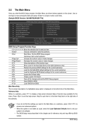
... BIOS default settings for the current submenus Load the Optimized BIOS default settings for the menu. Use arrow keys to move among the items and press to accept or enter a sub-menu. (Sample BIOS Version: GA-MA78LM-S2H F1b) CMOS Setup Utility-Copyright (C) 1984-2009 Award Software MB Intelligent Tweaker(M.I.T.) Standard CMOS...
... BIOS default settings for the current submenus Load the Optimized BIOS default settings for the menu. Use arrow keys to move among the items and press to accept or enter a sub-menu. (Sample BIOS Version: GA-MA78LM-S2H F1b) CMOS Setup Utility-Copyright (C) 1984-2009 Award Software MB Intelligent Tweaker(M.I.T.) Standard CMOS...

