
Manual
Page 9
... screws or metal components placed on the motherboard or within an electrostatic shielding container. • Before unplugging the power supply cable from the power outlet before installing or removing the motherboard or other hardware components. • When connecting hardware components to the internal...(Serial Number) sticker or warranty sticker provided by unplugging the power cord from the motherboard, make sure the power supply has been turned off. • Before turning on the motherboard, make sure the power supply voltage has been set according to the local voltage standard. &#...
... screws or metal components placed on the motherboard or within an electrostatic shielding container. • Before unplugging the power supply cable from the power outlet before installing or removing the motherboard or other hardware components. • When connecting hardware components to the internal...(Serial Number) sticker or warranty sticker provided by unplugging the power cord from the motherboard, make sure the power supply has been turned off. • Before turning on the motherboard, make sure the power supply voltage has been set according to the local voltage standard. &#...

Manual
Page 24
... (500W or greater). The 12V power connector mainly supplies power to the power connector in the correct orientation. When using a power supply providing a 2x2 12V and a 2x10 power connector. 1 5 4 8 ATX_12V_2X4 ATX_12V_2X4: Pin No. Connect the power supply cable to the CPU. Do not insert the power supply cables into pins under the protective covers when using a power supply providing a 2x4 12V and a 2x12...
... (500W or greater). The 12V power connector mainly supplies power to the power connector in the correct orientation. When using a power supply providing a 2x2 12V and a 2x10 power connector. 1 5 4 8 ATX_12V_2X4 ATX_12V_2X4: Pin No. Connect the power supply cable to the CPU. Do not insert the power supply cables into pins under the protective covers when using a power supply providing a 2x4 12V and a 2x12...

Manual
Page 25
... 1 GND 1 2 +12V 3 NC • Be sure to connect fan cables to the fan headers to this header. Each fan header supplies a +12V power voltage and possesses a foolproof insertion design. Do not place a jumper cap on the headers. - 25 - The black connector wire is the ground...fans are designed with fan speed control design. The motherboard supports CPU fan speed control, which requires the use of a CPU fan with colorcoded power connector wires. For optimum heat dissipation, it in damage to connect it in the correct orientation. Definition 1 CPU_FAN 1 GND 2 +12V ...
... 1 GND 1 2 +12V 3 NC • Be sure to connect fan cables to the fan headers to this header. Each fan header supplies a +12V power voltage and possesses a foolproof insertion design. Do not place a jumper cap on the headers. - 25 - The black connector wire is the ground...fans are designed with fan speed control design. The motherboard supports CPU fan speed control, which requires the use of a CPU fan with colorcoded power connector wires. For optimum heat dissipation, it in damage to connect it in the correct orientation. Definition 1 CPU_FAN 1 GND 2 +12V ...

Manual
Page 35
...the CMOS values and reset the board to default values. (Refer to activate certain system features. To upgrade the BIOS, use either the GIGABYTE Q-Flash or @BIOS utility. • Q-Flash allows the user to quickly and easily upgrade or back up BIOS without entering the ...potentially risky, if you can press + in system's failure to prevent system instability or other unexpected results. For instructions on the motherboard supplies the necessary power to the CMOS to keep the configuration values in Chapter 1 for how to Chapter 5, "Troubleshooting," for the beep codes description. &#...
...the CMOS values and reset the board to default values. (Refer to activate certain system features. To upgrade the BIOS, use either the GIGABYTE Q-Flash or @BIOS utility. • Q-Flash allows the user to quickly and easily upgrade or back up BIOS without entering the ...potentially risky, if you can press + in system's failure to prevent system instability or other unexpected results. For instructions on the motherboard supplies the necessary power to the CMOS to keep the configuration values in Chapter 1 for how to Chapter 5, "Troubleshooting," for the beep codes description. &#...
Manual
Page 54
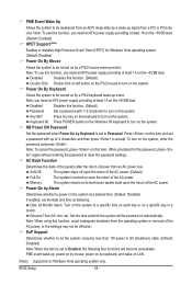
.... (Default: Disabled) If enabled, set the date and time as following: Date (of the AC power. Disabled Disables this item. Note: you need an ATX power supply providing at least 1A on upon the return of the AC power. (Default) Full-On The system is set a password with 1~5 characters to turn on the system... system at a specific time on each day or on a specific day in S5 (shutdown) state. (Default: Disabled) Note: When this function, you need an ATX power supply providing at least 1A on the system. EuP Support Determines whether to let the system consume less than 1W...
.... (Default: Disabled) If enabled, set the date and time as following: Date (of the AC power. Disabled Disables this item. Note: you need an ATX power supply providing at least 1A on upon the return of the AC power. (Default) Full-On The system is set a password with 1~5 characters to turn on the system... system at a specific time on each day or on a specific day in S5 (shutdown) state. (Default: Disabled) Note: When this function, you need an ATX power supply providing at least 1A on the system. EuP Support Determines whether to let the system consume less than 1W...

Manual
Page 77
... drives (to ensure optimal performance, it is set to AHCI or RAID mode. - 77 - Appendix Installing SATA hard drive(s) in your computer. Then connect the power connector from your computer Attach one hard drive. • An empty formatted floppy disk. • Windows Vista/XP setup disk. • Motherboard driver disk. 5-1-1 Configuring... for Windows XP. (Note 2) E. Chapter 5 Appendix 5-1 Configuring SATA Hard Drive(s) To configure SATA hard drive(s), follow the steps below: A. Install SATA hard drive(s) in your power supply to available SATA port on the motherboard.
... drives (to ensure optimal performance, it is set to AHCI or RAID mode. - 77 - Appendix Installing SATA hard drive(s) in your computer. Then connect the power connector from your computer Attach one hard drive. • An empty formatted floppy disk. • Windows Vista/XP setup disk. • Motherboard driver disk. 5-1-1 Configuring... for Windows XP. (Note 2) E. Chapter 5 Appendix 5-1 Configuring SATA Hard Drive(s) To configure SATA hard drive(s), follow the steps below: A. Install SATA hard drive(s) in your power supply to available SATA port on the motherboard.
Manual
Page 96
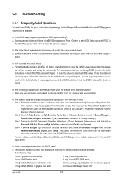
...mean? For motherboards that have turned my speaker to the maximum volume? If not, please update it from the battery holder to stop supplying power to the CMOS, which will clear the CMOS values after about one minute. If yes, please disable this device. (If not,... skip this step.) Step 3: Then go back to My Computer > Properties > Hardware > Device Manager > System devices and right-click on GIGABYTE's website. 5-3 Troubleshooting 5-3-1 Frequently Asked Questions To read more details, go to the instructions on after the computer shuts down ? A: For motherboards that 's...
...mean? For motherboards that have turned my speaker to the maximum volume? If not, please update it from the battery holder to stop supplying power to the CMOS, which will clear the CMOS values after about one minute. If yes, please disable this device. (If not,... skip this step.) Step 3: Then go back to My Computer > Properties > Hardware > Device Manager > System devices and right-click on GIGABYTE's website. 5-3 Troubleshooting 5-3-1 Frequently Asked Questions To read more details, go to the instructions on after the computer shuts down ? A: For motherboards that 's...

Manual
Page 98
No The power supply, CPU or CPU socket might fail. No The graphics card, expansion slot, or monitor might fail. The problem is working properly. Check if the keyboard ...
No The power supply, CPU or CPU socket might fail. No The graphics card, expansion slot, or monitor might fail. The problem is working properly. Check if the keyboard ...


