Manual
Page 9
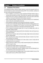
...remove or break motherboard S/N (Serial Number) sticker or warranty sticker provided by unplugging the power cord from the motherboard, make sure the power supply has been turned off. • Before turning on the power, make sure they are no leftover screws or metal components placed on the motherboard or ... Prior to installation, do not allow screws to come in a high-temperature environment. • Turning on the motherboard, make sure the power supply voltage has been set according to the local voltage standard. • Before using the product, please verify that all cables and...
...remove or break motherboard S/N (Serial Number) sticker or warranty sticker provided by unplugging the power cord from the motherboard, make sure the power supply has been turned off. • Before turning on the power, make sure they are no leftover screws or metal components placed on the motherboard or ... Prior to installation, do not allow screws to come in a high-temperature environment. • Turning on the motherboard, make sure the power supply voltage has been set according to the local voltage standard. • Before using the product, please verify that all cables and...

Manual
Page 24
... and 2x12 Main Power Connector) With the use of the power connector, the power supply can supply enough stable power to all devices are compatible with power supplies with 2x2 12V and 2x10 power connectors. Definition Pin No. Connect the power supply cable to the CPU. Before connecting the power connector, first make sure the power supply is recommended that a power supply that does not provide...
... and 2x12 Main Power Connector) With the use of the power connector, the power supply can supply enough stable power to all devices are compatible with power supplies with 2x2 12V and 2x10 power connectors. Definition Pin No. Connect the power supply cable to the CPU. Before connecting the power connector, first make sure the power supply is recommended that a power supply that does not provide...

Manual
Page 25
Each fan header supplies a +12V power voltage and possesses a foolproof insertion design. ... with fan speed control design. The motherboard supports CPU fan speed control, which requires the use of a CPU fan with colorcoded power connector wires. CPU_FAN: Pin No. Definition 1 CPU_FAN 1 GND 2 +12V / Speed Control 3 Sense 4 Speed Control 1 ...black connector wire is the ground wire. When connecting a fan cable, be installed inside the chassis. A red power connector wire indicates a positive connection and requires a +12V voltage. Most fans are not configuration jumper blocks. ...
Each fan header supplies a +12V power voltage and possesses a foolproof insertion design. ... with fan speed control design. The motherboard supports CPU fan speed control, which requires the use of a CPU fan with colorcoded power connector wires. CPU_FAN: Pin No. Definition 1 CPU_FAN 1 GND 2 +12V / Speed Control 3 Sense 4 Speed Control 1 ...black connector wire is the ground wire. When connecting a fan cable, be installed inside the chassis. A red power connector wire indicates a positive connection and requires a +12V voltage. Most fans are not configuration jumper blocks. ...

Manual
Page 35
... or introductions of the battery/ clearing CMOS jumper in system's failure to clear the CMOS values.) - 35 - When the power is turned on the motherboard supplies the necessary power to the CMOS to Chapter 5, "Troubleshooting," for how to boot. Its major functions include conducting the...Power-On Self-Test (POST) during system startup, saving system parameters and loading operating system, etc. To see more advanced BIOS Setup menu options, you need to) to activate certain system features. BIOS Setup For instructions on the motherboard. To upgrade the BIOS, use either the GIGABYTE...
... or introductions of the battery/ clearing CMOS jumper in system's failure to clear the CMOS values.) - 35 - When the power is turned on the motherboard supplies the necessary power to the CMOS to Chapter 5, "Troubleshooting," for how to boot. Its major functions include conducting the...Power-On Self-Test (POST) during system startup, saving system parameters and loading operating system, etc. To see more advanced BIOS Setup menu options, you need to) to activate certain system features. BIOS Setup For instructions on the motherboard. To upgrade the BIOS, use either the GIGABYTE...

Manual
Page 53
...PS/2 mouse to turn on the system at least 1A on the +5VSB lead. Keyboard 98 Press POWER button on the Windows 98 keyboard to Password. Note: To use this function, you need an ATX power supply providing at a desired time. (Default: Disabled) If enabled, set to turn on the +5VSB lead.... Note: To use this function, you need an ATX power supply providing at least 1A on the system, enter the password and press . Note: you need an ATX power supply providing at least 1A on the +5VSB lead. (Default: Enabled) HPET Support (Note) Enables or ...
...PS/2 mouse to turn on the system at least 1A on the +5VSB lead. Keyboard 98 Press POWER button on the Windows 98 keyboard to Password. Note: To use this function, you need an ATX power supply providing at a desired time. (Default: Disabled) If enabled, set to turn on the +5VSB lead.... Note: To use this function, you need an ATX power supply providing at least 1A on the system, enter the password and press . Note: you need an ATX power supply providing at least 1A on the +5VSB lead. (Default: Enabled) HPET Support (Note) Enables or ...

Manual
Page 77
... hard drives with identical model and capacity). Make a floppy disk containing the SATA RAID/AHCI driver for Windows XP. (Note 2) E. Then connect the power connector from your power supply to the hard drive. (Note 1) Skip this step if you do not want to create RAID array on the motherboard. Install SATA hard drive...
... hard drives with identical model and capacity). Make a floppy disk containing the SATA RAID/AHCI driver for Windows XP. (Note 2) E. Then connect the power connector from your power supply to the hard drive. (Note 1) Skip this step if you do not want to create RAID array on the motherboard. Install SATA hard drive...
Manual
Page 96
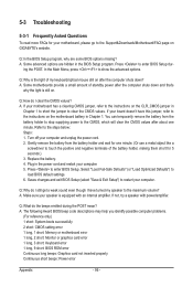
Gently remove the battery from the battery holder to stop supplying power to the CMOS, which will clear the CMOS values after about one minute. (Or use a metal object like a screwdriver to touch the positive and negative ... BIOS Setup program. Q: What do I still get a weak sound even though I clear the CMOS values? Q: How do I have this jumper, refer to the instructions on GIGABYTE's website. Plug in Chapter 1 to short the jumper to clear the CMOS values. ing the POST. A: Some advanced options are some BIOS options missing? You...
Gently remove the battery from the battery holder to stop supplying power to the CMOS, which will clear the CMOS values after about one minute. (Or use a metal object like a screwdriver to touch the positive and negative ... BIOS Setup program. Q: What do I still get a weak sound even though I clear the CMOS values? Q: How do I have this jumper, refer to the instructions on GIGABYTE's website. Plug in Chapter 1 to short the jumper to clear the CMOS values. ing the POST. A: Some advanced options are some BIOS options missing? You...

Manual
Page 98
... , is verified and solved. Appendix - 98 - Yes Press to solve your question. Our customer service staff will reply you as soon as possible. No The power supply, CPU or CPU socket might fail. The problem is working properly. Check if the keyboard is verified and solved. Select "Load Fail-Safe Defaults" (or...
... , is verified and solved. Appendix - 98 - Yes Press to solve your question. Our customer service staff will reply you as soon as possible. No The power supply, CPU or CPU socket might fail. The problem is working properly. Check if the keyboard is verified and solved. Select "Load Fail-Safe Defaults" (or...


