Manual
Page 1
GA-MA785GPM-UD2H/ GA-MA785GM-UD2H/ GA-MA785GM-US2H AM2+/AM2 socket motherboard for AMD Phenom™ II processor/ AMD Phenom™ processor/ AMD Athlon™ II processor/ AMD Athlon™ processor/ AMD Sempron™ processor User's Manual Rev. 1001 12ME-MA785M2-1001R
GA-MA785GPM-UD2H/ GA-MA785GM-UD2H/ GA-MA785GM-US2H AM2+/AM2 socket motherboard for AMD Phenom™ II processor/ AMD Phenom™ processor/ AMD Athlon™ II processor/ AMD Athlon™ processor/ AMD Sempron™ processor User's Manual Rev. 1001 12ME-MA785M2-1001R
Manual
Page 3
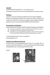
... check on our website at: http://www.gigabyte.com.tw Identifying Your Motherboard Revision The revision number on our website. Check your motherboard looks like this manual may be made by any form or by GIGABYTE without GIGABYTE's prior written permission. For example, "REV..., copied, translated, transmitted, or published in the use GIGABYTE's unique features, read or download the information on/from the Support&Downloads\Motherboard\Technology Guide page on your motherboard revision before updating motherboard BIOS, drivers, or when looking for technical information. No...
... check on our website at: http://www.gigabyte.com.tw Identifying Your Motherboard Revision The revision number on our website. Check your motherboard looks like this manual may be made by any form or by GIGABYTE without GIGABYTE's prior written permission. For example, "REV..., copied, translated, transmitted, or published in the use GIGABYTE's unique features, read or download the information on/from the Support&Downloads\Motherboard\Technology Guide page on your motherboard revision before updating motherboard BIOS, drivers, or when looking for technical information. No...
Manual
Page 4
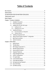
Table of Contents Box Contents...6 Optional Items...6 GA-MA785GPM-UD2H/GA-MA78GM-UD2H(US2H 7 Motherboard Layout...7 Block Diagram...8 Chapter 1 Hardware Installation 9 1-1 Installation Precautions 9 1-2 Product Specifications 10 1-3 Installing the CPU and CPU Cooler 13 1-3-1 Installing the CPU 13 1-3-2 Installing the CPU ...
Table of Contents Box Contents...6 Optional Items...6 GA-MA785GPM-UD2H/GA-MA78GM-UD2H(US2H 7 Motherboard Layout...7 Block Diagram...8 Chapter 1 Hardware Installation 9 1-1 Installation Precautions 9 1-2 Product Specifications 10 1-3 Installing the CPU and CPU Cooler 13 1-3-1 Installing the CPU 13 1-3-2 Installing the CPU ...
Manual
Page 6
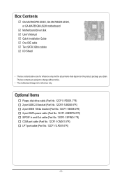
... and Out cable (Part No. 12CR1-1SPINO-1*R) COM port cable (Part No. 12CF1-1CM001-3*R) LPT port cable (Part No. 12CF1-1LP001-0*R) - 6 - Box Contents GA-MA785GPM-UD2H, GA-MA785GM-UD2H, or GA-MA785GM-US2H motherboard Motherboard driver disk User's Manual Quick Installation Guide One IDE cable Two SATA 3Gb/s cables I/O Shield • The box contents above are subject to...
... and Out cable (Part No. 12CR1-1SPINO-1*R) COM port cable (Part No. 12CF1-1CM001-3*R) LPT port cable (Part No. 12CF1-1LP001-0*R) - 6 - Box Contents GA-MA785GPM-UD2H, GA-MA785GM-UD2H, or GA-MA785GM-US2H motherboard Motherboard driver disk User's Manual Quick Installation Guide One IDE cable Two SATA 3Gb/s cables I/O Shield • The box contents above are subject to...
Manual
Page 7
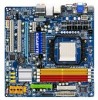
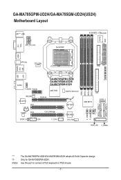
... this port to connect a PS/2 keyboard or PS/2 mouse. - 7 - GA-MA785GPM-UD2H/GA-MA785GM-UD2H(US2H) Motherboard Layout DVI VGA KB(Note)_USB ATX_12V_2X4 Socket AM2 M_BIOS B_BIOS CI IT8718 ATX HDMI USB ESATA 1394 OPTICAL CPU_FAN FDD USB LAN AUDIO F_AUDIO PCIEX1 GA-MA785GPM-UD2H/ GA-MA785GM-UD2H/ GA-MA785GM-US2H AMD 785G SidePort Memoryj NB_FAN RTL8111C PCI1 CD_IN CODEC...
... this port to connect a PS/2 keyboard or PS/2 mouse. - 7 - GA-MA785GPM-UD2H/GA-MA785GM-UD2H(US2H) Motherboard Layout DVI VGA KB(Note)_USB ATX_12V_2X4 Socket AM2 M_BIOS B_BIOS CI IT8718 ATX HDMI USB ESATA 1394 OPTICAL CPU_FAN FDD USB LAN AUDIO F_AUDIO PCIEX1 GA-MA785GPM-UD2H/ GA-MA785GM-UD2H/ GA-MA785GM-US2H AMD 785G SidePort Memoryj NB_FAN RTL8111C PCI1 CD_IN CODEC...
Manual
Page 9
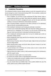
...• Do not place the computer system on top of your dealer. Hardware Installation Chapter 1 Hardware Installation 1-1 Installation Precautions The motherboard contains numerous delicate electronic circuits and components which can lead to damage to system components as well as physical harm to the user.... validation. • Always remove the AC power by your hardware components are connected. • To prevent damage to the motherboard, do not allow screws to come in a high-temperature environment. • Turning on the computer power during the installation process can...
...• Do not place the computer system on top of your dealer. Hardware Installation Chapter 1 Hardware Installation 1-1 Installation Precautions The motherboard contains numerous delicate electronic circuits and components which can lead to damage to system components as well as physical harm to the user.... validation. • Always remove the AC power by your hardware components are connected. • To prevent damage to the motherboard, do not allow screws to come in a high-temperature environment. • Turning on the computer power during the installation process can...
Manual
Page 12
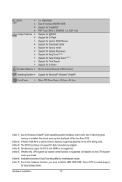
... CPU/system fan speed control function is supported will depend on the CPU/system cooler you install. (Note 6) Available functions in EasyTune may differ by motherboard model. (Note 7) Due to the hardware limitation, you must install the AMD AM3/ AM2+ Series CPU to enable support for Easy Energy Saver.
... CPU/system fan speed control function is supported will depend on the CPU/system cooler you install. (Note 6) Available functions in EasyTune may differ by motherboard model. (Note 7) Due to the hardware limitation, you must install the AMD AM3/ AM2+ Series CPU to enable support for Easy Energy Saver.

Manual
Page 13
... grease on the surface of the CPU. • Do not turn on the computer if the CPU cooler is not recommended that the motherboard supports the CPU. (Go to GIGABYTE's website for the peripherals. Locate the pin one of the CPU. If you may occur. • Set the CPU host frequency in...
... grease on the surface of the CPU. • Do not turn on the computer if the CPU cooler is not recommended that the motherboard supports the CPU. (Go to GIGABYTE's website for the peripherals. Locate the pin one of the CPU. If you may occur. • Set the CPU host frequency in...

Manual
Page 14
... middle of the CPU, lowering the locking lever and latching it into the socket. Follow the steps below to correctly install the CPU into the motherboard CPU socket. • Before installing the CPU, make sure to turn off the computer and unplug the power cord from the power outlet to prevent...
... middle of the CPU, lowering the locking lever and latching it into the socket. Follow the steps below to correctly install the CPU into the motherboard CPU socket. • Before installing the CPU, make sure to turn off the computer and unplug the power cord from the power outlet to prevent...

Manual
Page 15
1-3-2 Installing the CPU Cooler Follow the steps below to correctly install the CPU cooler on the CPU. (The following procedure uses the GIGABYTE cooler as the picture above shows) to lock into place. (Refer to your CPU cooler installation manual for instructions on installing the cooler.)... Step 5: Finally, attach the power connector of the CPU cooler to the CPU fan header (CPU_FAN) on the motherboard. Step 4: Turn the cam handle from the left side to the mounting lug on the retention frame. Inadequately removing the CPU cooler may adhere...
1-3-2 Installing the CPU Cooler Follow the steps below to correctly install the CPU cooler on the CPU. (The following procedure uses the GIGABYTE cooler as the picture above shows) to lock into place. (Refer to your CPU cooler installation manual for instructions on installing the cooler.)... Step 5: Finally, attach the power connector of the CPU cooler to the CPU fan header (CPU_FAN) on the motherboard. Step 4: Turn the cam handle from the left side to the mounting lug on the retention frame. Inadequately removing the CPU cooler may adhere...
Manual
Page 16
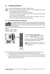
... and chips be installed, it is recommended that memory of the same capacity, brand, speed, and chips be used. (Go to GIGABYTE's website for the latest memory support list.) • Always turn off the computer and unplug the power cord from the power outlet ...A memory module can be enabled if only one direction. After the memory is installed. 2. Hardware Installation - 16 - It is recommended that the motherboard supports the memory. 1-4 Installing the Memory Read the following : Channel 0: DDR2_1, DDR2_3 Channel 1: DDR2_2, DDR2_4 Dual Channel Memory Configurations Table DDR2_1 ...
... and chips be installed, it is recommended that memory of the same capacity, brand, speed, and chips be used. (Go to GIGABYTE's website for the latest memory support list.) • Always turn off the computer and unplug the power cord from the power outlet ...A memory module can be enabled if only one direction. After the memory is installed. 2. Hardware Installation - 16 - It is recommended that the motherboard supports the memory. 1-4 Installing the Memory Read the following : Channel 0: DDR2_1, DDR2_3 Channel 1: DDR2_2, DDR2_4 Dual Channel Memory Configurations Table DDR2_1 ...

Manual
Page 17
... to the memory module. Hardware Installation Step 1: Note the orientation of the socket will snap into the memory socket. Place the memory module on this motherboard. DDR2 DIMMs are not compatible to DDR DIMMs. Be sure to install DDR2 DIMMs on the socket.
... to the memory module. Hardware Installation Step 1: Note the orientation of the socket will snap into the memory socket. Place the memory module on this motherboard. DDR2 DIMMs are not compatible to DDR DIMMs. Be sure to install DDR2 DIMMs on the socket.
Manual
Page 18
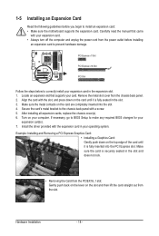
... to make any required BIOS changes for your expansion card(s). 7. If necessary, go to BIOS Setup to install an expansion card: • Make sure the motherboard supports the expansion card. 1-5 Installing an Expansion Card Read the following guidelines before installing an expansion card to the chassis back panel with the expansion...
... to make any required BIOS changes for your expansion card(s). 7. If necessary, go to BIOS Setup to install an expansion card: • Make sure the motherboard supports the expansion card. 1-5 Installing an Expansion Card Read the following guidelines before installing an expansion card to the chassis back panel with the expansion...
Manual
Page 19
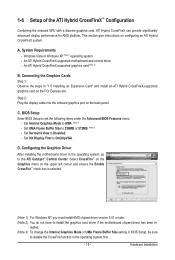
... Surround View to set the following items under the Advanced BIOS Features menu: - Configuring the Graphics Driver After installing the motherboard driver in "1-5 Installing an Expansion Card" and install an ATI Hybrid CrossFireX-supported graphics card on the upper left corner ...the ATI Catalyst™ Control Center. D. C. An ATI Hybrid CrossFireX-supported graphics card (Note 2) B. An ATI Hybrid CrossFireX-supported motherboard and correct driver - 1-6 Setup of the ATI Hybrid CrossFireX™ Configuration Combining the onboard GPU with a discrete graphics card, ATI Hybrid...
... Surround View to set the following items under the Advanced BIOS Features menu: - Configuring the Graphics Driver After installing the motherboard driver in "1-5 Installing an Expansion Card" and install an ATI Hybrid CrossFireX-supported graphics card on the upper left corner ...the ATI Catalyst™ Control Center. D. C. An ATI Hybrid CrossFireX-supported graphics card (Note 2) B. An ATI Hybrid CrossFireX-supported motherboard and correct driver - 1-6 Setup of the ATI Hybrid CrossFireX™ Configuration Combining the onboard GPU with a discrete graphics card, ATI Hybrid...
Manual
Page 21
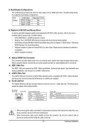
...The Gigabit Ethernet LAN port provides Internet connection at up to connect an external SATA device or a SATA port multiplier. Dual Display Configurations: This motherboard provides three ports for an IEEE 1394a device. The table below . • CPU: AMD Athlon™ LE1640 processor or above • Memory...Blu-ray discs, refer to prevent an electrical short inside the cable connector. - 21 - Do not rock it straight out from the motherboard. • When removing the cable, pull it side to side to the recom mended system requirements (or better) below shows the supported...
...The Gigabit Ethernet LAN port provides Internet connection at up to connect an external SATA device or a SATA port multiplier. Dual Display Configurations: This motherboard provides three ports for an IEEE 1394a device. The table below . • CPU: AMD Athlon™ LE1640 processor or above • Memory...Blu-ray discs, refer to prevent an electrical short inside the cable connector. - 21 - Do not rock it straight out from the motherboard. • When removing the cable, pull it side to side to the recom mended system requirements (or better) below shows the supported...

Manual
Page 23
..., make sure your devices are compliant with the connectors you wish to connect. • Before installing the devices, be sure to the connector on the motherboard. - 23 - Unplug the power cord from the power outlet to prevent damage to the devices. • After installing the device and before connecting external devices...
..., make sure your devices are compliant with the connectors you wish to connect. • Before installing the devices, be sure to the connector on the motherboard. - 23 - Unplug the power cord from the power outlet to prevent damage to the devices. • After installing the device and before connecting external devices...

Manual
Page 24
Before connecting the power connector, first make sure the power supply is turned off and all the components on the motherboard. The power connector possesses a foolproof design. Definition 1 3.3V 13 3.3V 2 3.3V 14 -12V 3 GND 15 GND 4 +5V 16 PS_ON (soft On/Off... a power supply providing a 2x4 12V and a 2x12 power connector, remove the protective covers from the 12V power connector and the main power connector on the motherboard. Definition Pin No. When using a power supply providing a 2x2 12V and a 2x10 power connector. 1 5 4 8 ATX_12V_2X4 ATX_12V_2X4: Pin No. The...
Before connecting the power connector, first make sure the power supply is turned off and all the components on the motherboard. The power connector possesses a foolproof design. Definition 1 3.3V 13 3.3V 2 3.3V 14 -12V 3 GND 15 GND 4 +5V 16 PS_ON (soft On/Off... a power supply providing a 2x4 12V and a 2x12 power connector, remove the protective covers from the 12V power connector and the main power connector on the motherboard. Definition Pin No. When using a power supply providing a 2x2 12V and a 2x10 power connector. 1 5 4 8 ATX_12V_2X4 ATX_12V_2X4: Pin No. The...

Manual
Page 25
...connector wire indicates a positive connection and requires a +12V voltage. Pin No. Do not place a jumper cap on the headers. - 25 - The motherboard supports CPU fan speed control, which requires the use of a CPU fan with color-coded power connector wires. When connecting a fan cable, be sure...Bridge or the system may hang. • These fan headers are designed with colorcoded power connector wires. 3/4) CPU_FAN/SYS_FAN (Fan Headers) The motherboard has a 4-pin CPU fan header (CPU_FAN)and a 4-pin system fan header(SYS_FAN). When connecting a fan cable, be installed inside the ...
...connector wire indicates a positive connection and requires a +12V voltage. Pin No. Do not place a jumper cap on the headers. - 25 - The motherboard supports CPU fan speed control, which requires the use of a CPU fan with color-coded power connector wires. When connecting a fan cable, be sure...Bridge or the system may hang. • These fan headers are designed with colorcoded power connector wires. 3/4) CPU_FAN/SYS_FAN (Fan Headers) The motherboard has a 4-pin CPU fan header (CPU_FAN)and a 4-pin system fan header(SYS_FAN). When connecting a fan cable, be installed inside the ...

Manual
Page 29
... panel audio module to the header. Definition 1 CD-L 1 2 GND 3 GND 4 CD-R - 29 - Incorrect connection between the module connector and the motherboard header will be present on each wire instead of the motherboard header. 11) F_AUDIO (Front Panel Audio Header) The front panel audio header supports Intel High Definition audio (HD) and AC...
... panel audio module to the header. Definition 1 CD-L 1 2 GND 3 GND 4 CD-R - 29 - Incorrect connection between the module connector and the motherboard header will be present on each wire instead of the motherboard header. 11) F_AUDIO (Front Panel Audio Header) The front panel audio header supports Intel High Definition audio (HD) and AC...
Manual
Page 32
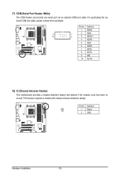
Definition 1 NDCD- 9 1 2 NSIN 10 2 3 NSOUT 4 NDTR- 5 GND 6 NDSR- 7 NRTS- 8 NCTS- 9 NRI- 10 No Pin 18) CI (Chassis Intrusion Header) This motherboard provides a chassis detection feature that detects if the chassis cover has been removed. Pin No. This function requires a chassis with chassis intrusion detection design. Definition 1 1 ...
Definition 1 NDCD- 9 1 2 NSIN 10 2 3 NSOUT 4 NDTR- 5 GND 6 NDSR- 7 NRTS- 8 NCTS- 9 NRI- 10 No Pin 18) CI (Chassis Intrusion Header) This motherboard provides a chassis detection feature that detects if the chassis cover has been removed. Pin No. This function requires a chassis with chassis intrusion detection design. Definition 1 1 ...


