
Manual
Page 23
... cable. Do not place a jumper cap on the headers. 6) FDD (Floppy Disk Drive Connector) This connector is recommended that a system fan be installed inside the chassis. 1 CPU_FAN CPU_FAN: Pin No. 1 2 3 4 Definition GND +12V / Speed Control Sense Speed Control 1 SYS_FAN1 SYS_FAN1: Pin No. 1 2 3 4 ...different color. 33 1 34 2 - 23 - The motherboard supports CPU fan speed control, which requires the use of the cable is the ground wire). Overheating may result in the correct orientation (the black connector wire is typically designated by a stripe of floppy disk drives...
... cable. Do not place a jumper cap on the headers. 6) FDD (Floppy Disk Drive Connector) This connector is recommended that a system fan be installed inside the chassis. 1 CPU_FAN CPU_FAN: Pin No. 1 2 3 4 Definition GND +12V / Speed Control Sense Speed Control 1 SYS_FAN1 SYS_FAN1: Pin No. 1 2 3 4 ...different color. 33 1 34 2 - 23 - The motherboard supports CPU fan speed control, which requires the use of the cable is the ground wire). Overheating may result in the correct orientation (the black connector wire is typically designated by a stripe of floppy disk drives...
Manual
Page 26
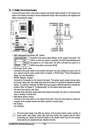
...LED, speaker and etc. PW+ PWSPEAK+ SPEAK- 2 20 1 19 HD+ HD- GA-MA770T-UD3/US3 Motherboard - 26 - If a problem is operating. Refer to Chapter 5, "Troubleshooting," for more information). • SPEAK (Speaker, Orange): Connects to the speaker on the chassis front panel. 11) F_PANEL (Front Panel Header) Connect the power switch, reset switch, ...system is detected, the BIOS may issue beeps in different patterns to indicate the problem. The S0 On LED is on the chassis front panel to this header, make sure the wire assignments and the pin assignments are matched correctly.
...LED, speaker and etc. PW+ PWSPEAK+ SPEAK- 2 20 1 19 HD+ HD- GA-MA770T-UD3/US3 Motherboard - 26 - If a problem is operating. Refer to Chapter 5, "Troubleshooting," for more information). • SPEAK (Speaker, Orange): Connects to the speaker on the chassis front panel. 11) F_PANEL (Front Panel Header) Connect the power switch, reset switch, ...system is detected, the BIOS may issue beeps in different patterns to indicate the problem. The S0 On LED is on the chassis front panel to this header, make sure the wire assignments and the pin assignments are matched correctly.

Manual
Page 27
...header supports HD audio by default. For information about connecting the front panel audio module that has different wire assignments, please contact the chassis manufacturer. 13) CD_IN (CD In Connector) You may connect your chassis front panel audio module to activate AC'97 functionality via the audio software in Chapter 5, "Configuring 2/4/5.1/7.1-Channel... audio module), refer to work or even damage it. Definition 1 CD-L 2 GND 1 3 GND 4 CD-R - 27 - Incorrect connection between the module connector and the motherboard header will be present on each wire instead of the...
...header supports HD audio by default. For information about connecting the front panel audio module that has different wire assignments, please contact the chassis manufacturer. 13) CD_IN (CD In Connector) You may connect your chassis front panel audio module to activate AC'97 functionality via the audio software in Chapter 5, "Configuring 2/4/5.1/7.1-Channel... audio module), refer to work or even damage it. Definition 1 CD-L 2 GND 1 3 GND 4 CD-R - 27 - Incorrect connection between the module connector and the motherboard header will be present on each wire instead of the...


