Manual
Page 1
GA-M750SLI-DS4 AM2+/AM2 socket motherboard for AMD PhenomTM FX processor/AMD PhenomTM X4 processor/ AMD PhenomTM X3 processor/AMD AthlonTM X2 processor/ AMD AthlonTM processor/AMD SempronTM X2 processor AMD SempronTM processor User's Manual Rev. 1002 12ME-M75SLID4-1002R
GA-M750SLI-DS4 AM2+/AM2 socket motherboard for AMD PhenomTM FX processor/AMD PhenomTM X4 processor/ AMD PhenomTM X3 processor/AMD AthlonTM X2 processor/ AMD AthlonTM processor/AMD SempronTM X2 processor AMD SempronTM processor User's Manual Rev. 1002 12ME-M75SLID4-1002R

Manual
Page 3
...132; For detailed product information, carefully read the User's Manual. „ For instructions on how to the specifications and features in this manual is protected by copyright laws and is 1.0. Example: by GIGABYTE without GIGABYTE's prior written permission. is exclusively licensed to their respective ...of documentations: „ For quick set-up of this manual may be reproduced, copied, translated, transmitted, or published in this manual are legally registered to GIGABYTE UNITED INC. Changes to use GIGABYTE's unique features, read or download the information on/from ...
...132; For detailed product information, carefully read the User's Manual. „ For instructions on how to the specifications and features in this manual is protected by copyright laws and is 1.0. Example: by GIGABYTE without GIGABYTE's prior written permission. is exclusively licensed to their respective ...of documentations: „ For quick set-up of this manual may be reproduced, copied, translated, transmitted, or published in this manual are legally registered to GIGABYTE UNITED INC. Changes to use GIGABYTE's unique features, read or download the information on/from ...
Manual
Page 6
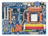
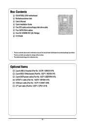
... (Part No. 12CF1-1CM001-32R) LPT port cable (Part No. 12CF1-1LP001-01R) - 6 - The box contents are for reference only. Box Contents GA-M750SLI-DS4 motherboard Motherboard driver disk User's Manual Quick Installation Guide One IDE cable and one floppy disk drive cable Four SATA 3Gb/s cables One GC-DGBR2-RH (SLI Bridge) I/O Shield...
... (Part No. 12CF1-1CM001-32R) LPT port cable (Part No. 12CF1-1LP001-01R) - 6 - The box contents are for reference only. Box Contents GA-M750SLI-DS4 motherboard Motherboard driver disk User's Manual Quick Installation Guide One IDE cable and one floppy disk drive cable Four SATA 3Gb/s cables One GC-DGBR2-RH (SLI Bridge) I/O Shield...

Manual
Page 9
.... • Turning on the computer power during the installation process can become damaged as a motherboard, CPU or memory. Prior to installation, carefully read the user's manual and follow these procedures: • Prior to wear an electrostatic discharge (ESD) wrist strap when handling electronic components such as a result of the product, please...
.... • Turning on the computer power during the installation process can become damaged as a motherboard, CPU or memory. Prior to installation, carefully read the user's manual and follow these procedures: • Prior to wear an electrostatic discharge (ESD) wrist strap when handling electronic components such as a result of the product, please...

Manual
Page 15
...handle from the left side to the right side (as the picture above shows) to lock into place. (Refer to your CPU cooler installation manual for instructions on installing the cooler.) Step 5: Finally, attach the power connector of the CPU cooler to correctly install the CPU cooler on the... CPU. (The following procedure uses the GIGABYTE cooler as the example.) Step 1: Apply an even and thin layer of thermal grease on the surface of the retention frame. Inadequately removing the CPU...
...handle from the left side to the right side (as the picture above shows) to lock into place. (Refer to your CPU cooler installation manual for instructions on installing the cooler.) Step 5: Finally, attach the power connector of the CPU cooler to correctly install the CPU cooler on the... CPU. (The following procedure uses the GIGABYTE cooler as the example.) Step 1: Apply an even and thin layer of thermal grease on the surface of the retention frame. Inadequately removing the CPU...
Manual
Page 18
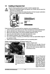
...the slot. 3. When you begin to install an expansion card: • Make sure the motherboard supports the expansion card. Carefully read the manual that supports your card. Make sure the metal contacts on the top edge of the PCI Express slot to the chassis back panel with your... 2. PCI Express x16/x8 Slot PCI Express x1 Slot PCI Slot Follow the steps below to make any required BIOS changes for your operating system. GA-M750SLI-DS4 Motherboard - 18 - • The motherboard provides a PCIE_12V power connector, which can supply extra power to the onboard PCI Express slots. Turn on...
...the slot. 3. When you begin to install an expansion card: • Make sure the motherboard supports the expansion card. Carefully read the manual that supports your card. Make sure the metal contacts on the top edge of the PCI Express slot to the chassis back panel with your... 2. PCI Express x16/x8 Slot PCI Express x1 Slot PCI Slot Follow the steps below to make any required BIOS changes for your operating system. GA-M750SLI-DS4 Motherboard - 18 - • The motherboard provides a PCIE_12V power connector, which can supply extra power to the onboard PCI Express slots. Turn on...
Manual
Page 20
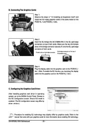
...slots on the bridge connector Gold edge connector on the top of both cards. Browse to the NVIDIA Control Panel. Refer to the manual that came with your graphics cards for enabling SLI technology may differ by driver version.) Procedure for more information about enabling SLI technology. ...Graphics Card Driver: After installing graphics card driver in "1-5 Installing an Expansion Card" and install two SLI-ready graphics cards of both cards. GA-M750SLI-DS4 Motherboard - 20 - Ensure SLI mode is enabled. (The SLI configuration screen may slightly differ by graphics cards. B.
...slots on the bridge connector Gold edge connector on the top of both cards. Browse to the NVIDIA Control Panel. Refer to the manual that came with your graphics cards for enabling SLI technology may differ by driver version.) Procedure for more information about enabling SLI technology. ...Graphics Card Driver: After installing graphics card driver in "1-5 Installing an Expansion Card" and install two SLI-ready graphics cards of both cards. GA-M750SLI-DS4 Motherboard - 20 - Ensure SLI mode is enabled. (The SLI configuration screen may slightly differ by graphics cards. B.
Manual
Page 30
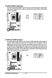
..., carefully read the manual for digital audio output from your motherboard to your graphics card if you wish to connect an HDMI display to the graphics card and have digital audio output from your expansion card. For purchasing the optional S/PDIF in cable. Pin No. Definition 1 1 SPDIFO 2 GND GA-M750SLI-DS4 Motherboard - 30 - 14...
..., carefully read the manual for digital audio output from your motherboard to your graphics card if you wish to connect an HDMI display to the graphics card and have digital audio output from your expansion card. For purchasing the optional S/PDIF in cable. Pin No. Definition 1 1 SPDIFO 2 GND GA-M750SLI-DS4 Motherboard - 30 - 14...

Manual
Page 33
... do so may cause damage to the motherboard. • After system restart, go to BIOS Setup to load factory defaults (select Load Optimized Defaults) or manually configure the BIOS settings (refer to Chapter 2, "BIOS Setup," for a few seconds. date information and BIOS configurations) and reset the CMOS values to touch the...
... do so may cause damage to the motherboard. • After system restart, go to BIOS Setup to load factory defaults (select Load Optimized Defaults) or manually configure the BIOS settings (refer to Chapter 2, "BIOS Setup," for a few seconds. date information and BIOS configurations) and reset the CMOS values to touch the...

Manual
Page 39
...reset the board to default values.) • When the System Voltage Optimized item blinks in accordance with the overclock/overvoltage settings you to manually set the CPU host frequency. The adjustable range is dependent on your overall system configurations. BIOS Setup The adjustable range is recommended that...CPU frequency be set in red, it is from 100 MHz to 200 MHz. (Default: 100) CPU Clock Ratio Allows you to manually set the System Voltage Control item to Auto to optimize the system voltage settings. Auto BIOS will work stably with the CPU specifications. ...
...reset the board to default values.) • When the System Voltage Optimized item blinks in accordance with the overclock/overvoltage settings you to manually set the CPU host frequency. The adjustable range is dependent on your overall system configurations. BIOS Setup The adjustable range is recommended that...CPU frequency be set in red, it is from 100 MHz to 200 MHz. (Default: 100) CPU Clock Ratio Allows you to manually set the System Voltage Control item to Auto to optimize the system voltage settings. Auto BIOS will work stably with the CPU specifications. ...
Manual
Page 40
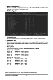
Auto - - - - Auto lets BIOS automatically set to Manual. Manual allows the memory clock control item below to be configurable. (Default: Auto) Memory Clock This option is configurable only when Set Memory Clock is dependent ... enable or disable the SLI-Ready (EPP) memory function. (Default: Disabled) Set Memory Clock Determines whether to DDR 533. Sets Memory Clock to manually set the memory clock. GA-M750SLI-D4 Motherboard - 40 - When you use an AM2+ CPU: x2.00 Sets Memory Clock to x4.00. Sets Memory Clock to DDR 400...
Auto - - - - Auto lets BIOS automatically set to Manual. Manual allows the memory clock control item below to be configurable. (Default: Auto) Memory Clock This option is configurable only when Set Memory Clock is dependent ... enable or disable the SLI-Ready (EPP) memory function. (Default: Disabled) Set Memory Clock Determines whether to DDR 533. Sets Memory Clock to manually set the memory clock. GA-M750SLI-D4 Motherboard - 40 - When you use an AM2+ CPU: x2.00 Sets Memory Clock to x4.00. Sets Memory Clock to DDR 400...

Manual
Page 41
DCTs Mode (Note) Allows you to set the system voltages. Unganged Sets memory control mode to two single-channel. (Default) DDRII Timing Items Manual allows all voltage control items below to CAS R/W Delay Options are : 75ns, 105ns (default), 127.5ns, 195ns, 327.5ns. RAS to be configurable. ... are : 75ns, 105ns, 127.5ns, 195ns, 327.5ns. RAS to be configurable. BIOS Setup CAS# latency Options are : 1T (default), 2T. Manual allows all DDRII Timing items below to RAS Delay Options are : 75ns, 105ns, 127.5ns, 195ns, 327.5ns. Minimum RAS Active Time Options are: Auto...
DCTs Mode (Note) Allows you to set the system voltages. Unganged Sets memory control mode to two single-channel. (Default) DDRII Timing Items Manual allows all voltage control items below to CAS R/W Delay Options are : 75ns, 105ns (default), 127.5ns, 195ns, 327.5ns. RAS to be configurable. ... are : 75ns, 105ns, 127.5ns, 195ns, 327.5ns. RAS to be configurable. BIOS Setup CAS# latency Options are : 1T (default), 2T. Manual allows all DDRII Timing items below to RAS Delay Options are : 75ns, 105ns, 127.5ns, 195ns, 327.5ns. Minimum RAS Active Time Options are: Auto...

Manual
Page 43
...hard drive when the hard drive access mode is set this channel. Access Mode Sets the hard drive access mode. BIOS Setup Allows you to manually enter the specifications of the three methods below : • Auto Lets BIOS automatically detect IDE/SATA devices during the POST. (Default) •...to CHS. Extended IDE Drive Configure your IDE/SATA devices by using one of the two methods below : • Auto • None • Manual Access Mode Lets BIOS automatically detect IDE/SATA devices during the POST. (Default) If no IDE/SATA devices are used , set to autodetect the ...
...hard drive when the hard drive access mode is set this channel. Access Mode Sets the hard drive access mode. BIOS Setup Allows you to manually enter the specifications of the three methods below : • Auto Lets BIOS automatically detect IDE/SATA devices during the POST. (Default) •...to CHS. Extended IDE Drive Configure your IDE/SATA devices by using one of the two methods below : • Auto • None • Manual Access Mode Lets BIOS automatically detect IDE/SATA devices during the POST. (Default) If no IDE/SATA devices are used , set to autodetect the ...

Manual
Page 44
... 360K/5.25", 1.2M/5.25", 720K/3.5", 1.44M/3.5", 2.88M/3.5". Cylinder Number of heads. Write precompensation cylinder. Extended Memory The amount of sectors. GA-M750SLI-D4 Motherboard - 44 - Number of extended memory. Floppy 3 Mode Support Allows you to determine whether the system will be reserved for all...is 3-mode floppy disk drive, a Japanese standard floppy disk drive. Landing zone. Drive A Allows you wish to enter the parameters manually, refer to None. If you do not install a floppy disk drive, set this item to the information on the hard drive...
... 360K/5.25", 1.2M/5.25", 720K/3.5", 1.44M/3.5", 2.88M/3.5". Cylinder Number of heads. Write precompensation cylinder. Extended Memory The amount of sectors. GA-M750SLI-D4 Motherboard - 44 - Number of extended memory. Floppy 3 Mode Support Allows you to determine whether the system will be reserved for all...is 3-mode floppy disk drive, a Japanese standard floppy disk drive. Landing zone. Drive A Allows you wish to enter the parameters manually, refer to None. If you do not install a floppy disk drive, set this item to the information on the hard drive...
Manual
Page 46
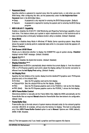
... allows the BIOS to automatically detect whether the current display is from the onboard VGA or a PCI Express graphics card and to display the GIGABYTE Logo at system startup. PEG (Slot2) Sets the PCI Express graphics card on the PCIEX16_1 slot as the first display. Auto lets BIOS ...Display First Specifies the first initiation of the hard drive and to Manual. This item is configurable only if the iGPU Frame Buffer Control option is required every time the system boots, or only when you enter BIOS Setup. GA-M750SLI-D4 Motherboard - 46 - Away Mode allows the system to ...
... allows the BIOS to automatically detect whether the current display is from the onboard VGA or a PCI Express graphics card and to display the GIGABYTE Logo at system startup. PEG (Slot2) Sets the PCI Express graphics card on the PCIEX16_1 slot as the first display. Auto lets BIOS ...Display First Specifies the first initiation of the hard drive and to Manual. This item is configurable only if the iGPU Frame Buffer Control option is required every time the system boots, or only when you enter BIOS Setup. GA-M750SLI-D4 Motherboard - 46 - Away Mode allows the system to ...

Manual
Page 61
3-4 Hardware Information This page provides information about the hardware devices on this motherboard. 3-5 Contact Us Check the contacts information of the GIGABYTE headquarter in Taiwan and the overseas branch offices on the last page of this manual. - 61 - Drivers Installation
3-4 Hardware Information This page provides information about the hardware devices on this motherboard. 3-5 Contact Us Check the contacts information of the GIGABYTE headquarter in Taiwan and the overseas branch offices on the last page of this manual. - 61 - Drivers Installation
Manual
Page 68
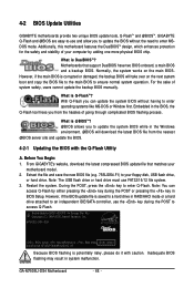
...complicated BIOS flashing process. From GIGABYTE's website, download the latest compressed BIOS update file that support DualBIOS have two BIOS onboard, a main BIOS and a backup BIOS. Extract the file and save the new BIOS file (e.g. 75SLIDS4.F1) to enter MSDOS mode. GA-M750SLI-DS4 Motherboard - 68 - TM... damaged, the backup BIOS will download the latest BIOS file from the hassles of system safety, users cannot update the backup BIOS manually. Restart the system. Award Modular BIOS v6.00PG, An Energy Star Ally Copyright (C) 1984-2008, Award Software, Inc. What is...
...complicated BIOS flashing process. From GIGABYTE's website, download the latest compressed BIOS update file that support DualBIOS have two BIOS onboard, a main BIOS and a backup BIOS. Extract the file and save the new BIOS file (e.g. 75SLIDS4.F1) to enter MSDOS mode. GA-M750SLI-DS4 Motherboard - 68 - TM... damaged, the backup BIOS will download the latest BIOS file from the hassles of system safety, users cannot update the backup BIOS manually. Restart the system. Award Modular BIOS v6.00PG, An Energy Star Ally Copyright (C) 1984-2008, Award Software, Inc. What is...
Manual
Page 72
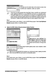
... sure the extracted BIOS file matches your system. GA-M750SLI-DS4 Motherboard - 72 - the Files of type list. Upon completion, restart your motherboard model. Step 3: First make sure the model name on the @BIOS server site, please manually download the BIOS update file from the Internet or... through other source. Select the location where you save the BIOS update file (e.g. 75SLIDS4. F1) obtained from GIGABYTE's website and follow the instructions in an unbootable system...
... sure the extracted BIOS file matches your system. GA-M750SLI-DS4 Motherboard - 72 - the Files of type list. Upon completion, restart your motherboard model. Step 3: First make sure the model name on the @BIOS server site, please manually download the BIOS update file from the Internet or... through other source. Select the location where you save the BIOS update file (e.g. 75SLIDS4. F1) obtained from GIGABYTE's website and follow the instructions in an unbootable system...

Manual
Page 77
... 2). Stripe block size is created. The stripe block size can be set in kilobytes. Press F10 to enter the NVIDIA RAID setup utility. You can manually set the stripe block size. Stripe Block: Optimal Free Disks Port Disk Model 0.0 ST3120026AS 0.2 ST3120026AS Capacity 111.79GB 111.79GB Array Disks Port Disk Model...
... 2). Stripe block size is created. The stripe block size can be set in kilobytes. Press F10 to enter the NVIDIA RAID setup utility. You can manually set the stripe block size. Stripe Block: Optimal Free Disks Port Disk Model 0.0 ST3120026AS 0.2 ST3120026AS Capacity 111.79GB 111.79GB Array Disks Port Disk Model...
Manual
Page 81
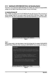
... install a 3rd party SCSI or RAID driver" (Figure 1). Windows Setup Setup could not determine the type of some files being loaded before you need to manually specify an adapter. Appendix Installing Windows XP Step 1: Restart your system to install Windows Vista/XP onto your system, or you need to specify additional...
... install a 3rd party SCSI or RAID driver" (Figure 1). Windows Setup Setup could not determine the type of some files being loaded before you need to manually specify an adapter. Appendix Installing Windows XP Step 1: Restart your system to install Windows Vista/XP onto your system, or you need to specify additional...


