
Manual
Page 1
GA-M68SM-S2L AM2 socket motherboard for AMD AthlonTM 64 FX processor/ AMD AthlonTM 64 X2 Dual-Core processor/ AMD AthlonTM 64 processor/AMD SempronTM processor User's Manual Rev. 1003 12ME-M68SMS2L-1003R
GA-M68SM-S2L AM2 socket motherboard for AMD AthlonTM 64 FX processor/ AMD AthlonTM 64 X2 Dual-Core processor/ AMD AthlonTM 64 processor/AMD SempronTM processor User's Manual Rev. 1003 12ME-M68SMS2L-1003R

Manual
Page 2
Motherboard GA-M68SM-S2L Oct. 2, 2007 Motherboard GA-M68SM-S2L Oct. 2, 2007
Motherboard GA-M68SM-S2L Oct. 2, 2007 Motherboard GA-M68SM-S2L Oct. 2, 2007
Manual
Page 3
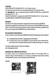
... licensed to the specifications and features in any means without prior notice. For product-related information, check on our website at: http://www.gigabyte.com.tw Identifying Your Motherboard Revision The revision number on our website. Copyright © 2008 GIGA-BYTE TECHNOLOGY CO., LTD. The trademarks mentioned in this manual may be...
... licensed to the specifications and features in any means without prior notice. For product-related information, check on our website at: http://www.gigabyte.com.tw Identifying Your Motherboard Revision The revision number on our website. Copyright © 2008 GIGA-BYTE TECHNOLOGY CO., LTD. The trademarks mentioned in this manual may be...

Manual
Page 4
Table of Contents Box Contents ...6 OptionalItems ...6 GA-M68SM-S2L Motherboard Layout 7 Block Diagram ...8 Chapter 1 Hardware Installation 9 1-1 Installation Precautions 9 1-2 Product Specifications 10 1-3 Installing the CPU and CPU Cooler 12 1-3-1 Installing the CPU 12 1-3-2 Installing the CPU ...
Table of Contents Box Contents ...6 OptionalItems ...6 GA-M68SM-S2L Motherboard Layout 7 Block Diagram ...8 Chapter 1 Hardware Installation 9 1-1 Installation Precautions 9 1-2 Product Specifications 10 1-3 Installing the CPU and CPU Cooler 12 1-3-1 Installing the CPU 12 1-3-2 Installing the CPU ...

Manual
Page 6
The box contents are for reference only and the actual items shall depend on product package you obtain. Optional Items 2-port USB 2.0 bracket (Part No. 12CR1-1UB030-51R) 2-port SATA power cable (Part No. 12CF1-2SERPW-01R) COM port cable (Part No. 12CF1-1CM001-32R) S/PDIF out cable (Part No. 12CR1-1SPOUT-02R) - 6 - Box Contents GA-M68SM-S2L motherboard Motherboard driver disk User's Manual Quick Installation Guide One IDE cable Two SATA 3Gb/s cables I/O Shield The box contents above are subject to change without notice.
The box contents are for reference only and the actual items shall depend on product package you obtain. Optional Items 2-port USB 2.0 bracket (Part No. 12CR1-1UB030-51R) 2-port SATA power cable (Part No. 12CF1-2SERPW-01R) COM port cable (Part No. 12CF1-1CM001-32R) S/PDIF out cable (Part No. 12CR1-1SPOUT-02R) - 6 - Box Contents GA-M68SM-S2L motherboard Motherboard driver disk User's Manual Quick Installation Guide One IDE cable Two SATA 3Gb/s cables I/O Shield The box contents above are subject to change without notice.

Manual
Page 9
...Always remove the AC power by your hands dry and first touch a metal object to eliminate static electricity. • Prior to installing the motherboard, please have a problem related to the use of the product, please consult a certified computer technician. - 9 - If you are uncertain ... an electrostatic shielding container. • Before unplugging the power supply cable from the power outlet before installing or removing the motherboard or other hardware components. • When connecting hardware components to the internal connectors on the computer power during the installation ...
...Always remove the AC power by your hands dry and first touch a metal object to eliminate static electricity. • Prior to installing the motherboard, please have a problem related to the use of the product, please consult a certified computer technician. - 9 - If you are uncertain ... an electrostatic shielding container. • Before unplugging the power supply cable from the power outlet before installing or removing the motherboard or other hardware components. • When connecting hardware components to the internal connectors on the computer power during the installation ...

Manual
Page 10
... processor/AMD AthlonTM 64 X2 Dual-Core processor/ AMD AthlonTM 64 processor/AMD SempronTM processor (Go to GIGABYTE's website for the latest CPU support list.) 2000 MT/s nVIDIA® GeForce 7025/nForce 630a chipset ... memory (Note 1) Dual channel memory architecture Support for DDR2 800/667/533 MHz memory modules (Go to GIGABYTE's website for the latest memory support list.) Realtek AL662 codec High Definition Audio 2/4/5.1-channel Support for S/PDIF ... Out header 3 x USB 2.0/1.1 headers 1 x serial port header 1 x chassis intrusion header 1 x power LED header GA-M68SM-S2L Motherboard - 10 -
... processor/AMD AthlonTM 64 X2 Dual-Core processor/ AMD AthlonTM 64 processor/AMD SempronTM processor (Go to GIGABYTE's website for the latest CPU support list.) 2000 MT/s nVIDIA® GeForce 7025/nForce 630a chipset ... memory (Note 1) Dual channel memory architecture Support for DDR2 800/667/533 MHz memory modules (Go to GIGABYTE's website for the latest memory support list.) Realtek AL662 codec High Definition Audio 2/4/5.1-channel Support for S/PDIF ... Out header 3 x USB 2.0/1.1 headers 1 x serial port header 1 x chassis intrusion header 1 x power LED header GA-M68SM-S2L Motherboard - 10 -

Manual
Page 11
.... (Note 2) Whether the CPU fan speed control function is supported will depend on the CPU you install. (Note 3) Available functions in EasyTune may differ by motherboard model. - 11 -
.... (Note 2) Whether the CPU fan speed control function is supported will depend on the CPU you install. (Note 3) Available functions in EasyTune may differ by motherboard model. - 11 -

Manual
Page 12
.... • Apply an even and thin layer of thermal grease on the surface of the CPU socket and the CPU. mended that the motherboard supports the CPU. (Go to GIGABYTE's website for the latest CPU support list.) • Always turn on the computer if the CPU cooler is not recom- A Small Triangle..., hard drive, etc. 1-3-1 Installing the CPU A. Locate the pin one of the Socket AM2 CPU Socket A Small Triangle Marking Denotes CPU Pin One AM2 CPU GA-M68SM-S2L Motherboard - 12 -
.... • Apply an even and thin layer of thermal grease on the surface of the CPU socket and the CPU. mended that the motherboard supports the CPU. (Go to GIGABYTE's website for the latest CPU support list.) • Always turn on the computer if the CPU cooler is not recom- A Small Triangle..., hard drive, etc. 1-3-1 Installing the CPU A. Locate the pin one of the Socket AM2 CPU Socket A Small Triangle Marking Denotes CPU Pin One AM2 CPU GA-M68SM-S2L Motherboard - 12 -

Manual
Page 13
... sure to turn off the computer and unplug the power cord from the power outlet to prevent damage to correctly install the CPU into the motherboard CPU socket. CPU Socket Locking Lever Step 1: Completely lift up the CPU socket locking lever. Once the CPU is positioned into its socket, place one...
... sure to turn off the computer and unplug the power cord from the power outlet to prevent damage to correctly install the CPU into the motherboard CPU socket. CPU Socket Locking Lever Step 1: Completely lift up the CPU socket locking lever. Once the CPU is positioned into its socket, place one...

Manual
Page 14
...) on the motherboard. GA-M68SM-S2L Motherboard - 14 - Use extreme care when removing the CPU cooler because the thermal grease/tape between the CPU cooler and CPU may damage the CPU. 1-3-2 Installing the CPU Cooler Follow the steps below to correctly install the CPU cooler on the CPU. (The following procedure uses the GIGABYTE cooler as...
...) on the motherboard. GA-M68SM-S2L Motherboard - 14 - Use extreme care when removing the CPU cooler because the thermal grease/tape between the CPU cooler and CPU may damage the CPU. 1-3-2 Installing the CPU Cooler Follow the steps below to correctly install the CPU cooler on the CPU. (The following procedure uses the GIGABYTE cooler as...

Manual
Page 15
...only one direction. It is recommended that memory of the same capacity, brand, speed, and chips be used . (Go to GIGABYTE's website for the latest memory support list.) • Always turn off the computer and unplug the power cord from the power outlet before...to CPU limitation, read the following guidelines before you begin to insert the memory, switch the direction. 1-4-1 Dual Channel Memory Configuration This motherboard provides two DDR2 memory sockets and supports Dual Channel Technology. After the memory is installed, the BIOS will double the original memory bandwidth...
...only one direction. It is recommended that memory of the same capacity, brand, speed, and chips be used . (Go to GIGABYTE's website for the latest memory support list.) • Always turn off the computer and unplug the power cord from the power outlet before...to CPU limitation, read the following guidelines before you begin to insert the memory, switch the direction. 1-4-1 Dual Channel Memory Configuration This motherboard provides two DDR2 memory sockets and supports Dual Channel Technology. After the memory is installed, the BIOS will double the original memory bandwidth...

Manual
Page 16
... are not compatible to DDR DIMMs. Be sure to the memory module. Step 1: Note the orientation of the socket will snap into the memory socket. GA-M68SM-S2L Motherboard - 16 - As indicated in the picture on the left, place your memory modules in one direction. Spread the retaining clips at both ends of the... , make sure to turn off the computer and unplug the power cord from the power outlet to prevent damage to install DDR2 DIMMs on this motherboard. Notch DDR2 DIMM A DDR2 memory module has a notch, so it vertically into place when the memory module is securely inserted.
... are not compatible to DDR DIMMs. Be sure to the memory module. Step 1: Note the orientation of the socket will snap into the memory socket. GA-M68SM-S2L Motherboard - 16 - As indicated in the picture on the left, place your memory modules in one direction. Spread the retaining clips at both ends of the... , make sure to turn off the computer and unplug the power cord from the power outlet to prevent damage to install DDR2 DIMMs on this motherboard. Notch DDR2 DIMM A DDR2 memory module has a notch, so it vertically into place when the memory module is securely inserted.

Manual
Page 17
Remove the metal slot cover from the power outlet before you begin to install an expansion card: • Make sure the motherboard supports the expansion card. Hardware Installation After installing all expansion cards, replace the chassis cover(s). 6. Turn on the card are completely inserted into the PCI ...
Remove the metal slot cover from the power outlet before you begin to install an expansion card: • Make sure the motherboard supports the expansion card. Hardware Installation After installing all expansion cards, replace the chassis cover(s). 6. Turn on the card are completely inserted into the PCI ...

Manual
Page 18
DVI Port The DVI-D port supports DVI-D specifictation. The following describes the states of the LAN port LEDs. GA-M68SM-S2L Motherboard - 18 - Connect a monitor that supports D-Sub connection to this port. • This motherboard provides two ports for USB devices such as a printer, scanner and etc. The parallel port is occurring ...output, DVI and D-Sub, and supports dual view function. • Due to an nVIDIA GeForce 7025/nForce 630a chipset limitation, the GA-M68SM-S2L does not support dual view function via the graphics card installed in the PCI Express x16 or PCI slot.
DVI Port The DVI-D port supports DVI-D specifictation. The following describes the states of the LAN port LEDs. GA-M68SM-S2L Motherboard - 18 - Connect a monitor that supports D-Sub connection to this port. • This motherboard provides two ports for USB devices such as a printer, scanner and etc. The parallel port is occurring ...output, DVI and D-Sub, and supports dual view function. • Due to an nVIDIA GeForce 7025/nForce 630a chipset limitation, the GA-M68SM-S2L does not support dual view function via the graphics card installed in the PCI Express x16 or PCI slot.

Manual
Page 20
... devices and your devices are compliant with the connectors you wish to connect. • Before installing the devices, be sure to the connector on the motherboard. 1-7 Internal Connectors 1 2 3 11 5 6 16 9 7 12 14 17 13 15 4 8 10 1) ATX_12V 2) ATX (Power Connector) 3) CPU_FAN 4) SYS_FAN 5) FDD 6) IDE 7) SATAII0 / 1 / 2 / 3 8) PWR_LED 9) BATTERY 10) F_PANEL 11) F_AUDIO... 13) SPDIF_O 14) F_USB1 / F_USB2 / F_USB3 15) COM 16) CI 17) CLR_CMOS Read the following guidelines before turning on the computer, make sure your computer. GA-M68SM-S2L Motherboard - 20 -
... devices and your devices are compliant with the connectors you wish to connect. • Before installing the devices, be sure to the connector on the motherboard. 1-7 Internal Connectors 1 2 3 11 5 6 16 9 7 12 14 17 13 15 4 8 10 1) ATX_12V 2) ATX (Power Connector) 3) CPU_FAN 4) SYS_FAN 5) FDD 6) IDE 7) SATAII0 / 1 / 2 / 3 8) PWR_LED 9) BATTERY 10) F_PANEL 11) F_AUDIO... 13) SPDIF_O 14) F_USB1 / F_USB2 / F_USB3 15) COM 16) CI 17) CLR_CMOS Read the following guidelines before turning on the computer, make sure your computer. GA-M68SM-S2L Motherboard - 20 -

Manual
Page 21
... power connector is not connected, the computer will not start. • To meet expansion requirements, it is turned off and all the components on the motherboard. When using a 2x10 power supply. 2 1 4 3 ATX_12V ATX_12V: Pin No. 1 2 3 4 Definition GND GND +12V +12V 13 1 24 12 ATX ATX: Pin No. 1 2 3 4...pins under the protective cover when using a 2x12 power supply, remove the protective cover from the main power connector on the motherboard. Hardware Installation Connect the power supply cable to an unstable or unbootable system. • The main power connector is used ...
... power connector is not connected, the computer will not start. • To meet expansion requirements, it is turned off and all the components on the motherboard. When using a 2x10 power supply. 2 1 4 3 ATX_12V ATX_12V: Pin No. 1 2 3 4 Definition GND GND +12V +12V 13 1 24 12 ATX ATX: Pin No. 1 2 3 4...pins under the protective cover when using a 2x12 power supply, remove the protective cover from the main power connector on the motherboard. Hardware Installation Connect the power supply cable to an unstable or unbootable system. • The main power connector is used ...

Manual
Page 22
... pin 1 of floppy disk drives supported are: 360 KB, 720 KB, 1.2 MB, 1.44 MB, and 2.88 MB. The motherboard supports CPU fan speed control, which requires the use of different color. 34 33 GA-M68SM-S2L Motherboard 2 1 - 22 - The pin 1 of the cable is the ground wire. Do not place a jumper cap on the headers...
... pin 1 of floppy disk drives supported are: 360 KB, 720 KB, 1.2 MB, 1.44 MB, and 2.88 MB. The motherboard supports CPU fan speed control, which requires the use of different color. 34 33 GA-M68SM-S2L Motherboard 2 1 - 22 - The pin 1 of the cable is the ground wire. Do not place a jumper cap on the headers...

Manual
Page 24
Pin No. Replace the battery. 4. The LED is turned off your computer and unplug the power cord. 2. Turn off . GA-M68SM-S2L Motherboard - 24 - The LED keeps blinking when the system is replaced with an incorrect model. • Contact the place of purchase or local dealer if you ...
Pin No. Replace the battery. 4. The LED is turned off your computer and unplug the power cord. 2. Turn off . GA-M68SM-S2L Motherboard - 24 - The LED keeps blinking when the system is replaced with an incorrect model. • Contact the place of purchase or local dealer if you ...
Manual
Page 26
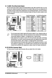
...the front and back panel audio connections simultaneously. Incorrect connection between the module connector and the motherboard header will be present on each wire instead of the motherboard header. If your chassis provides an AC'97 front panel audio module, refer to the ...For HD Front Panel Audio: For AC'97 Front Panel Audio: 10 9 Pin No. Definition 1 CD-L 1 2 GND 3 GND 4 CD-R GA-M68SM-S2L Motherboard - 26 - For information about connecting the front panel audio module that has different wire assignments, please contact the chassis manufacturer. 12) CD_IN (CD ...
...the front and back panel audio connections simultaneously. Incorrect connection between the module connector and the motherboard header will be present on each wire instead of the motherboard header. If your chassis provides an AC'97 front panel audio module, refer to the ...For HD Front Panel Audio: For AC'97 Front Panel Audio: 10 9 Pin No. Definition 1 CD-L 1 2 GND 3 GND 4 CD-R GA-M68SM-S2L Motherboard - 26 - For information about connecting the front panel audio module that has different wire assignments, please contact the chassis manufacturer. 12) CD_IN (CD ...


