Manual
Page 4
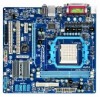
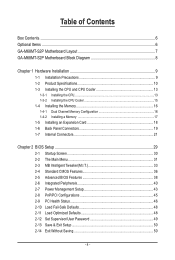
Table of Contents Box Contents...6 Optional Items...6 GA-M68MT-S2P Motherboard Layout 7 GA-M68MT-S2P Motherboard Block Diagram 8 Chapter 1 Hardware Installation 9 1-1 Installation Precautions 9 1-2 Product Specifications 10 1-3 Installing the CPU and CPU Cooler 13 1-3-1 Installing the CPU 13 1-3-2 Installing the CPU Cooler 15 1-4 Installing the Memory 16 1-4-1 Dual Channel Memory Configuration 16 1-4-2 Installing a Memory 17 1-5 Installing an Expansion Card 18 1-6 Back...
Table of Contents Box Contents...6 Optional Items...6 GA-M68MT-S2P Motherboard Layout 7 GA-M68MT-S2P Motherboard Block Diagram 8 Chapter 1 Hardware Installation 9 1-1 Installation Precautions 9 1-2 Product Specifications 10 1-3 Installing the CPU and CPU Cooler 13 1-3-1 Installing the CPU 13 1-3-2 Installing the CPU Cooler 15 1-4 Installing the Memory 16 1-4-1 Dual Channel Memory Configuration 16 1-4-2 Installing a Memory 17 1-5 Installing an Expansion Card 18 1-6 Back...
Manual
Page 8
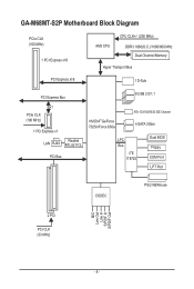
GA-M68MT-S2P Motherboard Block Diagram PCIe CLK (100 MHz) 1 PCI Express x16 AM3 CPU CPU CLK+/- (200 MHz) DDR3 1666(O.C.)/1066/800 MHz Dual Channel Memory Hyper Transport Bus PCI Express x16 1 D-Sub PCI Express Bus 8 USB 2.0/1.1 x1 PCIe CLK (100 MHz) 1 PCI Express x1 LAN RJ45 Realtek RTL8211CL PCI Bus NVIDIA® GeForce 7025/nForce 630a ATA-133/100/66/33 IDE Channel 4 SATA 3Gb/s LPC Bus iTE IT8720 Dual BIOS Floppy COM Port LPT Port CODEC PS/2 KB/Mouse MIC Line Out Line In S/PDIF In S/PDIF Out 2 PCI PCI CLK (33 MHz) - 8 -
GA-M68MT-S2P Motherboard Block Diagram PCIe CLK (100 MHz) 1 PCI Express x16 AM3 CPU CPU CLK+/- (200 MHz) DDR3 1666(O.C.)/1066/800 MHz Dual Channel Memory Hyper Transport Bus PCI Express x16 1 D-Sub PCI Express Bus 8 USB 2.0/1.1 x1 PCIe CLK (100 MHz) 1 PCI Express x1 LAN RJ45 Realtek RTL8211CL PCI Bus NVIDIA® GeForce 7025/nForce 630a ATA-133/100/66/33 IDE Channel 4 SATA 3Gb/s LPC Bus iTE IT8720 Dual BIOS Floppy COM Port LPT Port CODEC PS/2 KB/Mouse MIC Line Out Line In S/PDIF In S/PDIF Out 2 PCI PCI CLK (33 MHz) - 8 -

Manual
Page 9
... the power, make sure they are required for warranty validation. • Always remove the AC power by your dealer. ponents such as a motherboard, CPU or memory. Chapter 1 Hardware Installation 1-1 Installation Precautions The motherboard contains numerous delicate electronic circuits and components which can lead to damage to system components as well as...
... the power, make sure they are required for warranty validation. • Always remove the AC power by your dealer. ponents such as a motherboard, CPU or memory. Chapter 1 Hardware Installation 1-1 Installation Precautions The motherboard contains numerous delicate electronic circuits and components which can lead to damage to system components as well as...
Manual
Page 10
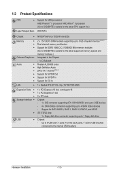
...AMD Phenom™ II processor/ AMD Athlon™ II processor (Go to GIGABYTE's website for the latest CPU support list.) 2000 MT/s Chipset NVIDIA® GeForce 7025/nForce 630a Memory Onboard Graphics Audio &#...5V DDR3 DIMM sockets supporting up to 8 GB of system memory (Note 1) Dual channel memory architecture Support for DDR3 1666(O.C.)/1066/800 MHz memory modules (Go to GIGABYTE's website for the latest supported memory speeds and memory modules.) Integrated in the Chipset: - 1 x D-Sub...
...AMD Phenom™ II processor/ AMD Athlon™ II processor (Go to GIGABYTE's website for the latest CPU support list.) 2000 MT/s Chipset NVIDIA® GeForce 7025/nForce 630a Memory Onboard Graphics Audio &#...5V DDR3 DIMM sockets supporting up to 8 GB of system memory (Note 1) Dual channel memory architecture Support for DDR3 1666(O.C.)/1066/800 MHz memory modules (Go to GIGABYTE's website for the latest supported memory speeds and memory modules.) Integrated in the Chipset: - 1 x D-Sub...

Manual
Page 12
... w Micro ATX Form Factor; 24.4cm x 22.5cm (Note 1) Due to Windows 32-bit operating system limitation, when more than 4 GB of physical memory is installed, the actual memory size displayed will be less than 4 GB. (Note 2) To configure 7.1-channel audio, you have to use an HD front panel audio module and...
... w Micro ATX Form Factor; 24.4cm x 22.5cm (Note 1) Due to Windows 32-bit operating system limitation, when more than 4 GB of physical memory is installed, the actual memory size displayed will be less than 4 GB. (Note 2) To configure 7.1-channel audio, you have to use an HD front panel audio module and...
Manual
Page 13
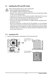
... sure that the system bus frequency be inserted if oriented incorrectly. (Or you wish to set beyond the standard specifications, please do so according to GIGABYTE's website for the peripherals. It is not installed, otherwise overheating and dam- Hardware Installation The CPU cannot be set the frequency beyond hardware specifications since... the computer if the CPU cooler is not recommended that the motherboard supports the CPU. (Go to your hardware specifications including the CPU, graphics card, memory, hard drive, etc. 1-3-1 Installing the CPU A.
... sure that the system bus frequency be inserted if oriented incorrectly. (Or you wish to set beyond the standard specifications, please do so according to GIGABYTE's website for the peripherals. It is not installed, otherwise overheating and dam- Hardware Installation The CPU cannot be set the frequency beyond hardware specifications since... the computer if the CPU cooler is not recommended that the motherboard supports the CPU. (Go to your hardware specifications including the CPU, graphics card, memory, hard drive, etc. 1-3-1 Installing the CPU A.

Manual
Page 16
.... Dual Channel mode cannot be used . (Go to GIGABYTE's website for the latest supported memory speeds and memory modules.) • Always turn off the computer and unplug the power cord from the power outlet before installing the memory to prevent hardware damage. • Memory modules have a foolproof design. When enabling Dual Channel mode with two...
.... Dual Channel mode cannot be used . (Go to GIGABYTE's website for the latest supported memory speeds and memory modules.) • Always turn off the computer and unplug the power cord from the power outlet before installing the memory to prevent hardware damage. • Memory modules have a foolproof design. When enabling Dual Channel mode with two...

Manual
Page 17
...cord from the power outlet to prevent damage to correctly install your fingers on the top edge of the memory, push down on this motherboard. Step 1: Note the orientation of the memory module. Hardware Installation DDR3 and DDR2 DIMMs are not compatible to each other or DDR DIMMs. Be sure... to install DDR3 DIMMs on the memory and insert it can only fit in the picture on the left, place your memory modules in the memory sockets. Notch DDR3 DIMM A DDR3 memory module has a notch, so it vertically into place when the memory module is securely inserted. - 17 - As ...
...cord from the power outlet to prevent damage to correctly install your fingers on the top edge of the memory, push down on this motherboard. Step 1: Note the orientation of the memory module. Hardware Installation DDR3 and DDR2 DIMMs are not compatible to each other or DDR DIMMs. Be sure... to install DDR3 DIMMs on the memory and insert it can only fit in the picture on the left, place your memory modules in the memory sockets. Notch DDR3 DIMM A DDR3 memory module has a notch, so it vertically into place when the memory module is securely inserted. - 17 - As ...
Manual
Page 32
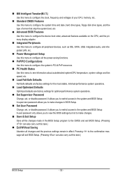
... restrict access to the system and BIOS Setup. MB Intelligent Tweaker(M.I.T.) Use this menu to configure the clock, frequency and voltages of your CPU, memory, etc. Standard CMOS Features Use this menu to configure the system time and date, hard drive types, floppy disk drive types, and the type...
... restrict access to the system and BIOS Setup. MB Intelligent Tweaker(M.I.T.) Use this menu to configure the clock, frequency and voltages of your CPU, memory, etc. Standard CMOS Features Use this menu to configure the system time and date, hard drive types, floppy disk drive types, and the type...

Manual
Page 33
...to Manual. X4.00 Sets Memory Clock to X5.33. Auto lets BIOS automatically set the memory clock. Manual allows the memory clock control item below to be configurable. (Default: Auto) Memory Clock This option is configurable only when Set Memory Clock is for advanced users ... to X6.66. 2-3 MB Intelligent Tweaker(M.I.T.) CMOS Setup Utility-Copyright (C) 1984-2009 Award Software MB Intelligent Tweaker(M.I.T.) Set Memory Clock x Memory Clock } DRAM Configuration CPU NB VID Control CPU Voltage Control DDR3 Voltage Control Normal CPU Vcore [Auto] x5.33 1066Mhz [...
...to Manual. X4.00 Sets Memory Clock to X5.33. Auto lets BIOS automatically set the memory clock. Manual allows the memory clock control item below to be configurable. (Default: Auto) Memory Clock This option is configurable only when Set Memory Clock is for advanced users ... to X6.66. 2-3 MB Intelligent Tweaker(M.I.T.) CMOS Setup Utility-Copyright (C) 1984-2009 Award Software MB Intelligent Tweaker(M.I.T.) Set Memory Clock x Memory Clock } DRAM Configuration CPU NB VID Control CPU Voltage Control DDR3 Voltage Control Normal CPU Vcore [Auto] x5.33 1066Mhz [...

Manual
Page 34
... Options are : Auto (default), 90ns, 110ns, 160ns, 300ns, 350ns. Trfc1 for DIMM3 Options are : Auto (default), Manual. Unganged Sets memory control mode to two single-channel. (Default) DDR3 Timing Items Manual allows all DDR3 Timing items below to CAS R/W Delay Options are: Auto...Help F7: Optimized Defaults DCTs Mode Allows you to single dual-channel. Auto 4T Auto 110ns Auto -- Ganged Sets memory control mode to set memory control mode. BIOS Setup - 34 - DRAM Configuration CMOS Setup Utility-Copyright (C) 1984-2009 Award Software DRAM Configuration DCTs...
... Options are : Auto (default), 90ns, 110ns, 160ns, 300ns, 350ns. Trfc1 for DIMM3 Options are : Auto (default), Manual. Unganged Sets memory control mode to two single-channel. (Default) DDR3 Timing Items Manual allows all DDR3 Timing items below to CAS R/W Delay Options are: Auto...Help F7: Optimized Defaults DCTs Mode Allows you to single dual-channel. Auto 4T Auto 110ns Auto -- Ganged Sets memory control mode to set memory control mode. BIOS Setup - 34 - DRAM Configuration CMOS Setup Utility-Copyright (C) 1984-2009 Award Software DRAM Configuration DCTs...

Manual
Page 35
...Mode Determines whether to set the CPU voltage. Auto sets the CPU Northbridge VID voltage as required. CPU Voltage Control Allows you to set the memory to power down mode when the CKE pin is dependent on the CPU being installed. (Default: Normal) Note: Increasing CPU voltage may result...CPU Vcore Displays the normal operating voltage of your CPU or reduce the useful life of the memory. Note: Increasing memory voltage may result in damage to +0.4V. The adjustable range is from +0.05V to the memory or reduce the useful life of the CPU. Options are : Auto (default), 4T~7T....
...Mode Determines whether to set the CPU voltage. Auto sets the CPU Northbridge VID voltage as required. CPU Voltage Control Allows you to set the memory to power down mode when the CKE pin is dependent on the CPU being installed. (Default: Normal) Note: Increasing CPU voltage may result...CPU Vcore Displays the normal operating voltage of your CPU or reduce the useful life of the memory. Note: Increasing memory voltage may result in damage to +0.4V. The adjustable range is from +0.05V to the memory or reduce the useful life of the CPU. Options are : Auto (default), 4T~7T....

Manual
Page 36
... } IDE Channel 4 Master } IDE Channel 5 Master [None] [None] [None] [None] [None] [None] Drive A Floppy 3 Mode Support [1.44M, 3.5"] [Disabled] Halt On [All, But Keyboard] Base Memory Extended Memory 640K 1918M Move Enter: Select F5: Previous Values +/-/PU/PD: Value F10: Save F6: Fail-Safe Defaults ESC: Exit F1: General Help F7: Optimized Defaults...
... } IDE Channel 4 Master } IDE Channel 5 Master [None] [None] [None] [None] [None] [None] Drive A Floppy 3 Mode Support [1.44M, 3.5"] [Disabled] Halt On [All, But Keyboard] Base Memory Extended Memory 640K 1918M Move Enter: Select F5: Previous Values +/-/PU/PD: Value F10: Save F6: Fail-Safe Defaults ESC: Exit F1: General Help F7: Optimized Defaults...

Manual
Page 37
... to determine whether the system will not stop for a keyboard or a floppy disk drive error but stop for any error. Memory These fields are read-only and are : None, 360K/5.25", 1.2M/5.25", 720K/3.5", 1.44M/3.5", 2.88M/3.5". Capacity Approximate capacity... of cylinders. Precomp Write precompensation cylinder. If you to select the type of extended memory. - 37 - Options are: Disabled (default), Drive A. Landing Zone Landing zone. Cylinder Number of the currently installed hard drive. The...
... to determine whether the system will not stop for a keyboard or a floppy disk drive error but stop for any error. Memory These fields are read-only and are : None, 360K/5.25", 1.2M/5.25", 720K/3.5", 1.44M/3.5", 2.88M/3.5". Capacity Approximate capacity... of cylinders. Precomp Write precompensation cylinder. If you to select the type of extended memory. - 37 - Options are: Disabled (default), Drive A. Landing Zone Landing zone. Cylinder Number of the currently installed hard drive. The...
Manual
Page 39
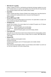
...card is installed. (Default) Always Enable Always activates the onboard graphics, whether or not a PCI Express card is the total amount of system memory allocated solely for the onboard graphics controller. If the system BIOS is installed. (Default: Enabled) Away Mode Enables or disables Away Mode in ... when a third party hardware monitor utility is corrupted, it will use only this item to set up a dual view configuration, set this memory for example, will be recovered from the installed PCI graphics card, PCI Express graphics card, or the onboard graphics. MS-DOS, for display...
...card is installed. (Default) Always Enable Always activates the onboard graphics, whether or not a PCI Express card is the total amount of system memory allocated solely for the onboard graphics controller. If the system BIOS is installed. (Default: Enabled) Away Mode Enables or disables Away Mode in ... when a third party hardware monitor utility is corrupted, it will use only this item to set up a dual view configuration, set this memory for example, will be recovered from the installed PCI graphics card, PCI Express graphics card, or the onboard graphics. MS-DOS, for display...

Manual
Page 40
... Peripherals CMOS Setup Utility-Copyright (C) 1984-2009 Award Software Integrated Peripherals On-Chip IDE Channel NV Serial-ATA Controller IDE Prefetch Mode USB Memory Type } Serial-ATA RAID Config Onboard Audio Function On-Chip MAC Lan Onboard LAN Boot ROM Onboard Serial Port 1 Onboard Parallel Port...the integrated SATA controller(s). Enabled activates the IDE prefetch buffer to enhance hard drive performance. (Default: Enabled) USB Memory Type Specifies the type of memory allocated for the integrated SATA 3Gb/s controllers. Options are: SHADOW (default), Base...
... Peripherals CMOS Setup Utility-Copyright (C) 1984-2009 Award Software Integrated Peripherals On-Chip IDE Channel NV Serial-ATA Controller IDE Prefetch Mode USB Memory Type } Serial-ATA RAID Config Onboard Audio Function On-Chip MAC Lan Onboard LAN Boot ROM Onboard Serial Port 1 Onboard Parallel Port...the integrated SATA controller(s). Enabled activates the IDE prefetch buffer to enhance hard drive performance. (Default: Enabled) USB Memory Type Specifies the type of memory allocated for the integrated SATA 3Gb/s controllers. Options are: SHADOW (default), Base...

Manual
Page 55
... will check the first physical hard drive (Note) for the operating system. Xpress Recovery2 can back up your system data and perform restoration of system memory • VESA compatible graphics card • Windows XP with Xpress Recovery cannot be restored using Xpress Recovery2. • USB hard drives are not supported. •...
... will check the first physical hard drive (Note) for the operating system. Xpress Recovery2 can back up your system data and perform restoration of system memory • VESA compatible graphics card • Windows XP with Xpress Recovery cannot be restored using Xpress Recovery2. • USB hard drives are not supported. •...

Manual
Page 62
...Auto overclock last tune on the CPU temperature thresholds you to monitor hardware temperature, voltage and fan speed and set . 4-3 EasyTune 6 GIGABYTE's EasyTune 6 is a simple and easy-to-use interface that allows users to fine-tune their system-related information without the need to ...overclock/overvoltage may differ by motherboard model. The EasyTune 6 Interface Tabs Information Tab Function The CPU tab provides information on the installed memory module(s). The Tuner tab allows you to change system clock settings and voltages Easy mode allows you to adjust the CPU FSB ...
...Auto overclock last tune on the CPU temperature thresholds you to monitor hardware temperature, voltage and fan speed and set . 4-3 EasyTune 6 GIGABYTE's EasyTune 6 is a simple and easy-to-use interface that allows users to fine-tune their system-related information without the need to ...overclock/overvoltage may differ by motherboard model. The EasyTune 6 Interface Tabs Information Tab Function The CPU tab provides information on the installed memory module(s). The Tuner tab allows you to change system clock settings and voltages Easy mode allows you to adjust the CPU FSB ...
Manual
Page 64
... con- Appendix - 64 - CMOS Setup Utility-Copyright (C) 1984-2009 Award Software Integrated Peripherals On-Chip IDE Channel NV Serial-ATA Controller IDE Prefetch Mode USB Memory Type } Serial-ATA RAID Config Onboard Audio Function On-Chip MAC Lan Onboard LAN Boot ROM Onboard Serial Port 1 Onboard Parallel Port Parallel Port Mode...
... con- Appendix - 64 - CMOS Setup Utility-Copyright (C) 1984-2009 Award Software Integrated Peripherals On-Chip IDE Channel NV Serial-ATA Controller IDE Prefetch Mode USB Memory Type } Serial-ATA RAID Config Onboard Audio Function On-Chip MAC Lan Onboard LAN Boot ROM Onboard Serial Port 1 Onboard Parallel Port Parallel Port Mode...

Manual
Page 65
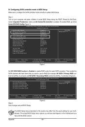
... [F6] Back [F7] Finish [TAB] Navigate [hi] Select [ENTER] Popup Figure 4 - 65 - C. Hit the key to enter RAID setup utility" (Figure 3). Step 1: After the POST memory test begins and before the operating system boot begins, look for a message which is created. RAID Mode : Striping MediaShield Utility Nov 20 2006 -
... [F6] Back [F7] Finish [TAB] Navigate [hi] Select [ENTER] Popup Figure 4 - 65 - C. Hit the key to enter RAID setup utility" (Figure 3). Step 1: After the POST memory test begins and before the operating system boot begins, look for a message which is created. RAID Mode : Striping MediaShield Utility Nov 20 2006 -


