Manual
Page 1
GA-M68M-S2P AM2+/AM2 socket motherboard for AMD Phenom™ II processor/ AMD Phenom™ processor/ AMD Athlon™ II processor/ AMD Athlon™ processor/ AMD Sempron™ processor User's Manual Rev. 1001 12ME-M68MS2P-1001R
GA-M68M-S2P AM2+/AM2 socket motherboard for AMD Phenom™ II processor/ AMD Phenom™ processor/ AMD Athlon™ II processor/ AMD Athlon™ processor/ AMD Sempron™ processor User's Manual Rev. 1001 12ME-M68MS2P-1001R
Manual
Page 2
Motherboard GA-M68M-S2P Nov. 9, 2009 Motherboard GA-M68M-S2P Nov. 9, 2009
Motherboard GA-M68M-S2P Nov. 9, 2009 Motherboard GA-M68M-S2P Nov. 9, 2009
Manual
Page 3
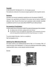
...prior notice. For example, "REV: 1.0" means the revision of the motherboard is the property of GIGABYTE. Copyright © 2009 GIGA-BYTE TECHNOLOGY CO., LTD. All rights reserved. No part of this product, GIGABYTE provides the following types of this manual may be reproduced, copied, ... protected by copyright laws and is 1.0. Example: For product-related information, check on our website at: http://www.gigabyte.com.tw Identifying Your Motherboard Revision The revision number on our website. The trademarks mentioned in the use of documentations: For detailed product...
...prior notice. For example, "REV: 1.0" means the revision of the motherboard is the property of GIGABYTE. Copyright © 2009 GIGA-BYTE TECHNOLOGY CO., LTD. All rights reserved. No part of this product, GIGABYTE provides the following types of this manual may be reproduced, copied, ... protected by copyright laws and is 1.0. Example: For product-related information, check on our website at: http://www.gigabyte.com.tw Identifying Your Motherboard Revision The revision number on our website. The trademarks mentioned in the use of documentations: For detailed product...
Manual
Page 4
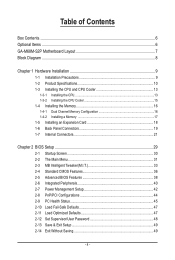
Table of Contents Box Contents...6 Optional Items...6 GA-M68M-S2P Motherboard Layout 7 Block Diagram...8 Chapter 1 Hardware Installation 9 1-1 Installation Precautions 9 1-2 Product Specifications 10 1-3 Installing the CPU and CPU Cooler 13 1-3-1 Installing the CPU 13 1-3-2 Installing the CPU ...
Table of Contents Box Contents...6 Optional Items...6 GA-M68M-S2P Motherboard Layout 7 Block Diagram...8 Chapter 1 Hardware Installation 9 1-1 Installation Precautions 9 1-2 Product Specifications 10 1-3 Installing the CPU and CPU Cooler 13 1-3-1 Installing the CPU 13 1-3-2 Installing the CPU ...
Manual
Page 6
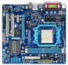
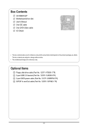
Box Contents GA-M68M-S2P Motherboard driver disk User's Manual One IDE cable One SATA 3Gb/s cable I/O Shield • The box contents above are subject to change without notice. • The motherboard image is for reference only and the actual items shall depend on the product package you obtain. Optional Items Floppy disk drive cable (Part No. 12CF1-1FD001-7*R) 2-port USB 2.0 bracket (Part No. 12CR1-1UB030-5*R) 2-port SATA power cable (Part No. 12CF1-2SERPW-0*R) S/PDIF In and Out cable (Part No. 12CR1-1SPINO-1*R) - 6 - The box contents are for reference only.
Box Contents GA-M68M-S2P Motherboard driver disk User's Manual One IDE cable One SATA 3Gb/s cable I/O Shield • The box contents above are subject to change without notice. • The motherboard image is for reference only and the actual items shall depend on the product package you obtain. Optional Items Floppy disk drive cable (Part No. 12CF1-1FD001-7*R) 2-port USB 2.0 bracket (Part No. 12CR1-1UB030-5*R) 2-port SATA power cable (Part No. 12CF1-2SERPW-0*R) S/PDIF In and Out cable (Part No. 12CR1-1SPINO-1*R) - 6 - The box contents are for reference only.
Manual
Page 9
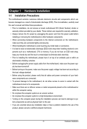
... • Always remove the AC power by your hardware components are connected. • To prevent damage to the motherboard, do not allow screws to come in contact with the motherboard circuit or its components. • Make sure there are connected tightly and securely. • When handling the... damaged as physical harm to the user. • If you do not remove or break motherboard S/N (Serial Number) sticker or warranty sticker provided by unplugging the power cord from the motherboard, make sure the power supply voltage has been set according to the local voltage standard. •...
... • Always remove the AC power by your hardware components are connected. • To prevent damage to the motherboard, do not allow screws to come in contact with the motherboard circuit or its components. • Make sure there are connected tightly and securely. • When handling the... damaged as physical harm to the user. • If you do not remove or break motherboard S/N (Serial Number) sticker or warranty sticker provided by unplugging the power cord from the motherboard, make sure the power supply voltage has been set according to the local voltage standard. •...

Manual
Page 12
... 3) Whether the CPU fan speed control function is supported will depend on the CPU cooler you install. (Note 4) Available functions in EasyTune may differ by motherboard model. Hardware Installation - 12 -
... 3) Whether the CPU fan speed control function is supported will depend on the CPU cooler you install. (Note 4) Available functions in EasyTune may differ by motherboard model. Hardware Installation - 12 -
Manual
Page 13
... grease on the surface of the CPU. • Do not turn on the computer if the CPU cooler is not recommended that the motherboard supports the CPU. (Go to GIGABYTE's website for the latest CPU support list.) • Always turn off the computer and unplug the power cord from the power outlet...
... grease on the surface of the CPU. • Do not turn on the computer if the CPU cooler is not recommended that the motherboard supports the CPU. (Go to GIGABYTE's website for the latest CPU support list.) • Always turn off the computer and unplug the power cord from the power outlet...
Manual
Page 14
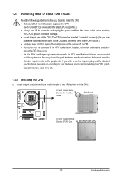
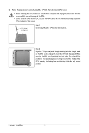
... on the CPU socket and gently insert the CPU into the fully locked position. Follow the steps below to correctly install the CPU into the motherboard CPU socket. • Before installing the CPU, make sure to turn off the computer and unplug the power cord from the power outlet to prevent...
... on the CPU socket and gently insert the CPU into the fully locked position. Follow the steps below to correctly install the CPU into the motherboard CPU socket. • Before installing the CPU, make sure to turn off the computer and unplug the power cord from the power outlet to prevent...
Manual
Page 15
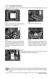
...frame. 1-3-2 Installing the CPU Cooler Follow the steps below to correctly install the CPU cooler on the CPU. (The following procedure uses the GIGABYTE cooler as the picture above shows) to lock into place. (Refer to your CPU cooler installation manual for instructions on installing the cooler.) Step... 5: Finally, attach the power connector of the CPU cooler to the CPU fan header (CPU_FAN) on the motherboard. Step 3: Hook the CPU cooler clip to the mounting lug on the surface of thermal grease on the retention frame. Use extreme care ...
...frame. 1-3-2 Installing the CPU Cooler Follow the steps below to correctly install the CPU cooler on the CPU. (The following procedure uses the GIGABYTE cooler as the picture above shows) to lock into place. (Refer to your CPU cooler installation manual for instructions on installing the cooler.) Step... 5: Finally, attach the power connector of the CPU cooler to the CPU fan header (CPU_FAN) on the motherboard. Step 3: Hook the CPU cooler clip to the mounting lug on the surface of thermal grease on the retention frame. Use extreme care ...
Manual
Page 16
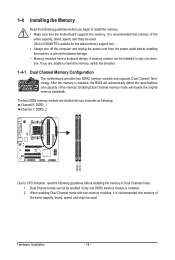
... hardware damage. • Memory modules have a foolproof design. Hardware Installation - 16 - A memory module can be used . (Go to GIGABYTE's website for the latest memory support list.) • Always turn off the computer and unplug the power cord from the power outlet before installing... the memory to insert the memory, switch the direction. 1-4-1 Dual Channel Memory Configuration This motherboard provides two DDR2 memory sockets and supports Dual Channel Technology. When enabling Dual Channel mode with two memory modules, it is installed,...
... hardware damage. • Memory modules have a foolproof design. Hardware Installation - 16 - A memory module can be used . (Go to GIGABYTE's website for the latest memory support list.) • Always turn off the computer and unplug the power cord from the power outlet before installing... the memory to insert the memory, switch the direction. 1-4-1 Dual Channel Memory Configuration This motherboard provides two DDR2 memory sockets and supports Dual Channel Technology. When enabling Dual Channel mode with two memory modules, it is installed,...

Manual
Page 17
... , make sure to turn off the computer and unplug the power cord from the power outlet to prevent damage to install DDR2 DIMMs on this motherboard.
... , make sure to turn off the computer and unplug the power cord from the power outlet to prevent damage to install DDR2 DIMMs on this motherboard.
Manual
Page 18
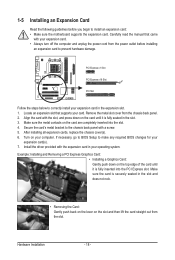
... the card until it is fully inserted into the slot. 4. If necessary, go to BIOS Setup to install an expansion card: • Make sure the motherboard supports the expansion card. Make sure the card is fully seated in the slot. 3. 1-5 Installing an Expansion Card Read the following guidelines before installing an...
... the card until it is fully inserted into the slot. 4. If necessary, go to BIOS Setup to install an expansion card: • Make sure the motherboard supports the expansion card. Make sure the card is fully seated in the slot. 3. 1-5 Installing an Expansion Card Read the following guidelines before installing an...
Manual
Page 20
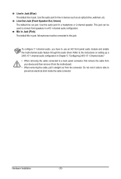
... optical drive, walkman, etc. Microphones must be used to a back panel connector, first remove the cable from your device and then remove it from the motherboard. • When removing the cable, pull it side to side to use an HD front panel audio module and enable the multi-channel audio feature...
... optical drive, walkman, etc. Microphones must be used to a back panel connector, first remove the cable from your device and then remove it from the motherboard. • When removing the cable, pull it side to side to use an HD front panel audio module and enable the multi-channel audio feature...

Manual
Page 21
..., make sure your devices are compliant with the connectors you wish to connect. • Before installing the devices, be sure to the connector on the motherboard. - 21 -
..., make sure your devices are compliant with the connectors you wish to connect. • Before installing the devices, be sure to the connector on the motherboard. - 21 -
Manual
Page 22
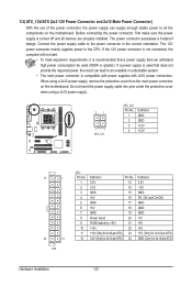
... power supply cable into pins under the protective cover when using a 2x12 power supply, remove the protective cover from the main power connector on the motherboard. When using a 2x10 power supply. 21 43 ATX_12V ATX_12V: Pin No. 1 2 3 4 Definition GND GND +12V +12V 13 1 24 12 ATX ATX: Pin No. 1 2 ... Installation - 22 - Before connecting the power connector, first make sure the power supply is turned off and all the components on the motherboard. The power connector possesses a foolproof design. If the 12V power connector is not connected, the computer will not start. • To...
... power supply cable into pins under the protective cover when using a 2x12 power supply, remove the protective cover from the main power connector on the motherboard. When using a 2x10 power supply. 21 43 ATX_12V ATX_12V: Pin No. 1 2 3 4 Definition GND GND +12V +12V 13 1 24 12 ATX ATX: Pin No. 1 2 ... Installation - 22 - Before connecting the power connector, first make sure the power supply is turned off and all the components on the motherboard. The power connector possesses a foolproof design. If the 12V power connector is not connected, the computer will not start. • To...
Manual
Page 23
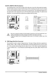
... the headers. 5) FDD (Floppy Disk Drive Connector) This connector is the ground wire). 3/4) CPU_FAN/SYS_FAN (Fan Headers) The motherboard has a 4-pin CPU fan header (CPU_FAN) and a 3-pin (SYS_FAN) system fan headers. The motherboard supports CPU fan speed control, which requires the use of different color. For purchasing the optional floppy disk drive...
... the headers. 5) FDD (Floppy Disk Drive Connector) This connector is the ground wire). 3/4) CPU_FAN/SYS_FAN (Fan Headers) The motherboard has a 4-pin CPU fan header (CPU_FAN) and a 3-pin (SYS_FAN) system fan headers. The motherboard supports CPU fan speed control, which requires the use of different color. For purchasing the optional floppy disk drive...

Manual
Page 26
...(L) 10 GND 10 NC • The front panel audio header supports HD audio by default. Pin No. Incorrect connection between the module connector and the motherboard header will be present on how to this header. Make sure the wire assignments of the module connector match the pin assignments of the front...CD_IN (CD In Connector) You may connect your chassis provides an AC'97 front panel audio module, refer to the instructions on both of the motherboard header. 9) F_AUDIO (Front Panel Audio Header) The front panel audio header supports Intel High Definition audio (HD) and AC'97 audio.
...(L) 10 GND 10 NC • The front panel audio header supports HD audio by default. Pin No. Incorrect connection between the module connector and the motherboard header will be present on how to this header. Make sure the wire assignments of the module connector match the pin assignments of the front...CD_IN (CD In Connector) You may connect your chassis provides an AC'97 front panel audio module, refer to the instructions on both of the motherboard header. 9) F_AUDIO (Front Panel Audio Header) The front panel audio header supports Intel High Definition audio (HD) and AC'97 audio.
Manual
Page 28
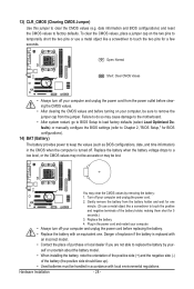
... information) in the CMOS when the computer is replaced with local environmental regulations. Turn off your computer, be accurate or may cause damage to the motherboard. • After system restart, go to BIOS Setup to load factory defaults (select Load Optimized Defaults) or manually configure the BIOS settings (refer to Chapter...
... information) in the CMOS when the computer is replaced with local environmental regulations. Turn off your computer, be accurate or may cause damage to the motherboard. • After system restart, go to BIOS Setup to load factory defaults (select Load Optimized Defaults) or manually configure the BIOS settings (refer to Chapter...
Manual
Page 29
...refer to Chapter 4, "BIOS Update Utilities." • Because BIOS flashing is potentially risky, if you do it is turned on the motherboard supplies the necessary power to the CMOS to keep the configuration values in system's failure to prevent system instability or other unexpected results. ...8226; BIOS will emit a beep code during system startup, saving system parameters and loading operating system, etc. To upgrade the BIOS, use either the GIGABYTE Q-Flash or @BIOS utility. • Q-Flash allows the user to clear the CMOS values.) - 29 - Refer to Chapter 5, "Troubleshooting," for...
...refer to Chapter 4, "BIOS Update Utilities." • Because BIOS flashing is potentially risky, if you do it is turned on the motherboard supplies the necessary power to the CMOS to keep the configuration values in system's failure to prevent system instability or other unexpected results. ...8226; BIOS will emit a beep code during system startup, saving system parameters and loading operating system, etc. To upgrade the BIOS, use either the GIGABYTE Q-Flash or @BIOS utility. • Q-Flash allows the user to clear the CMOS values.) - 29 - Refer to Chapter 5, "Troubleshooting," for...


