Manual
Page 1
GA-M61PME-S2 AM2 socket motherboard for AMD AthlonTM 64 FX processor/ AMD AthlonTM 64 X2 Dual-Core processor/ AMD AthlonTM 64 processor/AMD SempronTM processor User's Manual Rev. 2003 12ME-M61PMES2-2003R
GA-M61PME-S2 AM2 socket motherboard for AMD AthlonTM 64 FX processor/ AMD AthlonTM 64 X2 Dual-Core processor/ AMD AthlonTM 64 processor/AMD SempronTM processor User's Manual Rev. 2003 12ME-M61PMES2-2003R

Manual
Page 2
Motherboard GA-M61PME-S2 Jan. 16, 2008 Motherboard GA-M61PME-S2 Jan. 16, 2008
Motherboard GA-M61PME-S2 Jan. 16, 2008 Motherboard GA-M61PME-S2 Jan. 16, 2008
Manual
Page 3
... read or download the information on/from the Support\Motherboard\Technology Guide page on your motherboard revision before updating motherboard BIOS, drivers, or when looking for technical information. Check your motherboard looks like this product, GIGABYTE provides the following types of the motherboard is the property of GIGABYTE branded motherboards. is exclusively licensed to the specifications and features...
... read or download the information on/from the Support\Motherboard\Technology Guide page on your motherboard revision before updating motherboard BIOS, drivers, or when looking for technical information. Check your motherboard looks like this product, GIGABYTE provides the following types of the motherboard is the property of GIGABYTE branded motherboards. is exclusively licensed to the specifications and features...
Manual
Page 4
Table of Contents Box Contents ...6 OptionalItems...6 GA-M61PME-S2 Motherboard Layout 7 Block Diagram...8 Chapter 1 Hardware Installation 9 1-1 Installation Precautions 9 1-2 Product Specifications 10 1-3 Installing the CPU and CPU Cooler 12 1-3-1 Installing the CPU 12 1-3-2 Installing the CPU ...
Table of Contents Box Contents ...6 OptionalItems...6 GA-M61PME-S2 Motherboard Layout 7 Block Diagram...8 Chapter 1 Hardware Installation 9 1-1 Installation Precautions 9 1-2 Product Specifications 10 1-3 Installing the CPU and CPU Cooler 12 1-3-1 Installing the CPU 12 1-3-2 Installing the CPU ...
Manual
Page 6
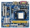
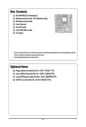
Box Contents GA-M61PME-S2 motherboard Motherboard driver disk (For Windows Vista) Motherboard driver disk User's Manual One IDE cable One SATA 3Gb/s cable I/O Shield • The box contents above are subject to change without notice. • The motherboard image is for reference only and the actual items shall depend on product package you obtain. The box contents...
Box Contents GA-M61PME-S2 motherboard Motherboard driver disk (For Windows Vista) Motherboard driver disk User's Manual One IDE cable One SATA 3Gb/s cable I/O Shield • The box contents above are subject to change without notice. • The motherboard image is for reference only and the actual items shall depend on product package you obtain. The box contents...
Manual
Page 9
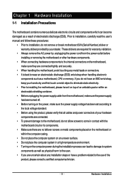
... within an electrostatic shielding container. • Before unplugging the power supply cable from the power outlet before installing or removing the motherboard or other hardware components. • When connecting hardware components to the internal connectors on the power, make sure the power supply... voltage has been set according to wear an electrostatic discharge (ESD) wrist strap when handling electronic components such as a motherboard, CPU or memory. These stickers are required for warranty validation. • Always remove the AC power by your hands dry and first...
... within an electrostatic shielding container. • Before unplugging the power supply cable from the power outlet before installing or removing the motherboard or other hardware components. • When connecting hardware components to the internal connectors on the power, make sure the power supply... voltage has been set according to wear an electrostatic discharge (ESD) wrist strap when handling electronic components such as a motherboard, CPU or memory. These stickers are required for warranty validation. • Always remove the AC power by your hands dry and first...
Manual
Page 10
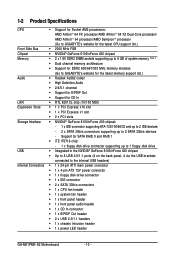
... supporting up to 8 GB of system memory (Note 1) Dual channel memory architecture Support for DDR2 800/667/533 MHz memory modules (Go to GIGABYTE's website for the latest memory support list.) Audio Realtek AL662 codec High Definition Audio 2/4/5.1-channel Support for S/PDIF Out ... header 1 x front panel audio header 1 x CD In connector 1 x S/PDIF Out header 2 x USB 2.0/1.1 headers 1 x chassis intrusion header 1 x power LED header GA-M61PME-S2 Motherboard - 10 -
... supporting up to 8 GB of system memory (Note 1) Dual channel memory architecture Support for DDR2 800/667/533 MHz memory modules (Go to GIGABYTE's website for the latest memory support list.) Audio Realtek AL662 codec High Definition Audio 2/4/5.1-channel Support for S/PDIF Out ... header 1 x front panel audio header 1 x CD In connector 1 x S/PDIF Out header 2 x USB 2.0/1.1 headers 1 x chassis intrusion header 1 x power LED header GA-M61PME-S2 Motherboard - 10 -
Manual
Page 11
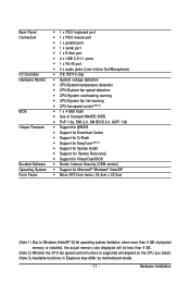
.... (Note 2) Whether the CPU fan speed control function is supported will depend on the CPU you install. (Note 3) Available functions in Easytune may differ by motherboard model. - 11 -
.... (Note 2) Whether the CPU fan speed control function is supported will depend on the CPU you install. (Note 3) Available functions in Easytune may differ by motherboard model. - 11 -

Manual
Page 12
... even and thin layer of thermal grease on the surface of the Socket AM2 CPU Socket A Small Triangle Marking Denotes CPU Pin One AM2 CPU GA-M61PME-S2 Motherboard - 12 - It is not installed, otherwise overheating and damage of the CPU may occur. • Set the CPU host frequency in accordance with the CPU... the CPU to prevent hardware damage. • Locate the pin one (denoted by a small triangle) of the CPU socket and the CPU. mended that the motherboard supports the CPU. (Go to GIGABYTE's website for the peripherals.
... even and thin layer of thermal grease on the surface of the Socket AM2 CPU Socket A Small Triangle Marking Denotes CPU Pin One AM2 CPU GA-M61PME-S2 Motherboard - 12 - It is not installed, otherwise overheating and damage of the CPU may occur. • Set the CPU host frequency in accordance with the CPU... the CPU to prevent hardware damage. • Locate the pin one (denoted by a small triangle) of the CPU socket and the CPU. mended that the motherboard supports the CPU. (Go to GIGABYTE's website for the peripherals.

Manual
Page 13
... force the CPU into their holes. B. Step 2: Align the CPU pin one finger down on the CPU socket and gently insert the CPU into the motherboard CPU socket. Hardware Installation Before installing the CPU, make sure to turn off the computer and unplug the power cord from the power outlet to...
... force the CPU into their holes. B. Step 2: Align the CPU pin one finger down on the CPU socket and gently insert the CPU into the motherboard CPU socket. Hardware Installation Before installing the CPU, make sure to turn off the computer and unplug the power cord from the power outlet to...

Manual
Page 14
... CPU. GA-M61PME-S2 Motherboard - 14 - Step 3: Hook the CPU cooler clip to the mounting lug on one side of the CPU cooler to the CPU fan header (CPU_FAN) on the motherboard. 1-3-2 Installing the CPU Cooler Follow the steps below to correctly install the CPU cooler on the CPU. (The following procedure uses the GIGABYTE cooler...
... CPU. GA-M61PME-S2 Motherboard - 14 - Step 3: Hook the CPU cooler clip to the mounting lug on one side of the CPU cooler to the CPU fan header (CPU_FAN) on the motherboard. 1-3-2 Installing the CPU Cooler Follow the steps below to correctly install the CPU cooler on the CPU. (The following procedure uses the GIGABYTE cooler...
Manual
Page 15
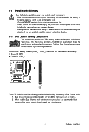
...Due to install the memory: • Make sure that memory of the same capacity, brand, speed, and chips be used . (Go to GIGABYTE's website for the latest memory support list.) • Always turn off the computer and unplug the power cord from the power outlet before installing ...the memory in only one DDR2 memory module is recommended that the motherboard supports the memory. When enabling Dual Channel mode with two memory modules, it is installed. 2. Enabling Dual Channel memory mode will automatically...
...Due to install the memory: • Make sure that memory of the same capacity, brand, speed, and chips be used . (Go to GIGABYTE's website for the latest memory support list.) • Always turn off the computer and unplug the power cord from the power outlet before installing ...the memory in only one DDR2 memory module is recommended that the motherboard supports the memory. When enabling Dual Channel mode with two memory modules, it is installed. 2. Enabling Dual Channel memory mode will automatically...

Manual
Page 16
... , make sure to turn off the computer and unplug the power cord from the power outlet to prevent damage to install DDR2 DIMMs on this motherboard. DDR2 DIMMs are not compatible to DDR DIMMs. Be sure to the memory module. Spread the retaining clips at both ends of the socket will... of the memory, push down on the socket. Place the memory module on the memory and insert it can only fit in the memory sockets. GA-M61PME-S2 Motherboard - 16 - Notch DDR2 DIMM A DDR2 memory module has a notch, so it vertically into place when the memory module is securely inserted.
... , make sure to turn off the computer and unplug the power cord from the power outlet to prevent damage to install DDR2 DIMMs on this motherboard. DDR2 DIMMs are not compatible to DDR DIMMs. Be sure to the memory module. Spread the retaining clips at both ends of the socket will... of the memory, push down on the socket. Place the memory module on the memory and insert it can only fit in the memory sockets. GA-M61PME-S2 Motherboard - 16 - Notch DDR2 DIMM A DDR2 memory module has a notch, so it vertically into place when the memory module is securely inserted.

Manual
Page 17
... the card's metal bracket to correctly install your operating system. If necessary, go to BIOS Setup to install an expansion card: • Make sure the motherboard supports the expansion card. Hardware Installation 1-5 Installing an Expansion Card Read the following guidelines before installing an expansion card to prevent hardware damage. Carefully read...
... the card's metal bracket to correctly install your operating system. If necessary, go to BIOS Setup to install an expansion card: • Make sure the motherboard supports the expansion card. Hardware Installation 1-5 Installing an Expansion Card Read the following guidelines before installing an expansion card to prevent hardware damage. Carefully read...
Manual
Page 18
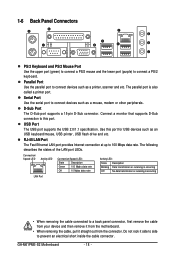
... and etc. Parallel Port Use the parallel port to a back panel connector, first remove the cable from your device and then remove it from the motherboard. • When removing the cable, pull it side to side to connect a PS/2 keyboard. Use this port. The parallel port is occurring LAN Port •..., modem or other peripherals. Serial Port Use the serial port to 100 Mbps data rate. D-Sub Port The D-Sub port supports a 15-pin D-Sub connector. GA-M61PME-S2 Motherboard - 18 -
... and etc. Parallel Port Use the parallel port to a back panel connector, first remove the cable from your device and then remove it from the motherboard. • When removing the cable, pull it side to side to connect a PS/2 keyboard. Use this port. The parallel port is occurring LAN Port •..., modem or other peripherals. Serial Port Use the serial port to 100 Mbps data rate. D-Sub Port The D-Sub port supports a 15-pin D-Sub connector. GA-M61PME-S2 Motherboard - 18 -
Manual
Page 20
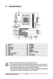
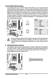
GA-M61PME-S2 Motherboard - 20 - 1-7 Internal Connectors 1 3 15 11 16 9 12 13 1) ATX_12V 2) ATX 3) CPU_FAN 4) SYS_FAN 5) FDD 6) IDE 7) SATAII 0 / SATAII 1 8) PWR_LED 2 6 7 14 5 48 10 9) BATTERY 10) F_PANEL 11) F_AUDIO ..., make sure your devices are compliant with the connectors you wish to connect. • Before installing the devices, be sure to the connector on the motherboard. Unplug the power cord from the power outlet to prevent damage to the devices. • After installing the device and before connecting external devices: •...
GA-M61PME-S2 Motherboard - 20 - 1-7 Internal Connectors 1 3 15 11 16 9 12 13 1) ATX_12V 2) ATX 3) CPU_FAN 4) SYS_FAN 5) FDD 6) IDE 7) SATAII 0 / SATAII 1 8) PWR_LED 2 6 7 14 5 48 10 9) BATTERY 10) F_PANEL 11) F_AUDIO ..., make sure your devices are compliant with the connectors you wish to connect. • Before installing the devices, be sure to the connector on the motherboard. Unplug the power cord from the power outlet to prevent damage to the devices. • After installing the device and before connecting external devices: •...
Manual
Page 21
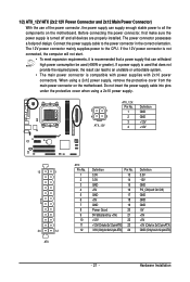
... power, the result can lead to an unstable or unbootable system. • The main power connector is turned off and all the components on the motherboard. The power connector possesses a foolproof design. When using a 2x10 power supply. 2 1 4 3 ATX_12V ATX_12V: Pin No. 1 2 3 4 Definition GND GND +12V +12V 13 1 24 12 ATX ATX... power supply cable into pins under the protective cover when using a 2x12 power supply, remove the protective cover from the main power connector on the motherboard. Connect the power supply cable to the CPU.
... power, the result can lead to an unstable or unbootable system. • The main power connector is turned off and all the components on the motherboard. The power connector possesses a foolproof design. When using a 2x10 power supply. 2 1 4 3 ATX_12V ATX_12V: Pin No. 1 2 3 4 Definition GND GND +12V +12V 13 1 24 12 ATX ATX... power supply cable into pins under the protective cover when using a 2x12 power supply, remove the protective cover from the main power connector on the motherboard. Connect the power supply cable to the CPU.
Manual
Page 22
... to connect a floppy disk drive. The pin 1 of the cable is used to connect it is the ground wire. The motherboard supports CPU/system fan speed control, which requires the use of different color. 33 1 34 2 GA-M61PME-S2 Motherboard - 22 - When connecting a fan cable, be installed inside the chassis. 3/4) CPU_FAN/SYS_FAN (Fan Headers) The...
... to connect a floppy disk drive. The pin 1 of the cable is used to connect it is the ground wire. The motherboard supports CPU/system fan speed control, which requires the use of different color. 33 1 34 2 GA-M61PME-S2 Motherboard - 22 - When connecting a fan cable, be installed inside the chassis. 3/4) CPU_FAN/SYS_FAN (Fan Headers) The...
Manual
Page 24
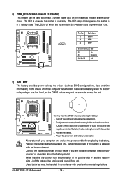
... computer and unplug the power cord before replacing the battery. • Replace the battery with local environmental regulations. Definition 1 MPD+ 2 MPD- 1 3 MPD- Replace the battery. 4. GA-M61PME-S2 Motherboard - 24 - System Status LED S0 On S1 Blinking S3/S4/S5 Off 9) BATTERY The battery provides power to keep the values (such as BIOS configurations...
... computer and unplug the power cord before replacing the battery. • Replace the battery with local environmental regulations. Definition 1 MPD+ 2 MPD- 1 3 MPD- Replace the battery. 4. GA-M61PME-S2 Motherboard - 24 - System Status LED S0 On S1 Blinking S3/S4/S5 Off 9) BATTERY The battery provides power to keep the values (such as BIOS configurations...

Manual
Page 26
... match the pin assignments of the front and back panel audio connections simultaneously. Incorrect connection between the module connector and the motherboard header will be present on each wire instead of a single plug. If you want to mute the back panel audio ...2/4/5.1-Channel Audio." • Audio signals will make the device unable to work or even damage it. Definition 1 CD-L 2 GND 1 3 GND 4 CD-R GA-M61PME-S2 Motherboard - 26 - 11) F_AUDIO (Front Panel Audio Header) The front panel audio header supports Intel High Definition audio (HD) and AC'97 audio. Definition 1 ...
... match the pin assignments of the front and back panel audio connections simultaneously. Incorrect connection between the module connector and the motherboard header will be present on each wire instead of a single plug. If you want to mute the back panel audio ...2/4/5.1-Channel Audio." • Audio signals will make the device unable to work or even damage it. Definition 1 CD-L 2 GND 1 3 GND 4 CD-R GA-M61PME-S2 Motherboard - 26 - 11) F_AUDIO (Front Panel Audio Header) The front panel audio header supports Intel High Definition audio (HD) and AC'97 audio. Definition 1 ...


