Manual
Page 1
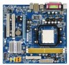
GA-M61PME-S2 AM2 socket motherboard for AMD AthlonTM 64 FX processor/ AMD AthlonTM 64 X2 Dual-Core processor/ AMD AthlonTM 64 processor/AMD SempronTM processor User's Manual Rev. 2003 12ME-M61PMES2-2003R
GA-M61PME-S2 AM2 socket motherboard for AMD AthlonTM 64 FX processor/ AMD AthlonTM 64 X2 Dual-Core processor/ AMD AthlonTM 64 processor/AMD SempronTM processor User's Manual Rev. 2003 12ME-M61PMES2-2003R

Manual
Page 2
Motherboard GA-M61PME-S2 Jan. 16, 2008 Motherboard GA-M61PME-S2 Jan. 16, 2008
Motherboard GA-M61PME-S2 Jan. 16, 2008 Motherboard GA-M61PME-S2 Jan. 16, 2008
Manual
Page 4
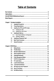
Table of Contents Box Contents ...6 OptionalItems...6 GA-M61PME-S2 Motherboard Layout 7 Block Diagram...8 Chapter 1 Hardware Installation 9 1-1 Installation Precautions 9 1-2 Product Specifications 10 1-3 Installing the CPU and CPU Cooler 12 1-3-1 Installing the CPU 12 1-3-2 Installing the ...
Table of Contents Box Contents ...6 OptionalItems...6 GA-M61PME-S2 Motherboard Layout 7 Block Diagram...8 Chapter 1 Hardware Installation 9 1-1 Installation Precautions 9 1-2 Product Specifications 10 1-3 Installing the CPU and CPU Cooler 12 1-3-1 Installing the CPU 12 1-3-2 Installing the ...
Manual
Page 6
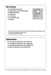
...-1UB030-5*R) 2-port SATA power cable (Part No. 12CF1-2SERPW-0*R) S/PDIF out cable (Part No. 12CR1-1SPOUT-0*R) - 6 - The box contents are for reference only. Box Contents GA-M61PME-S2 motherboard Motherboard driver disk (For Windows Vista) Motherboard driver disk User's Manual One IDE cable One SATA 3Gb/s cable I/O Shield • The box contents above...
...-1UB030-5*R) 2-port SATA power cable (Part No. 12CF1-2SERPW-0*R) S/PDIF out cable (Part No. 12CR1-1SPOUT-0*R) - 6 - The box contents are for reference only. Box Contents GA-M61PME-S2 motherboard Motherboard driver disk (For Windows Vista) Motherboard driver disk User's Manual One IDE cable One SATA 3Gb/s cable I/O Shield • The box contents above...
Manual
Page 10
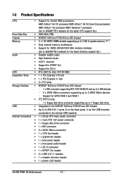
... supporting up to 8 GB of system memory (Note 1) Dual channel memory architecture Support for DDR2 800/667/533 MHz memory modules (Go to GIGABYTE's website for the latest memory support list.) Audio Realtek AL662 codec High Definition Audio 2/4/5.1-channel Support for S/PDIF Out ...header 1 x front panel audio header 1 x CD In connector 1 x S/PDIF Out header 2 x USB 2.0/1.1 headers 1 x chassis intrusion header 1 x power LED header GA-M61PME-S2 Motherboard - 10 -
... supporting up to 8 GB of system memory (Note 1) Dual channel memory architecture Support for DDR2 800/667/533 MHz memory modules (Go to GIGABYTE's website for the latest memory support list.) Audio Realtek AL662 codec High Definition Audio 2/4/5.1-channel Support for S/PDIF Out ...header 1 x front panel audio header 1 x CD In connector 1 x S/PDIF Out header 2 x USB 2.0/1.1 headers 1 x chassis intrusion header 1 x power LED header GA-M61PME-S2 Motherboard - 10 -

Manual
Page 12
... to GIGABYTE's website for the peripherals. The CPU cannot be set the frequency beyond hardware specifications since it does not meet the standard requirements for the latest CPU support list.) • Always turn on the surface of the Socket AM2 CPU Socket A Small Triangle Marking Denotes CPU Pin One AM2 CPU GA-M61PME-S2...
... to GIGABYTE's website for the peripherals. The CPU cannot be set the frequency beyond hardware specifications since it does not meet the standard requirements for the latest CPU support list.) • Always turn on the surface of the Socket AM2 CPU Socket A Small Triangle Marking Denotes CPU Pin One AM2 CPU GA-M61PME-S2...

Manual
Page 14
Step 3: Hook the CPU cooler clip to the mounting lug on the retention frame. GA-M61PME-S2 Motherboard - 14 - Inadequately removing the CPU cooler may adhere to the CPU. On the other side, push straight down on the the CPU cooler clip ... damage the CPU. 1-3-2 Installing the CPU Cooler Follow the steps below to correctly install the CPU cooler on the CPU. (The following procedure uses the GIGABYTE cooler as the picture above shows) to lock into place. (Refer to your CPU cooler installation manual for instructions on installing the cooler.) Step 5: Finally...
Step 3: Hook the CPU cooler clip to the mounting lug on the retention frame. GA-M61PME-S2 Motherboard - 14 - Inadequately removing the CPU cooler may adhere to the CPU. On the other side, push straight down on the the CPU cooler clip ... damage the CPU. 1-3-2 Installing the CPU Cooler Follow the steps below to correctly install the CPU cooler on the CPU. (The following procedure uses the GIGABYTE cooler as the picture above shows) to lock into place. (Refer to your CPU cooler installation manual for instructions on installing the cooler.) Step 5: Finally...

Manual
Page 16
... motherboard. DDR2 DIMMs are not compatible to DDR DIMMs. Be sure to the memory module. Step 2: The clips at both ends of the memory socket. GA-M61PME-S2 Motherboard - 16 - Spread the retaining clips at both ends of the socket will snap into the memory socket.
... motherboard. DDR2 DIMMs are not compatible to DDR DIMMs. Be sure to the memory module. Step 2: The clips at both ends of the memory socket. GA-M61PME-S2 Motherboard - 16 - Spread the retaining clips at both ends of the socket will snap into the memory socket.
Manual
Page 18
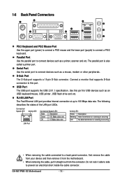
... or receiving is occurring Off No data transmission or receiving is also called a printer port. The following describes the states of the LAN port LEDs. GA-M61PME-S2 Motherboard - 18 - Use this port. 1-6 Back Panel Connectors PS/2 Keyboard and PS/2 Mouse Port Use the upper port (green) to connect a PS/2 mouse and the...
... or receiving is occurring Off No data transmission or receiving is also called a printer port. The following describes the states of the LAN port LEDs. GA-M61PME-S2 Motherboard - 18 - Use this port. 1-6 Back Panel Connectors PS/2 Keyboard and PS/2 Mouse Port Use the upper port (green) to connect a PS/2 mouse and the...
Manual
Page 20
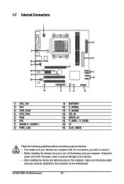
... devices are compliant with the connectors you wish to connect. • Before installing the devices, be sure to turn off the devices and your computer. GA-M61PME-S2 Motherboard - 20 -
... devices are compliant with the connectors you wish to connect. • Before installing the devices, be sure to turn off the devices and your computer. GA-M61PME-S2 Motherboard - 20 -
Manual
Page 22
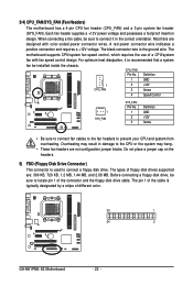
... CPU or the system may result in the correct orientation. For optimum heat dissipation, it in damage to locate pin 1 of different color. 33 1 34 2 GA-M61PME-S2 Motherboard - 22 - When connecting a fan cable, be sure to connect it is typically designated by a stripe of the connector and the floppy disk drive cable...
... CPU or the system may result in the correct orientation. For optimum heat dissipation, it in damage to locate pin 1 of different color. 33 1 34 2 GA-M61PME-S2 Motherboard - 22 - When connecting a fan cable, be sure to connect it is typically designated by a stripe of the connector and the floppy disk drive cable...
Manual
Page 24
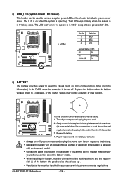
.... • When installing the battery, note the orientation of the positive side (+) and the negative side (-) of the battery holder, making them short for 5 seconds.) 3. GA-M61PME-S2 Motherboard - 24 - The LED keeps blinking when the system is replaced with an equivalent one minute. (Or use a metal object like a screwdriver to touch the...
.... • When installing the battery, note the orientation of the positive side (+) and the negative side (-) of the battery holder, making them short for 5 seconds.) 3. GA-M61PME-S2 Motherboard - 24 - The LED keeps blinking when the system is replaced with an equivalent one minute. (Or use a metal object like a screwdriver to touch the...

Manual
Page 26
... via the audio software in Chapter 5, "Configuring 2/4/5.1-Channel Audio." • Audio signals will make the device unable to the header. Definition 1 CD-L 2 GND 1 3 GND 4 CD-R GA-M61PME-S2 Motherboard - 26 - Make sure the wire assignments of the module connector match the pin assignments of the front and back panel audio connections simultaneously. If...
... via the audio software in Chapter 5, "Configuring 2/4/5.1-Channel Audio." • Audio signals will make the device unable to the header. Definition 1 CD-L 2 GND 1 3 GND 4 CD-R GA-M61PME-S2 Motherboard - 26 - Make sure the wire assignments of the module connector match the pin assignments of the front and back panel audio connections simultaneously. If...
Manual
Page 28
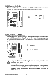
... feature that detects if the chassis cover has been removed. date information and BIOS configurations) and reset the CMOS values to clear the CMOS values (e.g. GA-M61PME-S2 Motherboard - 28 - Failure to do so may cause damage to the motherboard. • After system restart, go to BIOS Setup to load factory defaults (select...
... feature that detects if the chassis cover has been removed. date information and BIOS configurations) and reset the CMOS values to clear the CMOS values (e.g. GA-M61PME-S2 Motherboard - 28 - Failure to do so may cause damage to the motherboard. • After system restart, go to BIOS Setup to load factory defaults (select...
Manual
Page 30
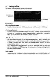
M61PME-S2 D1a . . . . : BIOS Setup/Q-Flash : XpressRecovery2 : Boot Menu : Qflash 12/17/2007-NV-MCP61-6A61KG09C-00 Function Keys Function Keys: : BIOS Setup/Q-Flash Press the key ... device configured in Boot Menu is effective for subsequent access to accept. You can be based on BIOS Setup settings. To exit Boot Menu, press . GA-M61PME-S2 Motherboard - 30 - Note: The setting in Boot Menu. In Boot Menu, use the up hard drive data using the motherboard driver disk, the key can...
M61PME-S2 D1a . . . . : BIOS Setup/Q-Flash : XpressRecovery2 : Boot Menu : Qflash 12/17/2007-NV-MCP61-6A61KG09C-00 Function Keys Function Keys: : BIOS Setup/Q-Flash Press the key ... device configured in Boot Menu is effective for subsequent access to accept. You can be based on BIOS Setup settings. To exit Boot Menu, press . GA-M61PME-S2 Motherboard - 30 - Note: The setting in Boot Menu. In Boot Menu, use the up hard drive data using the motherboard driver disk, the key can...
Manual
Page 32
... , or disable password. A supervisor password allows you to restrict access to the confirmation message will exit BIOS Setup. (Pressing can also carry out this task.) GA-M61PME-S2 Motherboard - 32 - Pressing to the system and BIOS Setup. It allows you to the CMOS and exit BIOS Setup. (Pressing can also carry out this...
... , or disable password. A supervisor password allows you to restrict access to the confirmation message will exit BIOS Setup. (Pressing can also carry out this task.) GA-M61PME-S2 Motherboard - 32 - Pressing to the system and BIOS Setup. It allows you to the CMOS and exit BIOS Setup. (Pressing can also carry out this...
Manual
Page 34
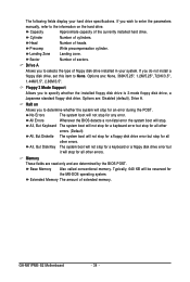
..., But Diskette The system boot will not stop for the MS-DOS operating system. Memory These fields are read-only and are : Disabled (default), Drive A. GA-M61PME-S2 Motherboard - 34 - Precomp Write precompensation cylinder. Sector Number of the currently installed hard drive. Options are determined by the BIOS POST. All, But Disk/Key...
..., But Diskette The system boot will not stop for the MS-DOS operating system. Memory These fields are read-only and are : Disabled (default), Drive A. GA-M61PME-S2 Motherboard - 34 - Precomp Write precompensation cylinder. Sector Number of the currently installed hard drive. Options are determined by the BIOS POST. All, But Disk/Key...
Manual
Page 36
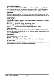
.... This feature allows your hard drive. PEG Sets PCI Express graphics card as the first display. (Default) Frame Buffer Size Frame buffer size is installed. GA-M61PME-S2 Motherboard - 36 - Options are: 32M, 64M (default), 128M, 256M, Disabled. PCI Slot Sets the PCI graphics card as the first display. Onboard VGA Sets the...
.... This feature allows your hard drive. PEG Sets PCI Express graphics card as the first display. (Default) Frame Buffer Size Frame buffer size is installed. GA-M61PME-S2 Motherboard - 36 - Options are: 32M, 64M (default), 128M, 256M, Disabled. PCI Slot Sets the PCI graphics card as the first display. Onboard VGA Sets the...
Manual
Page 38
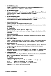
... RAID for individual SATA channel. (Default: Disabled) NV SATA 1 Primary RAID Enables or disables RAID for the first channel of the integrated SATA 3Gb/s controller. GA-M61PME-S2 Motherboard - 38 - This item is configurable only if the NV SATA RAID function item is set this item to activate the boot ROM integrated with...
... RAID for individual SATA channel. (Default: Disabled) NV SATA 1 Primary RAID Enables or disables RAID for the first channel of the integrated SATA 3Gb/s controller. GA-M61PME-S2 Motherboard - 38 - This item is configurable only if the NV SATA RAID function item is set this item to activate the boot ROM integrated with...
Manual
Page 40
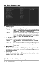
... Power-On by a wake-up signal from a PCI or PCIe device. Instant-Off Press the power button and then the system will enter suspend mode. GA-M61PME-S2 Motherboard - 40 - The system can be turned off the system. Note: To use this function, you need an ATX power supply providing at any time...
... Power-On by a wake-up signal from a PCI or PCIe device. Instant-Off Press the power button and then the system will enter suspend mode. GA-M61PME-S2 Motherboard - 40 - The system can be turned off the system. Note: To use this function, you need an ATX power supply providing at any time...


