Manual
Page 4
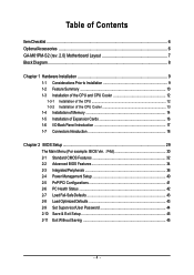
Table of Contents ItemChecklist ...6 OptionalAccessories ...6 GA-M61PM-S2 (rev. 2.0) Motherboard Layout 7 Block Diagram ...8 Chapter 1 Hardware Installation 9 1-1 Considerations Prior to Installation 9 1-2 Feature Summary 10 1-3 Installation of the CPU and CPU Cooler 12 1-3-1 Installation of the CPU 12 1-3-2 Installation of the CPU Cooler 13 1-4 Installation of Memory 14 1-5 Installation of Expansion Cards 16 1-6 I/O Back Panel Introduction 17 1-7 Connectors Introduction 18...
Table of Contents ItemChecklist ...6 OptionalAccessories ...6 GA-M61PM-S2 (rev. 2.0) Motherboard Layout 7 Block Diagram ...8 Chapter 1 Hardware Installation 9 1-1 Considerations Prior to Installation 9 1-2 Feature Summary 10 1-3 Installation of the CPU and CPU Cooler 12 1-3-1 Installation of the CPU 12 1-3-2 Installation of the CPU Cooler 13 1-4 Installation of Memory 14 1-5 Installation of Expansion Cards 16 1-6 I/O Back Panel Introduction 17 1-7 Connectors Introduction 18...

Manual
Page 8
Block Diagram PCIe CLK (100 MHz) VGA AMD Socket AM2 CPU CPU CLK+/-(200 MHz) DDRII 800/667/533/400 MHz DIMM Dual Channel Memory Hyper Transport Bus PCI Express x16 LAN RJ45 PCI Express x1 Bus x1 PCIe CLK (100 MHz) 1 PCI Express x1 RTL8211 PCI Bus TSB43AB23 4 SATA 3Gb/s nVIDIA® GeForce 6100/ nForce 430 LPC BUS ATA 33/66/100/133 IDE Channel BIOS Floppy IT8716 LPT Port COM Ports PS/2 Keyboard/ Mouse CODEC 3 IEEE 1394a Surround Speaker Out Center/Subwoofer Spear Out Side Speaker Out MIC Line-Out Line-In SPDIF In SPDIF Out 2 PCI PCI CLK (33 MHz) 10 USB Ports - 8 -
Block Diagram PCIe CLK (100 MHz) VGA AMD Socket AM2 CPU CPU CLK+/-(200 MHz) DDRII 800/667/533/400 MHz DIMM Dual Channel Memory Hyper Transport Bus PCI Express x16 LAN RJ45 PCI Express x1 Bus x1 PCIe CLK (100 MHz) 1 PCI Express x1 RTL8211 PCI Bus TSB43AB23 4 SATA 3Gb/s nVIDIA® GeForce 6100/ nForce 430 LPC BUS ATA 33/66/100/133 IDE Channel BIOS Floppy IT8716 LPT Port COM Ports PS/2 Keyboard/ Mouse CODEC 3 IEEE 1394a Surround Speaker Out Center/Subwoofer Spear Out Side Speaker Out MIC Line-Out Line-In SPDIF In SPDIF Out 2 PCI PCI CLK (33 MHz) 10 USB Ports - 8 -

Manual
Page 9
...using the product, please verify that the power supply is best to wear an electrostatic discharge (ESD) cuff when handling electronic components (CPU, RAM). 4. Please make sure there are uncertain about any installation steps or have these items on an uneven surface. 7. Damage ...connectors are required for warranty validation. 2. It is switched off the computer and unplug its components. 5. Damage due to be an unofficial Gigabyte product. - 9 - When handling the motherboard, avoid touching any hardware, please first carefully read the information in the provided manual. 3. ...
...using the product, please verify that the power supply is best to wear an electrostatic discharge (ESD) cuff when handling electronic components (CPU, RAM). 4. Please make sure there are uncertain about any installation steps or have these items on an uneven surface. 7. Damage ...connectors are required for warranty validation. 2. It is switched off the computer and unplug its components. 5. Damage due to be an unofficial Gigabyte product. - 9 - When handling the motherboard, avoid touching any hardware, please first carefully read the information in the provided manual. 3. ...

Manual
Page 10
English 1-2 Feature Summary CPU Š Socket AM2 for additional 2 ports by cable Š 2 IEEE 1394a connectors for AMD AthlonTM 64 FX / AthlonTM 64 X2 Dual-Core / AthlonTM 64... 3Gb/s connectors Š 1 CPU fan connector Š 1 system fan connector Š 1 front panel connector Š 1 front audio connector Š 1 S/PDIF In/Out connector Š 1 CD In connector Š 3 USB 2.0/1.1 connectors for additional 6 USB 2.0/1.1 ports by cable Š 1 COMB connector Š 1 power LED connector Š 1 Chassis Intrusion connector GA-M61PM-S2 (rev. 2.0) Motherboard - 10...
English 1-2 Feature Summary CPU Š Socket AM2 for additional 2 ports by cable Š 2 IEEE 1394a connectors for AMD AthlonTM 64 FX / AthlonTM 64 X2 Dual-Core / AthlonTM 64... 3Gb/s connectors Š 1 CPU fan connector Š 1 system fan connector Š 1 front panel connector Š 1 front audio connector Š 1 S/PDIF In/Out connector Š 1 CD In connector Š 3 USB 2.0/1.1 connectors for additional 6 USB 2.0/1.1 ports by cable Š 1 COMB connector Š 1 power LED connector Š 1 Chassis Intrusion connector GA-M61PM-S2 (rev. 2.0) Motherboard - 10...

Manual
Page 11
... Out) I/O Control Š IT8716 chip Hardware Monitor Š System voltage detection Š CPU / System temperature detection Š CPU / System fan speed detection Š CPU / System warning temperature Š CPU / System fan failure warning Š Supports CPU Smart Fan function(Note 2) BIOS Š 1 4 Mbit flash ROM Š Use of...-bit operating system, when more than 4 GB; Windows 64-bit operating system doesn't have such limitation. (Note 2) Whether the CPU Smart FAN Control function is installed, the actual memory available for the operating system will depend on the...
... Out) I/O Control Š IT8716 chip Hardware Monitor Š System voltage detection Š CPU / System temperature detection Š CPU / System fan speed detection Š CPU / System warning temperature Š CPU / System fan failure warning Š Supports CPU Smart Fan function(Note 2) BIOS Š 1 4 Mbit flash ROM Š Use of...-bit operating system, when more than 4 GB; Windows 64-bit operating system doesn't have such limitation. (Note 2) Whether the CPU Smart FAN Control function is installed, the actual memory available for the operating system will depend on the...
Manual
Page 12
... none are bent. GA-M61PM-S2 (rev. 2.0) Motherboard - 12 - If you wish to see that the system bus frequency be set beyond the proper specifications, please do so according to your hardware specifications including the CPU, graphics card, memory, hard drive, etc. 1-3-1 Installation of the CPU Check the CPU pins to set the CPU host frequency in...
... none are bent. GA-M61PM-S2 (rev. 2.0) Motherboard - 12 - If you wish to see that the system bus frequency be set beyond the proper specifications, please do so according to your hardware specifications including the CPU, graphics card, memory, hard drive, etc. 1-3-1 Installation of the CPU Check the CPU pins to set the CPU host frequency in...

Manual
Page 13
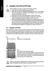
...extreme care when removing the CPU cooler. - 13 - To prevent such an occurrence, it is suggested that the CPU cooler can properly function to the CPU_FAN connector located on the surface of the CPU. Install all the CPU cooler components (Please refer to the CPU as a result of hardening... of the heat paste. Hardware Installation English 1-3-2 Installation of the CPU Cooler Fig.1 Before installing the CPU cooler, please first add an even layer of...
...extreme care when removing the CPU cooler. - 13 - To prevent such an occurrence, it is suggested that the CPU cooler can properly function to the CPU_FAN connector located on the surface of the CPU. Install all the CPU cooler components (Please refer to the CPU as a result of hardening... of the heat paste. Hardware Installation English 1-3-2 Installation of the CPU Cooler Fig.1 Before installing the CPU cooler, please first add an even layer of...

Manual
Page 15
... color. 3. DS/SS 4 memory modules DS/SS DS/SS DS/SS DDRII_4 - To enable Dual Channel mode with two memory modules (it is recommended to CPU limitation, if you must install them in DDRII_1 and DDRII_2 DIMM sockets. - 15 - DS/SS DS/SS If two memory modules are to achieve Dual... Side, "--": Empty) DIMM Socket DDRII_1 DDRII_2 DDRII_ 3 2 memory modules DS/SS DS/SS - - - - - - The following is installed. 2. Hardware Installation English Dual Channel Memory Configuration The GA-M61PM-S2 supports the Dual Channel Technology. Dual Channel mode will double.
... color. 3. DS/SS 4 memory modules DS/SS DS/SS DS/SS DDRII_4 - To enable Dual Channel mode with two memory modules (it is recommended to CPU limitation, if you must install them in DDRII_1 and DDRII_2 DIMM sockets. - 15 - DS/SS DS/SS If two memory modules are to achieve Dual... Side, "--": Empty) DIMM Socket DDRII_1 DDRII_2 DDRII_ 3 2 memory modules DS/SS DS/SS - - - - - - The following is installed. 2. Hardware Installation English Dual Channel Memory Configuration The GA-M61PM-S2 supports the Dual Channel Technology. Dual Channel mode will double.

Manual
Page 19
... can lead to handle the system voltage requirements. If you use of the power connector, the power supply can supply enough stable power to the CPU.
... can lead to handle the system voltage requirements. If you use of the power connector, the power supply can supply enough stable power to the CPU.
Manual
Page 20
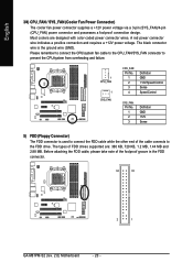
The types of the foolproof groove in the FDD connector. 34 33 2 1 GA-M61PM-S2 (rev. 2.0) Motherboard - 20 - Before attaching the FDD cable, please take note of FDD drives supported are designed with color-coded power connector wires...12V power voltage via a 3-pin (SYS_FAN)/4-pin (CPU_FAN) power connector and possesses a foolproof connection design. Please remember to connect the CPU/system fan cable to the CPU_FAN/SYS_FAN connector to prevent the CPU/system from overheating and failure. 1 CPU_FAN 1 SYS_FAN CPU_FAN: Pin No. 1 2 3 4 Definition GND +12V/Speed Control Sense ...
The types of the foolproof groove in the FDD connector. 34 33 2 1 GA-M61PM-S2 (rev. 2.0) Motherboard - 20 - Before attaching the FDD cable, please take note of FDD drives supported are designed with color-coded power connector wires...12V power voltage via a 3-pin (SYS_FAN)/4-pin (CPU_FAN) power connector and possesses a foolproof connection design. Please remember to connect the CPU/system fan cable to the CPU_FAN/SYS_FAN connector to prevent the CPU/system from overheating and failure. 1 CPU_FAN 1 SYS_FAN CPU_FAN: Pin No. 1 2 3 4 Definition GND +12V/Speed Control Sense ...

Manual
Page 33
... will stop for a disk error; it will not stop for a keyboard or disk error; Base Memory The POST of memory located above 1 MB in the CPU's memory address map. - 33 - Extended Memory The BIOS determines how much extended memory is detected during the POST. Hard drive information should be prompted. None...
... will stop for a disk error; it will not stop for a keyboard or disk error; Base Memory The POST of memory located above 1 MB in the CPU's memory address map. - 33 - Extended Memory The BIOS determines how much extended memory is detected during the POST. Hard drive information should be prompted. None...

Manual
Page 42
... at 80oC / 176oF. 90oC / 194oF Monitor System/CPU temperature at next boot. CPU Smart FAN Control(Note) Disabled Disable this function. (Default value) CPU/System FAN Fail Warning Disabled Disable CPU/system fan fail warning function. (Default value) Enabled Enable CPU/system fan fail warning function. GA-M61PM-S2 (rev. 2.0) Motherboard - 42 - If the case is closed, Case...
... at 80oC / 176oF. 90oC / 194oF Monitor System/CPU temperature at next boot. CPU Smart FAN Control(Note) Disabled Disable this function. (Default value) CPU/System FAN Fail Warning Disabled Disable CPU/system fan fail warning function. (Default value) Enabled Enable CPU/system fan fail warning function. GA-M61PM-S2 (rev. 2.0) Motherboard - 42 - If the case is closed, Case...

Manual
Page 43
...Mode This option is available only when CPU Smart FAN Control is enabled. BIOS Setup Auto BIOS autodetects the type of CPU fan you installed and sets the optimal CPU Smart FAN control mode for it. (Default value) Voltage Set to PWM when you use a CPU fan with a 3-pin fan power ...cable. PWM Set to Voltage when you use a CPU fan with a 4-pin fan power cable. 2-7 Load Fail-Safe Defaults CMOS Setup Utility-Copyright (C) 1984-2006 Award Software ` Standard CMOS ...
...Mode This option is available only when CPU Smart FAN Control is enabled. BIOS Setup Auto BIOS autodetects the type of CPU fan you installed and sets the optimal CPU Smart FAN control mode for it. (Default value) Voltage Set to PWM when you use a CPU fan with a 3-pin fan power ...cable. PWM Set to Voltage when you use a CPU fan with a 4-pin fan power cable. 2-7 Load Fail-Safe Defaults CMOS Setup Utility-Copyright (C) 1984-2006 Award Software ` Standard CMOS ...
Manual
Page 51
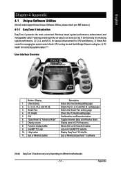
C.I.A./C.I.A.2 and M.I .B. "Easy Mode" & "Advance Mode" 7. GIGABYTE Logo 10. for special enhancement for CPU and Memory, 3) Smart-Fan control for managing fan speed control of CPU frequency Shows the current functions status Log on different motherboards. - 51 - Overclocking ...2. GO 6. Appendix Exit or Minimize button Description Enters the Overclocking setting page Enters the C.I.A./2 and M.I .B. 3. Featuring several powerful yet easy to GIGABYTE website Display ...
C.I.A./C.I.A.2 and M.I .B. "Easy Mode" & "Advance Mode" 7. GIGABYTE Logo 10. for special enhancement for CPU and Memory, 3) Smart-Fan control for managing fan speed control of CPU frequency Shows the current functions status Log on different motherboards. - 51 - Overclocking ...2. GO 6. Appendix Exit or Minimize button Description Enters the Overclocking setting page Enters the C.I.A./2 and M.I .B. 3. Featuring several powerful yet easy to GIGABYTE website Display ...


