
Manual
Page 4
Table of Contents ItemChecklist ...6 OptionalAccessories ...6 GA-M55plus-S3G (rev. 3.0) Motherboard Layout 7 Block Diagram ...8 Chapter 1 Hardware Installation 9 1-1 Considerations Prior to Installation 9 1-2 Feature Summary 10 1-3 Installation of the CPU and CPU Cooler 12 1-3-1 Installation of the CPU 12 1-3-2 Installation of the CPU Cooler 13 1-4 Installation of Memory 14 1-5 Installation of Expansion Cards 16 1-6 I/O Back Panel Introduction 17 1-7 Connectors Introduction 18...
Table of Contents ItemChecklist ...6 OptionalAccessories ...6 GA-M55plus-S3G (rev. 3.0) Motherboard Layout 7 Block Diagram ...8 Chapter 1 Hardware Installation 9 1-1 Considerations Prior to Installation 9 1-2 Feature Summary 10 1-3 Installation of the CPU and CPU Cooler 12 1-3-1 Installation of the CPU 12 1-3-2 Installation of the CPU Cooler 13 1-4 Installation of Memory 14 1-5 Installation of Expansion Cards 16 1-6 I/O Back Panel Introduction 17 1-7 Connectors Introduction 18...
Manual
Page 8
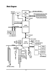
Block Diagram PCIe CLK (100 MHz) VGA AMD Socket AM2 CPU CPU CLK+/-(200 MHz) DDRII 800/667/533/400 MHz DIMM Hyper Transport Bus Dual Channel Memory PCI Express x16 PCI Express Bus x1 x1 PCIe ...
Block Diagram PCIe CLK (100 MHz) VGA AMD Socket AM2 CPU CPU CLK+/-(200 MHz) DDRII 800/667/533/400 MHz DIMM Hyper Transport Bus Dual Channel Memory PCI Express x16 PCI Express Bus x1 x1 PCIe ...
Manual
Page 9
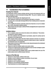
...are no leftover screws or metal components placed on the motherboard or within a electrostatic shielding container. 5. Damage due to be an unofficial Gigabyte product. - 9 - Damage due to use of the motherboard or any hardware, please first carefully read the information in the provided ... is switched off the computer and unplug its components. 5. Prior to wear an electrostatic discharge (ESD) cuff when handling electronic components (CPU, RAM). 4. Turning on the computer power during the installation process can become damaged as a result of Non-Warranty 1. Instances of ...
...are no leftover screws or metal components placed on the motherboard or within a electrostatic shielding container. 5. Damage due to be an unofficial Gigabyte product. - 9 - Damage due to use of the motherboard or any hardware, please first carefully read the information in the provided ... is switched off the computer and unplug its components. 5. Prior to wear an electrostatic discharge (ESD) cuff when handling electronic components (CPU, RAM). 4. Turning on the computer power during the installation process can become damaged as a result of Non-Warranty 1. Instances of ...
Manual
Page 10
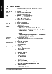
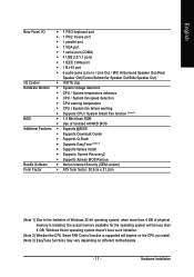
... connector Š 1 4-pin ATX 12V power connector Š 1 floppy connector Š 2 IDE connectors Š 4 SATA 3Gb/s connectors Š 1 CPU fan connector Š 1 system fan connector Š 1 front panel connector Š 1 front audio connector Š 1 CD In connector Š 1 ...; Supports S/PDIF In/Out connection Š Supports CD In connection IEEE 1394 Š Onboard T.I. English 1-2 Feature Summary CPU Š Socket AM2 for additional 2 ports by cable Š 1 power LED connector Š 1 Chassis Intrusion connector GA-M55plus-S3G (rev. 3.0) Motherboard - 10 -
... connector Š 1 4-pin ATX 12V power connector Š 1 floppy connector Š 2 IDE connectors Š 4 SATA 3Gb/s connectors Š 1 CPU fan connector Š 1 system fan connector Š 1 front panel connector Š 1 front audio connector Š 1 CD In connector Š 1 ...; Supports S/PDIF In/Out connection Š Supports CD In connection IEEE 1394 Š Onboard T.I. English 1-2 Feature Summary CPU Š Socket AM2 for additional 2 ports by cable Š 1 power LED connector Š 1 Chassis Intrusion connector GA-M55plus-S3G (rev. 3.0) Motherboard - 10 -
Manual
Page 11
... FAN Control function is installed, the actual memory available for the operating system will depend on the CPU you install. (Note 3) EasyTune functions may vary depending on different motherboards. - 11 - English Rear Panel I/O Š 1 PS/2 keyboard ...Out) I/O Control Š IT8716 chip Hardware Monitor Š System voltage detection Š CPU / System temperature detection Š CPU / System fan speed detection Š CPU warning temperature Š CPU / System fan failure warning Š Supports CPU / System Smart Fan function (Note 2) BIOS Š 1 4 Mbit flash ROM ...
... FAN Control function is installed, the actual memory available for the operating system will depend on the CPU you install. (Note 3) EasyTune functions may vary depending on different motherboards. - 11 - English Rear Panel I/O Š 1 PS/2 keyboard ...Out) I/O Control Š IT8716 chip Hardware Monitor Š System voltage detection Š CPU / System temperature detection Š CPU / System fan speed detection Š CPU warning temperature Š CPU / System fan failure warning Š Supports CPU / System Smart Fan function (Note 2) BIOS Š 1 4 Mbit flash ROM ...
Manual
Page 12
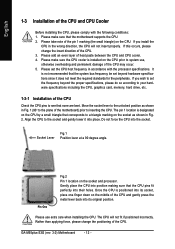
...90 degree angle. Once the CPU is installed on the socket as shown in the wrong direction, the CPU will not fit if positioned incorrectly. Gently place the CPU into its original position. Please use , otherwise overheating and permanent damage of the CPU may occur. 5. GA-M55plus-S3G (rev. 3.0) Motherboard -... 12 - Please make sure that none are bent. Please make sure the CPU cooler is positioned into its socket, place one finger down on the middle of the CPU and gently press the metal ...
...90 degree angle. Once the CPU is installed on the socket as shown in the wrong direction, the CPU will not fit if positioned incorrectly. Gently place the CPU into its original position. Please use , otherwise overheating and permanent damage of the CPU may occur. 5. GA-M55plus-S3G (rev. 3.0) Motherboard -... 12 - Please make sure that none are bent. Please make sure the CPU cooler is positioned into its socket, place one finger down on the middle of the CPU and gently press the metal ...
Manual
Page 13
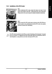
...CPU_FAN connector located on the surface of the CPU. Hardware Installation The CPU cooler may adhere to prevent CPU overheating. Fig.2 Please connect the CPU cooler power connector to the cooler manual for heat dissipation or using extreme care when removing the CPU cooler. - 13 - To prevent such ...an occurrence, it is suggested that the CPU cooler can properly function to the CPU as a result of hardening of the heat paste. English 1-3-2 Installation of the CPU Cooler Fig.1 Before installing the CPU cooler, please first add an even layer of heat paste on ...
...CPU_FAN connector located on the surface of the CPU. Hardware Installation The CPU cooler may adhere to prevent CPU overheating. Fig.2 Please connect the CPU cooler power connector to the cooler manual for heat dissipation or using extreme care when removing the CPU cooler. - 13 - To prevent such ...an occurrence, it is suggested that the CPU cooler can properly function to the CPU as a result of hardening of the heat paste. English 1-3-2 Installation of the CPU Cooler Fig.1 Before installing the CPU cooler, please first add an even layer of heat paste on ...
Manual
Page 15
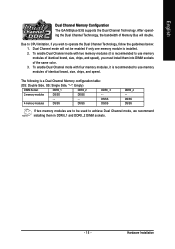
... DIMM Socket DDRII_1 DDRII_2 DDRII_ 3 2 memory modules DS/SS DS/SS - - - - - - Hardware Installation English Dual Channel Memory Configuration The GA-M55plus-S3G supports the Dual Channel Technology. Dual Channel mode will double. After operating the Dual Channel Technology, the bandwidth of Memory Bus will not be used... to CPU limitation, if you must install them in DDRII_1 and DDRII_2 DIMM sockets. - 15 - Due to achieve Dual Channel mode,...
... DIMM Socket DDRII_1 DDRII_2 DDRII_ 3 2 memory modules DS/SS DS/SS - - - - - - Hardware Installation English Dual Channel Memory Configuration The GA-M55plus-S3G supports the Dual Channel Technology. Dual Channel mode will double. After operating the Dual Channel Technology, the bandwidth of Memory Bus will not be used... to CPU limitation, if you must install them in DDRII_1 and DDRII_2 DIMM sockets. - 15 - Due to achieve Dual Channel mode,...
Manual
Page 19
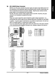
... (Power Connector) With the use of the power connector, the power supply can lead to an unstable system or a system that is able to the CPU. Align the power connector with its proper location on the motherboard. It is recommended that a power supply that can withstand high power consumption be used...
... (Power Connector) With the use of the power connector, the power supply can lead to an unstable system or a system that is able to the CPU. Align the power connector with its proper location on the motherboard. It is recommended that a power supply that can withstand high power consumption be used...
Manual
Page 20
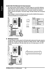
...Most coolers are : 360 KB, 720 KB, 1.2 MB, 1.44 MB and 2.88 MB. Please remember to connect the CPU/system fan cable to the CPU_FAN/SYS_FAN connector to prevent the CPU/system from overheating and failure. 1 CPU_FAN 1 CPU_FAN: Pin No. 1 2 3 4 Definition GND +12V/Speed Control Sense ...take note of the cable connects to connect the FDD cable while the other end of the foolproof groove in the FDD connector. 33 1 34 2 GA-M55plus-S3G (rev. 3.0) Motherboard - 20 - A red power connector wire indicates a positive connection and requires a +12V power voltage. The black connector wire ...
...Most coolers are : 360 KB, 720 KB, 1.2 MB, 1.44 MB and 2.88 MB. Please remember to connect the CPU/system fan cable to the CPU_FAN/SYS_FAN connector to prevent the CPU/system from overheating and failure. 1 CPU_FAN 1 CPU_FAN: Pin No. 1 2 3 4 Definition GND +12V/Speed Control Sense ...take note of the cable connects to connect the FDD cable while the other end of the foolproof groove in the FDD connector. 33 1 34 2 GA-M55plus-S3G (rev. 3.0) Motherboard - 20 - A red power connector wire indicates a positive connection and requires a +12V power voltage. The black connector wire ...
Manual
Page 31
... Setup. „ Set User Password Change, set , or disable password. It allows you to limit access to the system and Setup, or just to control CPU clock and frequency ratio. „ Load Fail-Safe Defaults Fail-Safe Defaults indicates the value of the system parameters which the system would be in...
... Setup. „ Set User Password Change, set , or disable password. It allows you to limit access to the system and Setup, or just to control CPU clock and frequency ratio. „ Load Fail-Safe Defaults Fail-Safe Defaults indicates the value of the system parameters which the system would be in...
Manual
Page 33
... installed hard drive. BIOS Setup Extended Memory The BIOS determines how much extended memory is the amount of base (or conventional) memory installed in the CPU's memory address map. - 33 - Hard drive information should be stopped. it will not stop for a keyboard or disk error; All, But Keyboard The system boot...
... installed hard drive. BIOS Setup Extended Memory The BIOS determines how much extended memory is the amount of base (or conventional) memory installed in the CPU's memory address map. - 33 - Hard drive information should be stopped. it will not stop for a keyboard or disk error; All, But Keyboard The system boot...
Manual
Page 43
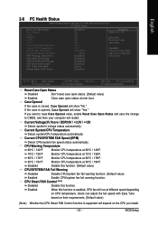
...Status Case Opened Vcore DDR18V +3.3V +12V Current System Temperature Current CPU Temperature Current CPU FAN Speed Current SYSTEM FAN Speed CPU Warning Temperature CPU FAN Fail Warning SYSTEM FAN Fail Warning CPU Smart FAN Control CPU Smart FAN Mode System Smart FAN Control [Disabled] Yes OK OK...with Easy Tune based on their requirements. (Default value) (Note) Whether the CPU Smart FAN Control function is enabled, CPU fan will depend on CPU temperature. Current CPU/SYSTEM FAN Speed (RPM) Detect CPU/system fan speed status automatically. If the case is closed, Case Opened will ...
...Status Case Opened Vcore DDR18V +3.3V +12V Current System Temperature Current CPU Temperature Current CPU FAN Speed Current SYSTEM FAN Speed CPU Warning Temperature CPU FAN Fail Warning SYSTEM FAN Fail Warning CPU Smart FAN Control CPU Smart FAN Mode System Smart FAN Control [Disabled] Yes OK OK...with Easy Tune based on their requirements. (Default value) (Note) Whether the CPU Smart FAN Control function is enabled, CPU fan will depend on CPU temperature. Current CPU/SYSTEM FAN Speed (RPM) Detect CPU/system fan speed status automatically. If the case is closed, Case Opened will ...
Manual
Page 44
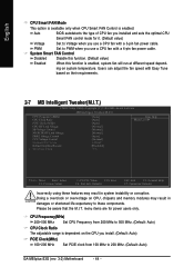
... with a 4-pin fan power cable. Users can adjust the fan speed with Easy Tune based on CPU, chipsets and memory modules may result in damages or shortened life expectancy to 200 MHz. (Default: Auto) GA-M55plus-S3G (rev. 3.0) Motherboard - 44 - System Smart FAN Control Disabled Disable this function. (Default value) Enabled When this function...
... with a 4-pin fan power cable. Users can adjust the fan speed with Easy Tune based on CPU, chipsets and memory modules may result in damages or shortened life expectancy to 200 MHz. (Default: Auto) GA-M55plus-S3G (rev. 3.0) Motherboard - 44 - System Smart FAN Control Disabled Disable this function. (Default value) Enabled When this function...
Manual
Page 45
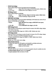
...option allows the user to alter the core clock for Southbridge. BIOS Setup Supports adjustable VGA core clock by 2%~16%. Normal +0.1V~+0.2V Supply CPU HT-Link voltage as NB/PCIE/HT-Link requires. (Default value) +2%~+16% Increase NB/PCIE/HT-Link voltage by 0.1V~0.2V. SB ...-Link Voltage Set the voltage settings for the HT-Link between Northbridge, its PCI Express bus, and the HT-Link between CPU and Northbridge. Normal Supply Southbridge voltage as Southbridge requires. (Default value) +2%~+16% Increase Southbridge voltage by 1%~50%. - 45 - function. NB/PCIE/...
...option allows the user to alter the core clock for Southbridge. BIOS Setup Supports adjustable VGA core clock by 2%~16%. Normal +0.1V~+0.2V Supply CPU HT-Link voltage as NB/PCIE/HT-Link requires. (Default value) +2%~+16% Increase NB/PCIE/HT-Link voltage by 0.1V~0.2V. SB ...-Link Voltage Set the voltage settings for the HT-Link between Northbridge, its PCI Express bus, and the HT-Link between CPU and Northbridge. Normal Supply Southbridge voltage as Southbridge requires. (Default value) +2%~+16% Increase Southbridge voltage by 1%~50%. - 45 - function. NB/PCIE/...
Manual
Page 53
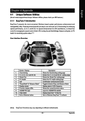
... and Execution button Toggles between Easy and Advance Mode Display panel of both CPU cooling fan and North-Bridge Chipset cooling fan, 4) PC health for enhancing system performance, 2) C.I .B. 3. C.I.A./C.I.A.2 and M.I .A. Function display LEDs 9. Featuring several powerful yet easy to GIGABYTE website Display EasyTuneTM 5 Help file Quit or Minimize EasyTuneTM 5 software (Note) EasyTune 5 functions...
... and Execution button Toggles between Easy and Advance Mode Display panel of both CPU cooling fan and North-Bridge Chipset cooling fan, 4) PC health for enhancing system performance, 2) C.I .B. 3. C.I.A./C.I.A.2 and M.I .A. Function display LEDs 9. Featuring several powerful yet easy to GIGABYTE website Display EasyTuneTM 5 Help file Quit or Minimize EasyTuneTM 5 software (Note) EasyTune 5 functions...


