Manual
Page 1
GA-M51GM-S2G AMD Socket AM2 Processor Motherboard User's Manual Rev. 1002 12ME-M51GMS2G-1002R * The WEEE marking on the product indicates this product must not be disposed of with user's other household waste and must be handed over to a designated collection point for the recycling of waste electrical and electronic equipment!! * The WEEE marking applies only in European Union's member states.
GA-M51GM-S2G AMD Socket AM2 Processor Motherboard User's Manual Rev. 1002 12ME-M51GMS2G-1002R * The WEEE marking on the product indicates this product must not be disposed of with user's other household waste and must be handed over to a designated collection point for the recycling of waste electrical and electronic equipment!! * The WEEE marking applies only in European Union's member states.
Manual
Page 4
Table of Contents ItemChecklist ...6 OptionalAccessories ...6 GA-M51GM-S2G Motherboard Layout 7 Block Diagram ...8 Chapter 1 Hardware Installation 9 1-1 Considerations Prior to Installation 9 1-2 Feature Summary 10 1-3 Installation of the CPU and CPU Cooler 12 1-3-1 Installation of the CPU ...
Table of Contents ItemChecklist ...6 OptionalAccessories ...6 GA-M51GM-S2G Motherboard Layout 7 Block Diagram ...8 Chapter 1 Hardware Installation 9 1-1 Considerations Prior to Installation 9 1-2 Feature Summary 10 1-3 Installation of the CPU and CPU Cooler 12 1-3-1 Installation of the CPU ...

Manual
Page 9
... recommended in the provided manual. 3. Damage due to be an unofficial Gigabyte product. - 9 - Damage due to use of electrostatic discharge (ESD). Please make sure there are connected. 4. English Chapter 1 Hardware Installation 1-1 Considerations Prior to Installation Preparing Your Computer The motherboard contains numerous delicate electronic circuits and components which can lead to damage...
... recommended in the provided manual. 3. Damage due to be an unofficial Gigabyte product. - 9 - Damage due to use of electrostatic discharge (ESD). Please make sure there are connected. 4. English Chapter 1 Hardware Installation 1-1 Considerations Prior to Installation Preparing Your Computer The motherboard contains numerous delicate electronic circuits and components which can lead to damage...
Manual
Page 10
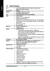
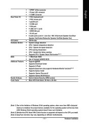
...; Supports High Definition Audio Š Supports Line In ; Line Out (Front Speaker Out) ; English 1-2 Feature Summary CPU Š Socket AM2 for additional 2 port by cable GA-M51GM-S2G Motherboard - 10 - Center/Subwoofer Speaker Out ; Surround Speaker Out (Rear Speaker Out) ;
...; Supports High Definition Audio Š Supports Line In ; Line Out (Front Speaker Out) ; English 1-2 Feature Summary CPU Š Socket AM2 for additional 2 port by cable GA-M51GM-S2G Motherboard - 10 - Center/Subwoofer Speaker Out ; Surround Speaker Out (Rear Speaker Out) ;
Manual
Page 11
... is installed, the actual memory available for the operating system will depend on the CPU you install. (Note 3) EasyTune functions may vary depending on different motherboards. - 11 - English Š 1 SPDIF In/Out connector Š 1 Power LED connector Š 1 COMB connector Rear Panel I/O Š 1 PS/2 keyboard port Š 1 PS/2 mouse port Š...
... is installed, the actual memory available for the operating system will depend on the CPU you install. (Note 3) EasyTune functions may vary depending on different motherboards. - 11 - English Š 1 SPDIF In/Out connector Š 1 Power LED connector Š 1 COMB connector Rear Panel I/O Š 1 PS/2 keyboard port Š 1 PS/2 mouse port Š...
Manual
Page 12
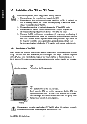
... prior to inserting the CPU. Pin One Please use , otherwise overheating and permanent damage of the CPU Check the CPU pins to see that the motherboard supports the CPU. 2. Please add an even layer of the CPU. Fig.2 Pin 1 location on the middle of the CPU and CPU Cooler... heat paste between the CPU and CPU cooler. 4. Gently place the CPU into position making sure that corresponds to a triangle marking on the CPU. GA-M51GM-S2G Motherboard - 12 - Move the socket lever to the socket and gently lower it does not meet the required standards for the peripherals. The pin 1 location...
... prior to inserting the CPU. Pin One Please use , otherwise overheating and permanent damage of the CPU Check the CPU pins to see that the motherboard supports the CPU. 2. Please add an even layer of the CPU. Fig.2 Pin 1 location on the middle of the CPU and CPU Cooler... heat paste between the CPU and CPU cooler. 4. Gently place the CPU into position making sure that corresponds to a triangle marking on the CPU. GA-M51GM-S2G Motherboard - 12 - Move the socket lever to the socket and gently lower it does not meet the required standards for the peripherals. The pin 1 location...

Manual
Page 13
... the CPU. English 1-3-2 Installation of the CPU cooler Fig.1 Before installing the CPU cooler, please first add an even layer of heat paste on the motherboard so that either thermal tape rather than heat paste be used for detailed installation instructions). Fig.2 Please connect the CPU cooler power connector to the...
... the CPU. English 1-3-2 Installation of the CPU cooler Fig.1 Before installing the CPU cooler, please first add an even layer of heat paste on the motherboard so that either thermal tape rather than heat paste be used for detailed installation instructions). Fig.2 Please connect the CPU cooler power connector to the...
Manual
Page 14
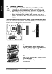
... so the DIMM memory module can be installed in only one direction. It is recommended that the computer power is supported by the motherboard. The memory capacity used is switched off to lock the DIMM module. English 1-4 Installation of Memory Before installing the memory modules, .... Please make sure that memory of the DIMM sockets to prevent hardware damage. 3. Memory modules are unable to remove the DIMM module. GA-M51GM-S2G Motherboard - 14 - If you wish to insert the module, please switch the direction. Fig.2 Close the plastic clip at both edges of similar...
... so the DIMM memory module can be installed in only one direction. It is recommended that the computer power is supported by the motherboard. The memory capacity used is switched off to lock the DIMM module. English 1-4 Installation of Memory Before installing the memory modules, .... Please make sure that memory of the DIMM sockets to prevent hardware damage. 3. Memory modules are unable to remove the DIMM module. GA-M51GM-S2G Motherboard - 14 - If you wish to insert the module, please switch the direction. Fig.2 Close the plastic clip at both edges of similar...
Manual
Page 16
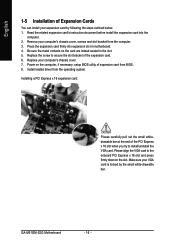
... the small whitedrawable bar at the end of the PCI Express x 16 slot when you try to secure the slot bracket of the expansion card. 6. GA-M51GM-S2G Motherboard - 16 - English 1-5 Installation of Expansion Cards You can install your computer's chassis cover, screws and slot bracket from the operating system. Read the related expansion...'s instruction document before install the expansion card into expansion slot in the slot. 5. Be sure the metal contacts on the card are indeed seated in motherboard. 4. Install related driver from the computer. 3.
... the small whitedrawable bar at the end of the PCI Express x 16 slot when you try to secure the slot bracket of the expansion card. 6. GA-M51GM-S2G Motherboard - 16 - English 1-5 Installation of Expansion Cards You can install your computer's chassis cover, screws and slot bracket from the operating system. Read the related expansion...'s instruction document before install the expansion card into expansion slot in the slot. 5. Be sure the metal contacts on the card are indeed seated in motherboard. 4. Install related driver from the computer. 3.
Manual
Page 18
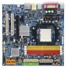
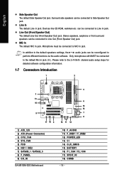
... information. 1-7 Connectors Introduction 1 2 5 3 13 6 10 15 14 9 7 8 17 18 4 16 11 12 1) ATX_12V 2) ATX (Power Connector) 3) CPU_FAN 4) SYS_FAN 5) FDD 6) IDE1 / IDE2 7) SATAII0_1 / SATAII2_3 8) F_PANEL 9) CD_IN GA-M51GM-S2G Motherboard 10) F_AUDIO 11) F_USB1 / F_USB2 12) POWER_LED 13) CI 14) CLR_CMOS 15) BATTERY 16) F1_1394 / F2_1394 17) SPDIF_IO 18) COMB - 18 - English Side Speaker Out...
... information. 1-7 Connectors Introduction 1 2 5 3 13 6 10 15 14 9 7 8 17 18 4 16 11 12 1) ATX_12V 2) ATX (Power Connector) 3) CPU_FAN 4) SYS_FAN 5) FDD 6) IDE1 / IDE2 7) SATAII0_1 / SATAII2_3 8) F_PANEL 9) CD_IN GA-M51GM-S2G Motherboard 10) F_AUDIO 11) F_USB1 / F_USB2 12) POWER_LED 13) CI 14) CLR_CMOS 15) BATTERY 16) F1_1394 / F2_1394 17) SPDIF_IO 18) COMB - 18 - English Side Speaker Out...

Manual
Page 19
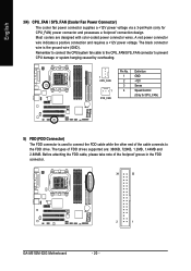
... is able to the CPU. If you use a 24-pin ATX power supply, please remove the small cover on the power connector on the motherboard and connect tightly. Definition 2 1 1 GND 4 3 2 GND 3 +12V 4 +12V Pin No. Align the power connector with its proper location on the... plugging in the power cord ; Please use a power supply that is recommended that a power supply that all the components on the motherboard. It is unable to all components and devices are properly installed. English 1/2) ATX_12V / ATX (Power Connector) With the use of the power connector, the power...
... is able to the CPU. If you use a 24-pin ATX power supply, please remove the small cover on the power connector on the motherboard and connect tightly. Definition 2 1 1 GND 4 3 2 GND 3 +12V 4 +12V Pin No. Align the power connector with its proper location on the... plugging in the power cord ; Please use a power supply that is recommended that a power supply that all the components on the motherboard. It is unable to all components and devices are properly installed. English 1/2) ATX_12V / ATX (Power Connector) With the use of the power connector, the power...
Manual
Page 20
... drive. A red power connector wire indicates a positive connection and requires a +12V power voltage. The types of the foolproof groove in the FDD connector. 34 33 2 1 GA-M51GM-S2G Motherboard - 20 - Before attaching the FDD cable, please take note of FDD drives supported are designed with color-coded power connector wires. English 3/4) CPU_FAN / SYS_FAN (Cooler...
... drive. A red power connector wire indicates a positive connection and requires a +12V power voltage. The types of the foolproof groove in the FDD connector. 34 33 2 1 GA-M51GM-S2G Motherboard - 20 - Before attaching the FDD cable, please take note of FDD drives supported are designed with color-coded power connector wires. English 3/4) CPU_FAN / SYS_FAN (Cooler...
Manual
Page 22
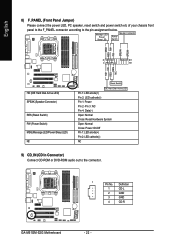
... 2: LED cathode(-) NC 9) CD_IN (CD In Connector) Connect CD-ROM or DVD-ROM audio out to the pin assignment below. Definition 1 CD-L 2 GND 3 GND 4 CD-R GA-M51GM-S2G Motherboard - 22 -
... 2: LED cathode(-) NC 9) CD_IN (CD In Connector) Connect CD-ROM or DVD-ROM audio out to the pin assignment below. Definition 1 CD-L 2 GND 3 GND 4 CD-R GA-M51GM-S2G Motherboard - 22 -
Manual
Page 24
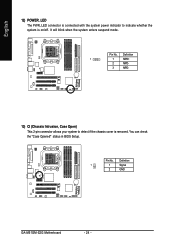
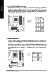
Definition 1 1 MPD+ 2 MPD- 3 MPD- 13) CI (Chassis Intrusion, Case Open) This 2-pin connector allows your system to indicate whether the system is removed. English 12) POWER_LED The PWR_LED connector is connected with the system power indicator to detect if the chassis cover is on/off. Pin No. You can check the "Case Opened" status in BIOS Setup. Definition 1 1 Signal 2 GND GA-M51GM-S2G Motherboard - 24 - Pin No. It will blink when the system enters suspend mode.
Definition 1 1 MPD+ 2 MPD- 3 MPD- 13) CI (Chassis Intrusion, Case Open) This 2-pin connector allows your system to indicate whether the system is removed. English 12) POWER_LED The PWR_LED connector is connected with the system power indicator to detect if the chassis cover is on/off. Pin No. You can check the "Case Opened" status in BIOS Setup. Definition 1 1 Signal 2 GND GA-M51GM-S2G Motherboard - 24 - Pin No. It will blink when the system enters suspend mode.
Manual
Page 26
... connection between the cable and connector will make the device unable to work or even damage it . Definition 5 1 6 2 1 Power 2 No Pin 3 SPDIF 4 SPDIFI 5 GND 6 GND GA-M51GM-S2G Motherboard - 26 - Check the pin assignment carefully while you connect the SPDIF cable, incorrect connection between the cable and connector will make the device unable to...
... connection between the cable and connector will make the device unable to work or even damage it . Definition 5 1 6 2 1 Power 2 No Pin 3 SPDIF 4 SPDIFI 5 GND 6 GND GA-M51GM-S2G Motherboard - 26 - Check the pin assignment carefully while you connect the SPDIF cable, incorrect connection between the cable and connector will make the device unable to...
Manual
Page 29
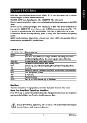
... operation that may result in the CMOS SRAM of the screen. When the power is turned off, the battery on the motherboard supplies the necessary power to a new BIOS, either GIGABYTE's Q-Flash or @BIOS utility can enter the BIOS setup screen by pressing "Ctrl + F1". To exit the Help Window press .... and the possible selections for Main Menu Main Menu The on-line description of the highlighted setup function is displayed at the bottom of the motherboard. Status Page Setup Menu / Option Page Setup Menu Press to pop up a small help , only for Status Page Setup Menu and Option Page Setup...
... operation that may result in the CMOS SRAM of the screen. When the power is turned off, the battery on the motherboard supplies the necessary power to a new BIOS, either GIGABYTE's Q-Flash or @BIOS utility can enter the BIOS setup screen by pressing "Ctrl + F1". To exit the Help Window press .... and the possible selections for Main Menu Main Menu The on-line description of the highlighted setup function is displayed at the bottom of the motherboard. Status Page Setup Menu / Option Page Setup Menu Press to pop up a small help , only for Status Page Setup Menu and Option Page Setup...
Manual
Page 30
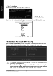
The BIOS Setup menus described in the BIOS when somehow the system works not stable as figure below) will appear on cards) device. GA-M51GM-S2G E17 . . . . :BIOS Setup/Q-Flash, : XpressRecovery2, For Boot Menu 04/03/2006-C51-MCP51-6A61HG0GC-00 For Boot Menu Use < > or < > to select a...option hidden.Please Load Optimized Defaults in this menu. This action makes the system reset to the default for onboard (or add-on the screen. GA-M51GM-S2G Motherboard - 30 - Boot Menu == Select a Boot First device == Floppy LS120 Hard Disk CDROM ZIP USB-FDD USB-ZIP USB-CDROM USB-HDD Legacy...
The BIOS Setup menus described in the BIOS when somehow the system works not stable as figure below) will appear on cards) device. GA-M51GM-S2G E17 . . . . :BIOS Setup/Q-Flash, : XpressRecovery2, For Boot Menu 04/03/2006-C51-MCP51-6A61HG0GC-00 For Boot Menu Use < > or < > to select a...option hidden.Please Load Optimized Defaults in this menu. This action makes the system reset to the default for onboard (or add-on the screen. GA-M51GM-S2G Motherboard - 30 - Boot Menu == Select a Boot First device == Floppy LS120 Hard Disk CDROM ZIP USB-FDD USB-ZIP USB-CDROM USB-HDD Legacy...
Manual
Page 32
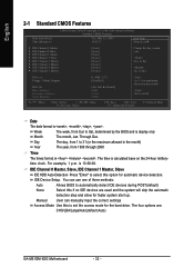
... clock. For example, 1 p.m. You can manually input the correct settings Access Mode Use this if no IDE devices are : CHS/LBA/Large/Auto(default:Auto) GA-M51GM-S2G Motherboard - 32 - Manual User can use one of three methods: Auto Allows BIOS to automatically detect IDE devices during POST(default) None Select this to 2098...
... clock. For example, 1 p.m. You can manually input the correct settings Access Mode Use this if no IDE devices are : CHS/LBA/Large/Auto(default:Auto) GA-M51GM-S2G Motherboard - 32 - Manual User can use one of three methods: Auto Allows BIOS to automatically detect IDE devices during POST(default) None Select this to 2098...
Manual
Page 34
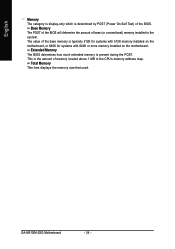
...base (or conventional) memory installed in the CPU's memory address map. This is determined by POST (Power On Self Test) of the BIOS. GA-M51GM-S2G Motherboard - 34 - Extended Memory The BIOS determines how much extended memory is typically 512K for systems with 512K memory installed on the... motherboard, or 640K for systems with 640K or more memory installed on the motherboard. The value of the base memory is present during the POST. Total Memory This item displays the ...
...base (or conventional) memory installed in the CPU's memory address map. This is determined by POST (Power On Self Test) of the BIOS. GA-M51GM-S2G Motherboard - 34 - Extended Memory The BIOS determines how much extended memory is typically 512K for systems with 512K memory installed on the... motherboard, or 640K for systems with 640K or more memory installed on the motherboard. The value of the base memory is present during the POST. Total Memory This item displays the ...
Manual
Page 36
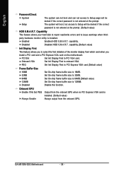
... Display First to 128MB. Onboard GPU Enable If No Ext PEG Output from the onboard GPU when no PCI Express VGA card is installed. GA-M51GM-S2G Motherboard - 36 - capability.(Default value) Init Display First This feature allows you install a PCI card and a PCI Express VGA card on the... motherboard. Disabled Disabled HDD S.M.A.R.T. PEG Set Init Display First to PCI Express VGA card.(Default value) Frame Buffer Size 16MB 32MB Set On-chip frame ...
... Display First to 128MB. Onboard GPU Enable If No Ext PEG Output from the onboard GPU when no PCI Express VGA card is installed. GA-M51GM-S2G Motherboard - 36 - capability.(Default value) Init Display First This feature allows you install a PCI card and a PCI Express VGA card on the... motherboard. Disabled Disabled HDD S.M.A.R.T. PEG Set Init Display First to PCI Express VGA card.(Default value) Frame Buffer Size 16MB 32MB Set On-chip frame ...


