Manual
Page 4
Table of Contents ItemChecklist ...6 OptionalAccessories ...6 GA-M51GM-S2G Motherboard Layout 7 Block Diagram ...8 Chapter 1 Hardware Installation 9 1-1 Considerations Prior to Installation 9 1-2 Feature Summary 10 1-3 Installation of the CPU and CPU Cooler 12 1-3-1 Installation of the CPU 12 1-3-2 Installation of the CPU cooler 13 1-4 Installation of Memory 14 1-5 Installation of Expansion Cards 16 1-6 I/O Back Panel Introduction 17 1-7 Connectors Introduction 18 Chapter 2 BIOS...
Table of Contents ItemChecklist ...6 OptionalAccessories ...6 GA-M51GM-S2G Motherboard Layout 7 Block Diagram ...8 Chapter 1 Hardware Installation 9 1-1 Considerations Prior to Installation 9 1-2 Feature Summary 10 1-3 Installation of the CPU and CPU Cooler 12 1-3-1 Installation of the CPU 12 1-3-2 Installation of the CPU cooler 13 1-4 Installation of Memory 14 1-5 Installation of Expansion Cards 16 1-6 I/O Back Panel Introduction 17 1-7 Connectors Introduction 18 Chapter 2 BIOS...

Manual
Page 9
... connected. 4. Damage as a result of uncertified components. 5. Damage due to use of the motherboard or any metal leads or connectors. 3. Prior to the installation of the product, please consult ...CPU, RAM). 4. Turning on top of Non-Warranty 1. Thus, prior to natural disaster, accident or human cause. 2. Damage due to be an unofficial Gigabyte product. - 9 - Product determined to improper installation. 4. If you are required for warranty validation. 2. English Chapter 1 Hardware Installation 1-1 Considerations Prior to Installation Preparing Your Computer The motherboard...
... connected. 4. Damage as a result of uncertified components. 5. Damage due to use of the motherboard or any metal leads or connectors. 3. Prior to the installation of the product, please consult ...CPU, RAM). 4. Turning on top of Non-Warranty 1. Thus, prior to natural disaster, accident or human cause. 2. Damage due to be an unofficial Gigabyte product. - 9 - Product determined to improper installation. 4. If you are required for warranty validation. 2. English Chapter 1 Hardware Installation 1-1 Considerations Prior to Installation Preparing Your Computer The motherboard...
Manual
Page 10
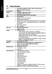
...; 1 front panel connector Š 1 front audio connector Š 1 CD In connector Š 2 USB 2.0/1.1 connectors for additional 4 USB 2.0/1.1 ports by cable GA-M51GM-S2G Motherboard - 10 - Surround Speaker Out (Rear Speaker Out) ; English 1-2 Feature Summary CPU Š Socket AM2 for additional 2 port by cables Š 2 IEEE1394a connectors for AMD AthlonTM 64 FX / AthlonTM 64 X2 Dual...
...; 1 front panel connector Š 1 front audio connector Š 1 CD In connector Š 2 USB 2.0/1.1 connectors for additional 4 USB 2.0/1.1 ports by cable GA-M51GM-S2G Motherboard - 10 - Surround Speaker Out (Rear Speaker Out) ; English 1-2 Feature Summary CPU Š Socket AM2 for additional 2 port by cables Š 2 IEEE1394a connectors for AMD AthlonTM 64 FX / AthlonTM 64 X2 Dual...
Manual
Page 11
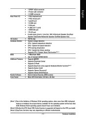
...Control Š IT8716 chip Hardware Monitor Š System voltage detection Š CPU / System temperature detection Š CPU / System fan speed detection Š CPU warning temperature Š CPU / System fan failure warning Š Supports CPU / System Smart Fan function(Note 2) BIOS Š 1 4Mbit flash ROM...the operating system will depend on the CPU you install. (Note 3) EasyTune functions may vary depending on different motherboards. - 11 - Windows 64-bit operating system doesn't have such limitation. (Note 2) Whether the CPU Smart FAN Control function is supported will...
...Control Š IT8716 chip Hardware Monitor Š System voltage detection Š CPU / System temperature detection Š CPU / System fan speed detection Š CPU warning temperature Š CPU / System fan failure warning Š Supports CPU / System Smart Fan function(Note 2) BIOS Š 1 4Mbit flash ROM...the operating system will depend on the CPU you install. (Note 3) EasyTune functions may vary depending on different motherboards. - 11 - Windows 64-bit operating system doesn't have such limitation. (Note 2) Whether the CPU Smart FAN Control function is supported will...
Manual
Page 12
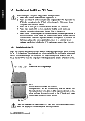
... One Please use , otherwise overheating and permanent damage of the CPU may occur. 5. Rather than applying force, please change the insert direction of the CPU. 3. Please make sure that the motherboard supports the CPU. 2. GA-M51GM-S2G Motherboard - 12 - Please set the CPU host frequency in Fig. 2. Socket Lever Fig.1 Position lever at a 90 degree angle. Please add an...
... One Please use , otherwise overheating and permanent damage of the CPU may occur. 5. Rather than applying force, please change the insert direction of the CPU. 3. Please make sure that the motherboard supports the CPU. 2. GA-M51GM-S2G Motherboard - 12 - Please set the CPU host frequency in Fig. 2. Socket Lever Fig.1 Position lever at a 90 degree angle. Please add an...

Manual
Page 13
...of the heat paste. The CPU cooler may adhere to prevent CPU overheating. To prevent such an occurrence, it is suggested that the CPU cooler can properly function to the CPU as a result of hardening of the CPU. Hardware Installation Fig.2 Please connect the CPU cooler power connector to the... for heat dissipation or using extreme care when removing the CPU cooler. - 13 - English 1-3-2 Installation of the CPU cooler Fig.1 Before installing the CPU cooler, please first add an even layer of heat paste on the motherboard so that either thermal tape rather than heat paste be ...
...of the heat paste. The CPU cooler may adhere to prevent CPU overheating. To prevent such an occurrence, it is suggested that the CPU cooler can properly function to the CPU as a result of hardening of the CPU. Hardware Installation Fig.2 Please connect the CPU cooler power connector to the... for heat dissipation or using extreme care when removing the CPU cooler. - 13 - English 1-3-2 Installation of the CPU cooler Fig.1 Before installing the CPU cooler, please first add an even layer of heat paste on the motherboard so that either thermal tape rather than heat paste be ...

Manual
Page 19
...GND - 19 - Hardware Installation Align the power connector with its proper location on the motherboard and connect tightly. Please use a power supply that all the components on the motherboard. Before connecting the power connector, please make sure that is not connected, the system... will not start . If the ATX_12V power connector is able to the CPU. Otherwise, please do not remove it. Pin No. Definition 2...
...GND - 19 - Hardware Installation Align the power connector with its proper location on the motherboard and connect tightly. Please use a power supply that all the components on the motherboard. Before connecting the power connector, please make sure that is not connected, the system... will not start . If the ATX_12V power connector is able to the CPU. Otherwise, please do not remove it. Pin No. Definition 2...
Manual
Page 20
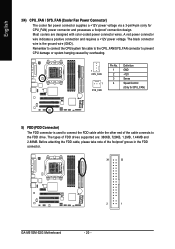
...2MB, 1.44MB and 2.88MB. A red power connector wire indicates a positive connection and requires a +12V power voltage. Remember to connect the CPU/system fan cable to the CPU_FAN/SYS_FAN connector to the FDD drive. English 3/4) CPU_FAN / SYS_FAN (Cooler Fan Power Connector) The cooler fan ...The types of the foolproof groove in the FDD connector. 34 33 2 1 GA-M51GM-S2G Motherboard - 20 - The black connector wire is used to connect the FDD cable while the other end of the cable connects to prevent CPU damage or system hanging caused by overheating. 1 CPU_FAN 1 SYS_FAN Pin No. ...
...2MB, 1.44MB and 2.88MB. A red power connector wire indicates a positive connection and requires a +12V power voltage. Remember to connect the CPU/system fan cable to the CPU_FAN/SYS_FAN connector to the FDD drive. English 3/4) CPU_FAN / SYS_FAN (Cooler Fan Power Connector) The cooler fan ...The types of the foolproof groove in the FDD connector. 34 33 2 1 GA-M51GM-S2G Motherboard - 20 - The black connector wire is used to connect the FDD cable while the other end of the cable connects to prevent CPU damage or system hanging caused by overheating. 1 CPU_FAN 1 SYS_FAN Pin No. ...
Manual
Page 34
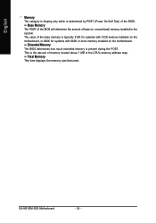
... category is display-only which is the amount of memory located above 1 MB in the system. GA-M51GM-S2G Motherboard - 34 - This is determined by POST (Power On Self Test) of base (or conventional) memory installed in the CPU's memory address map. Base Memory The POST of the BIOS will determine the amount of the...
... category is display-only which is the amount of memory located above 1 MB in the system. GA-M51GM-S2G Motherboard - 34 - This is determined by POST (Power On Self Test) of base (or conventional) memory installed in the CPU's memory address map. Base Memory The POST of the BIOS will determine the amount of the...
Manual
Page 44
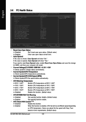
... Speed (RPM) Detect system/CPU fan speed status automatically. If the case is closed, Case Opened will show "No." Monitor CPU temperature at next boot. Case Opened If the case is opened, Case Opened will show "Yes." Monitor CPU temperature at different speed depending on their requirements. (Default value) GA-M51GM-S2G Motherboard - 44 - Enabled When this...
... Speed (RPM) Detect system/CPU fan speed status automatically. If the case is closed, Case Opened will show "No." Monitor CPU temperature at next boot. Case Opened If the case is opened, Case Opened will show "Yes." Monitor CPU temperature at different speed depending on their requirements. (Default value) GA-M51GM-S2G Motherboard - 44 - Enabled When this...

Manual
Page 53
C.I.A./C.I.A.2 and M.I .A. Display screen Display panel of both CPU cooling fan and North-Bridge Chipset cooling fan, 4) PC health for monitoring system status.(Note) User Interface Overview Button / Display Description 1. GIGABYTE Logo Log on different motherboards. - 53 - English Chapter 4 Appendix 4-1 Unique Software Utilities 4-1-1 EasyTune 5 Introduction EasyTune 5 presents the most convenient Windows based system performance enhancement...
C.I.A./C.I.A.2 and M.I .A. Display screen Display panel of both CPU cooling fan and North-Bridge Chipset cooling fan, 4) PC health for monitoring system status.(Note) User Interface Overview Button / Display Description 1. GIGABYTE Logo Log on different motherboards. - 53 - English Chapter 4 Appendix 4-1 Unique Software Utilities 4-1-1 EasyTune 5 Introduction EasyTune 5 presents the most convenient Windows based system performance enhancement...
Manual
Page 68
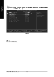
...-2005 Award Software Advanced BIOS Features Hard Disk Boot Priority First Boot Device Second Boot Device Third Boot Device Password Check # CPU Hyper-Threading Limit CPUID Max. to CD-ROM (Figure 5). GA-M51GM-S2G Motherboard - 68 - English Step 3: To boot from Windows installation CD-ROM, set First Boot Device under the Advanced BIOS Features menu...
...-2005 Award Software Advanced BIOS Features Hard Disk Boot Priority First Boot Device Second Boot Device Third Boot Device Password Check # CPU Hyper-Threading Limit CPUID Max. to CD-ROM (Figure 5). GA-M51GM-S2G Motherboard - 68 - English Step 3: To boot from Windows installation CD-ROM, set First Boot Device under the Advanced BIOS Features menu...


