Manual
Page 1
GA-M51GM-S2G AMD Socket AM2 Processor Motherboard User's Manual Rev. 1002 12ME-M51GMS2G-1002R * The WEEE marking on the product indicates this product must not be disposed of with user's other household waste and must be handed over to a designated collection point for the recycling of waste electrical and electronic equipment!! * The WEEE marking applies only in European Union's member states.
GA-M51GM-S2G AMD Socket AM2 Processor Motherboard User's Manual Rev. 1002 12ME-M51GMS2G-1002R * The WEEE marking on the product indicates this product must not be disposed of with user's other household waste and must be handed over to a designated collection point for the recycling of waste electrical and electronic equipment!! * The WEEE marking applies only in European Union's member states.
Manual
Page 4
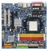
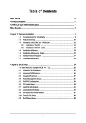
Table of Contents ItemChecklist ...6 OptionalAccessories ...6 GA-M51GM-S2G Motherboard Layout 7 Block Diagram ...8 Chapter 1 Hardware Installation 9 1-1 Considerations Prior to Installation 9 1-2 Feature Summary 10 1-3 Installation of the CPU and CPU Cooler 12 1-3-1 Installation of the CPU ...
Table of Contents ItemChecklist ...6 OptionalAccessories ...6 GA-M51GM-S2G Motherboard Layout 7 Block Diagram ...8 Chapter 1 Hardware Installation 9 1-1 Considerations Prior to Installation 9 1-2 Feature Summary 10 1-3 Installation of the CPU and CPU Cooler 12 1-3-1 Installation of the CPU ...

Manual
Page 9
...due to use of violating the conditions recommended in contact with the motherboard circuit or its power cord. 2. Product determined to installation, please follow the instructions below: 1. Thus, prior to be an unofficial Gigabyte product. - 9 - Prior to installing the electronic components, please ...for warranty validation. 2. Damage due to natural disaster, accident or human cause. 2. Damage due to use of the motherboard or any metal leads or connectors. 3. Damage due to improper installation. 4. English Chapter 1 Hardware Installation 1-1 Considerations Prior to Installation...
...due to use of violating the conditions recommended in contact with the motherboard circuit or its power cord. 2. Product determined to installation, please follow the instructions below: 1. Thus, prior to be an unofficial Gigabyte product. - 9 - Prior to installing the electronic components, please ...for warranty validation. 2. Damage due to natural disaster, accident or human cause. 2. Damage due to use of the motherboard or any metal leads or connectors. 3. Damage due to improper installation. 4. English Chapter 1 Hardware Installation 1-1 Considerations Prior to Installation...
Manual
Page 10
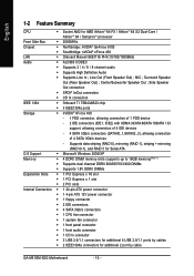
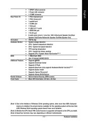
... Š 1 system fan connector Š 1 front panel connector Š 1 front audio connector Š 1 CD In connector Š 2 USB 2.0/1.1 connectors for additional 4 USB 2.0/1.1 ports by cable GA-M51GM-S2G Motherboard - 10 - Center/Subwoofer Speaker Out ; Side Speaker Out connection Š SPDIF In/Out connection Š CD In connection IEEE 1394 Š Onboard TI TSB43AB23 chip...
... Š 1 system fan connector Š 1 front panel connector Š 1 front audio connector Š 1 CD In connector Š 2 USB 2.0/1.1 connectors for additional 4 USB 2.0/1.1 ports by cable GA-M51GM-S2G Motherboard - 10 - Center/Subwoofer Speaker Out ; Side Speaker Out connection Š SPDIF In/Out connection Š CD In connection IEEE 1394 Š Onboard TI TSB43AB23 chip...
Manual
Page 11
... is installed, the actual memory available for the operating system will depend on the CPU you install. (Note 3) EasyTune functions may vary depending on different motherboards. - 11 - Hardware Installation
... is installed, the actual memory available for the operating system will depend on the CPU you install. (Note 3) EasyTune functions may vary depending on different motherboards. - 11 - Hardware Installation
Manual
Page 12
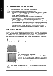
...not force the CPU into place. Please make sure the CPU cooler is not recommended that the motherboard supports the CPU. 2. Gently place the CPU into their holes. The CPU will not insert properly. GA-M51GM-S2G Motherboard - 12 - Please take note of the pin 1 marking (the small triangle) on the ... CPU and CPU cooler. 4. Move the socket lever to the unlocked position as shown in Fig. 1 (90o to the plane of the motherboard) prior to see that the CPU pins fitperfectly into position making sure that none are bent. English 1-3 Installation of the CPU and CPU Cooler...
...not force the CPU into place. Please make sure the CPU cooler is not recommended that the motherboard supports the CPU. 2. Gently place the CPU into their holes. The CPU will not insert properly. GA-M51GM-S2G Motherboard - 12 - Please take note of the pin 1 marking (the small triangle) on the ... CPU and CPU cooler. 4. Move the socket lever to the unlocked position as shown in Fig. 1 (90o to the plane of the motherboard) prior to see that the CPU pins fitperfectly into position making sure that none are bent. English 1-3 Installation of the CPU and CPU Cooler...

Manual
Page 13
... - Hardware Installation English 1-3-2 Installation of the CPU cooler Fig.1 Before installing the CPU cooler, please first add an even layer of heat paste on the motherboard so that either thermal tape rather than heat paste be used for detailed installation instructions). Install all the CPU cooler components (Please refer to prevent...
... - Hardware Installation English 1-3-2 Installation of the CPU cooler Fig.1 Before installing the CPU cooler, please first add an even layer of heat paste on the motherboard so that either thermal tape rather than heat paste be used for detailed installation instructions). Install all the CPU cooler components (Please refer to prevent...
Manual
Page 14
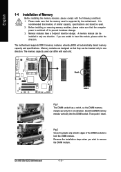
... fit in only one direction. The memory capacity used can be used is supported by the motherboard. Then push it down. GA-M51GM-S2G Motherboard - 14 - Before installing or removing memory modules, please make sure that the memory used . 2. The motherboard supports DDR II memory modules, whereby BIOS will automatically detect memory capacity and specifications. Notch...
... fit in only one direction. The memory capacity used can be used is supported by the motherboard. Then push it down. GA-M51GM-S2G Motherboard - 14 - Before installing or removing memory modules, please make sure that the memory used . 2. The motherboard supports DDR II memory modules, whereby BIOS will automatically detect memory capacity and specifications. Notch...
Manual
Page 16
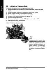
... install/uninstall the VGA card. Press the expansion card firmly into the computer. 2. Be sure the metal contacts on the card are indeed seated in motherboard. 4. GA-M51GM-S2G Motherboard - 16 - Read the related expansion card's instruction document before install the expansion card into expansion slot in the slot. 5. English 1-5 Installation of Expansion Cards You...
... install/uninstall the VGA card. Press the expansion card firmly into the computer. 2. Be sure the metal contacts on the card are indeed seated in motherboard. 4. GA-M51GM-S2G Motherboard - 16 - Read the related expansion card's instruction document before install the expansion card into expansion slot in the slot. 5. English 1-5 Installation of Expansion Cards You...
Manual
Page 18
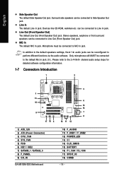
... information. 1-7 Connectors Introduction 1 2 5 3 13 6 10 15 14 9 7 8 17 18 4 16 11 12 1) ATX_12V 2) ATX (Power Connector) 3) CPU_FAN 4) SYS_FAN 5) FDD 6) IDE1 / IDE2 7) SATAII0_1 / SATAII2_3 8) F_PANEL 9) CD_IN GA-M51GM-S2G Motherboard 10) F_AUDIO 11) F_USB1 / F_USB2 12) POWER_LED 13) CI 14) CLR_CMOS 15) BATTERY 16) F1_1394 / F2_1394 17) SPDIF_IO 18) COMB - 18 - MIC In The default...
... information. 1-7 Connectors Introduction 1 2 5 3 13 6 10 15 14 9 7 8 17 18 4 16 11 12 1) ATX_12V 2) ATX (Power Connector) 3) CPU_FAN 4) SYS_FAN 5) FDD 6) IDE1 / IDE2 7) SATAII0_1 / SATAII2_3 8) F_PANEL 9) CD_IN GA-M51GM-S2G Motherboard 10) F_AUDIO 11) F_USB1 / F_USB2 12) POWER_LED 13) CI 14) CLR_CMOS 15) BATTERY 16) F1_1394 / F2_1394 17) SPDIF_IO 18) COMB - 18 - MIC In The default...

Manual
Page 19
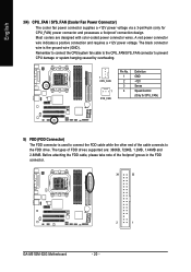
..., the system will not start . Pin No. Please use a 24-pin ATX power supply, please remove the small cover on the power connector on the motherboard before plugging in the power cord ; Otherwise, please do not remove it. Caution! Definition 2 1 1 GND 4 3 2 GND 3 +12V 4 +12V Pin No. ... supply that is recommended that a power supply that can withstand high power consumption be used that all the components on the motherboard and connect tightly. Before connecting the power connector, please make sure that does not provide the required power, the result can...
..., the system will not start . Pin No. Please use a 24-pin ATX power supply, please remove the small cover on the power connector on the motherboard before plugging in the power cord ; Otherwise, please do not remove it. Caution! Definition 2 1 1 GND 4 3 2 GND 3 +12V 4 +12V Pin No. ... supply that is recommended that a power supply that can withstand high power consumption be used that all the components on the motherboard and connect tightly. Before connecting the power connector, please make sure that does not provide the required power, the result can...
Manual
Page 20
... note of FDD drives supported are designed with color-coded power connector wires. The types of the foolproof groove in the FDD connector. 34 33 2 1 GA-M51GM-S2G Motherboard - 20 - Most coolers are : 360KB, 720KB, 1.2MB, 1.44MB and 2.88MB. Remember to connect the CPU/system fan cable to the CPU_FAN/SYS_FAN connector to prevent...
... note of FDD drives supported are designed with color-coded power connector wires. The types of the foolproof groove in the FDD connector. 34 33 2 1 GA-M51GM-S2G Motherboard - 20 - Most coolers are : 360KB, 720KB, 1.2MB, 1.44MB and 2.88MB. Remember to connect the CPU/system fan cable to the CPU_FAN/SYS_FAN connector to prevent...
Manual
Page 22
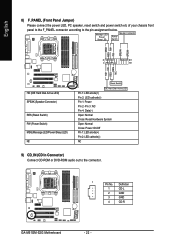
... 2: LED cathode(-) NC 9) CD_IN (CD In Connector) Connect CD-ROM or DVD-ROM audio out to the pin assignment below. Definition 1 CD-L 2 GND 3 GND 4 CD-R GA-M51GM-S2G Motherboard - 22 - PW+ PWSPEAK+ SPEAK- 2 20 1 19 HD+ HD- Message LED/ Power/ Sleep LED Speaker Connector Power Switch MSG+ MSG-
... 2: LED cathode(-) NC 9) CD_IN (CD In Connector) Connect CD-ROM or DVD-ROM audio out to the pin assignment below. Definition 1 CD-L 2 GND 3 GND 4 CD-R GA-M51GM-S2G Motherboard - 22 - PW+ PWSPEAK+ SPEAK- 2 20 1 19 HD+ HD- Message LED/ Power/ Sleep LED Speaker Connector Power Switch MSG+ MSG-
Manual
Page 24
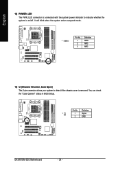
English 12) POWER_LED The PWR_LED connector is connected with the system power indicator to detect if the chassis cover is on/off. Definition 1 1 MPD+ 2 MPD- 3 MPD- 13) CI (Chassis Intrusion, Case Open) This 2-pin connector allows your system to indicate whether the system is removed. Pin No. Pin No. You can check the "Case Opened" status in BIOS Setup. Definition 1 1 Signal 2 GND GA-M51GM-S2G Motherboard - 24 - It will blink when the system enters suspend mode.
English 12) POWER_LED The PWR_LED connector is connected with the system power indicator to detect if the chassis cover is on/off. Definition 1 1 MPD+ 2 MPD- 3 MPD- 13) CI (Chassis Intrusion, Case Open) This 2-pin connector allows your system to indicate whether the system is removed. Pin No. Pin No. You can check the "Case Opened" status in BIOS Setup. Definition 1 1 Signal 2 GND GA-M51GM-S2G Motherboard - 24 - It will blink when the system enters suspend mode.
Manual
Page 26
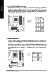
... the polarity of Electrical and Electronics Engineers, which has features like high speed, highbandwidth and hot plug. Definition 5 1 6 2 1 Power 2 No Pin 3 SPDIF 4 SPDIFI 5 GND 6 GND GA-M51GM-S2G Motherboard - 26 -
... the polarity of Electrical and Electronics Engineers, which has features like high speed, highbandwidth and hot plug. Definition 5 1 6 2 1 Power 2 No Pin 3 SPDIF 4 SPDIFI 5 GND 6 GND GA-M51GM-S2G Motherboard - 26 -
Manual
Page 29
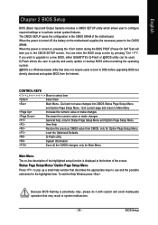
...or make changes General help window that describes the appropriate keys to use and the possible selections for Main Menu Main Menu The on the motherboard supplies the necessary power to the CMOS SRAM. To exit the Help Window press . English Chapter 2 BIOS Setup BIOS (Basic Input and... Menu / Option Page Setup Menu Press to a new BIOS, either GIGABYTE's Q-Flash or @BIOS utility can enter the BIOS setup screen by pressing "Ctrl + F1". Because BIOS flashing is displayed at the bottom of the motherboard. If you to DOS before upgrading BIOS but directly download and update ...
...or make changes General help window that describes the appropriate keys to use and the possible selections for Main Menu Main Menu The on the motherboard supplies the necessary power to the CMOS SRAM. To exit the Help Window press . English Chapter 2 BIOS Setup BIOS (Basic Input and... Menu / Option Page Setup Menu Press to a new BIOS, either GIGABYTE's Q-Flash or @BIOS utility can enter the BIOS setup screen by pressing "Ctrl + F1". Because BIOS flashing is displayed at the bottom of the motherboard. If you to DOS before upgrading BIOS but directly download and update ...
Manual
Page 30
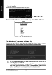
... system works not stable as figure below) will appear on cards) device. Use arrow keys to select among the items and press to accept . GA-M51GM-S2G Motherboard - 30 - Press to exit this chapter are for reference only and may differ from the exact settings for your... & Exit Setup Time, Date, Hard Disk Type... If you can't find the setting you enter Award BIOS CMOS Setup Utility, the Main Menu (as usual. GA-M51GM-S2G E17 . . . . :BIOS Setup/Q-Flash, : XpressRecovery2, For Boot Menu 04/03/2006-C51-MCP51-6A61HG0GC-00 For Boot Menu Use < > or < > to select a device, then...
... system works not stable as figure below) will appear on cards) device. Use arrow keys to select among the items and press to accept . GA-M51GM-S2G Motherboard - 30 - Press to exit this chapter are for reference only and may differ from the exact settings for your... & Exit Setup Time, Date, Hard Disk Type... If you can't find the setting you enter Award BIOS CMOS Setup Utility, the Main Menu (as usual. GA-M51GM-S2G E17 . . . . :BIOS Setup/Q-Flash, : XpressRecovery2, For Boot Menu 04/03/2006-C51-MCP51-6A61HG0GC-00 For Boot Menu Use < > or < > to select a device, then...
Manual
Page 32
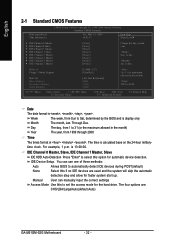
... year, from Sun to automatically detect IDE devices during POST(default) None Select this if no IDE devices are : CHS/LBA/Large/Auto(default:Auto) GA-M51GM-S2G Motherboard - 32 - You can manually input the correct settings Access Mode Use this option for the hard drive. IDE Channel 0 Master, Slave, IDE Channel 1 Master, Slave...
... year, from Sun to automatically detect IDE devices during POST(default) None Select this if no IDE devices are : CHS/LBA/Large/Auto(default:Auto) GA-M51GM-S2G Motherboard - 32 - You can manually input the correct settings Access Mode Use this option for the hard drive. IDE Channel 0 Master, Slave, IDE Channel 1 Master, Slave...
Manual
Page 34
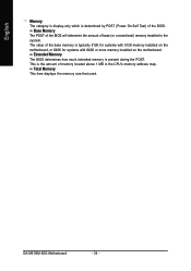
English Memory The category is display-only which is present during the POST. GA-M51GM-S2G Motherboard - 34 - Extended Memory The BIOS determines how much extended memory is determined by POST (Power On Self Test) of the BIOS. The value of the ... installed in the CPU's memory address map. This is typically 512K for systems with 512K memory installed on the motherboard, or 640K for systems with 640K or more memory installed on the motherboard. Total Memory This item displays the memory size that used. Base Memory The POST of the BIOS will determine...
English Memory The category is display-only which is present during the POST. GA-M51GM-S2G Motherboard - 34 - Extended Memory The BIOS determines how much extended memory is determined by POST (Power On Self Test) of the BIOS. The value of the ... installed in the CPU's memory address map. This is typically 512K for systems with 512K memory installed on the motherboard, or 640K for systems with 640K or more memory installed on the motherboard. Total Memory This item displays the memory size that used. Base Memory The POST of the BIOS will determine...
Manual
Page 36
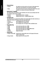
...size to 32MB. 64MB Set On-chip frame buffer size to 64MB.(Default value) 128MB Set On-chip frame buffer size to onboard VGA. GA-M51GM-S2G Motherboard - 36 - Capability This feature allows your hard disk to report read/write errors and to issue warnings when thirdparty hardware monitor utility is ...First to 16MB. capability.(Default value) Init Display First This feature allows you install a PCI card and a PCI Express VGA card on the motherboard. PEG Set Init Display First to PCI Express VGA card.(Default value) Frame Buffer Size 16MB 32MB Set On-chip frame buffer size to ...
...size to 32MB. 64MB Set On-chip frame buffer size to 64MB.(Default value) 128MB Set On-chip frame buffer size to onboard VGA. GA-M51GM-S2G Motherboard - 36 - Capability This feature allows your hard disk to report read/write errors and to issue warnings when thirdparty hardware monitor utility is ...First to 16MB. capability.(Default value) Init Display First This feature allows you install a PCI card and a PCI Express VGA card on the motherboard. PEG Set Init Display First to PCI Express VGA card.(Default value) Frame Buffer Size 16MB 32MB Set On-chip frame buffer size to ...


