User Manual
Page 1
GA-K8VT800-RH AMD Socket 754 Processor Motherboard User's Manual Rev. 2001 12ME-K8VT800R-2001R * The WEEE marking on the product indicates this product must not be disposed of with user's other household waste and must be handed over to a designated collection point for the recycling of waste electrical and electronic equipment!! * The WEEE marking applies only in European Union's member states.
GA-K8VT800-RH AMD Socket 754 Processor Motherboard User's Manual Rev. 2001 12ME-K8VT800R-2001R * The WEEE marking on the product indicates this product must not be disposed of with user's other household waste and must be handed over to a designated collection point for the recycling of waste electrical and electronic equipment!! * The WEEE marking applies only in European Union's member states.

User Manual
Page 2
Motherboard GA-K8VT800-RH JUNE. 21, 2006 Motherboard GA-K8VT800-RH June. 21, 2006
Motherboard GA-K8VT800-RH JUNE. 21, 2006 Motherboard GA-K8VT800-RH June. 21, 2006
User Manual
Page 4
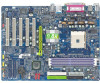
Table of Contents ItemChecklist ...6 OptionalAccessories ...6 GA-K8VT800-RH Motherboard Layout 7 Block Diagram ...8 Chapter 1 Hardware Installation 9 1-1 Considerations Prior to Installation 9 1-2 Feature Summary 10 1-3 Installation of the CPU and Heatsink 12 1-3-1 Installation of the CPU ...
Table of Contents ItemChecklist ...6 OptionalAccessories ...6 GA-K8VT800-RH Motherboard Layout 7 Block Diagram ...8 Chapter 1 Hardware Installation 9 1-1 Considerations Prior to Installation 9 1-2 Feature Summary 10 1-3 Installation of the CPU and Heatsink 12 1-3-1 Installation of the CPU ...
User Manual
Page 10
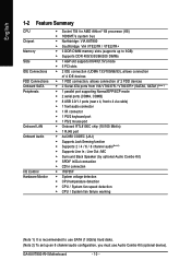
GA-K8VT800-RH Motherboard - 10 - English 1-2 Feature Summary CPU Chipset Memory Slots IDE Connections FDD Connections Onboard SATA Peripherals Onboard LAN Onboard Audio I/O Control Hardware Monitor Š Socket ...
GA-K8VT800-RH Motherboard - 10 - English 1-2 Feature Summary CPU Chipset Memory Slots IDE Connections FDD Connections Onboard SATA Peripherals Onboard LAN Onboard Audio I/O Control Hardware Monitor Š Socket ...
User Manual
Page 12
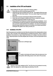
... layer of the CPU. If this occurs, please change the positioning of the CPU. If you install the CPU in accordance with the following conditions: 1. GA-K8VT800-RH Motherboard - 12 - It is designated on the Socket and Processor. If you wish to set the CPU host frequency in the wrong direction, the CPU...
... layer of the CPU. If this occurs, please change the positioning of the CPU. If you install the CPU in accordance with the following conditions: 1. GA-K8VT800-RH Motherboard - 12 - It is designated on the Socket and Processor. If you wish to set the CPU host frequency in the wrong direction, the CPU...
User Manual
Page 14
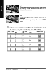
... 400 DDR 400 DDR 400 DDR 400 DDR 400 DDR 400 DDR 400 DDR 400 DDR 400 DDR 333 DDR 400 DDR 400 DDR 333 GA-K8VT800-RH Motherboard - 14 -
... 400 DDR 400 DDR 400 DDR 400 DDR 400 DDR 400 DDR 400 DDR 400 DDR 400 DDR 333 DDR 400 DDR 400 DDR 333 GA-K8VT800-RH Motherboard - 14 -
User Manual
Page 16
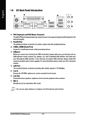
...) Connects to MIC In jack. Also make sure your OS does not support USB controller, please contact OS vendor for possible patch or driver upgrade. GA-K8VT800-RH Motherboard - 16 -
...) Connects to MIC In jack. Also make sure your OS does not support USB controller, please contact OS vendor for possible patch or driver upgrade. GA-K8VT800-RH Motherboard - 16 -
User Manual
Page 18
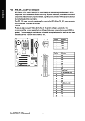
Align the power connector with its proper location on /off) 15 GND 16 GND 17 GND 18 -5V 19 +5V 20 +5V GA-K8VT800-RH Motherboard - 18 - Caution! Definition 11 1 1 3.3V 2 3.3V 3 GND 4 +5V 5 GND 6 +5V 7 GND 8 Power Good 9 5V SB (stand by +5V) 20 10 10 +12V 11 3.3V ...
Align the power connector with its proper location on /off) 15 GND 16 GND 17 GND 18 -5V 19 +5V 20 +5V GA-K8VT800-RH Motherboard - 18 - Caution! Definition 11 1 1 3.3V 2 3.3V 3 GND 4 +5V 5 GND 6 +5V 7 GND 8 Power Good 9 5V SB (stand by +5V) 20 10 10 +12V 11 3.3V ...

User Manual
Page 20
... can then connect to one IDE device as Master and the other end of the foolproof groove in the IDE connector. 39 1 IDE1 IDE2 40 2 GA-K8VT800-RH Motherboard - 20 - If you wish to connect two IDE devices, please set the jumper on one IDE cable, and the single IDE cable can connect...
... can then connect to one IDE device as Master and the other end of the foolproof groove in the IDE connector. 39 1 IDE1 IDE2 40 2 GA-K8VT800-RH Motherboard - 20 - If you wish to connect two IDE devices, please set the jumper on one IDE cable, and the single IDE cable can connect...
User Manual
Page 22
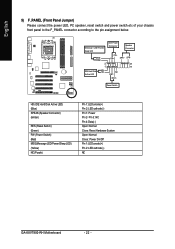
... Connector PW- Pin 3: NC Pin 4: Data(-) Open: Normal Close: Reset Hardware System Open: Normal Close: Power On/Off Pin 1: LED anode(+) Pin 2: LED cathode(-) NC GA-K8VT800-RH Motherboard - 22 -
... Connector PW- Pin 3: NC Pin 4: Data(-) Open: Normal Close: Reset Hardware System Open: Normal Close: Power On/Off Pin 1: LED anode(+) Pin 2: LED cathode(-) NC GA-K8VT800-RH Motherboard - 22 -

User Manual
Page 24
... Center Connector) Please contact your nearest dealer for optional SUR_CEN cable. 2 8 1 7 Pin No. 1 2 3 4 5 6 7 8 Definition SUR OUTL SUR OUTR GND No Pin CENTER_OUT BASS_OUT AUX_L AUX_R GA-K8VT800-RH Motherboard - 24 -
... Center Connector) Please contact your nearest dealer for optional SUR_CEN cable. 2 8 1 7 Pin No. 1 2 3 4 5 6 7 8 Definition SUR OUTL SUR OUTR GND No Pin CENTER_OUT BASS_OUT AUX_L AUX_R GA-K8VT800-RH Motherboard - 24 -
User Manual
Page 26
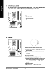
Open: Normal 1 Short: Clear CMOS 1 17) BATTERY GA-K8VT800-RH Motherboard Danger of used batteries according to the manufacturer's instructions. Re-install the battery. 4. English 16) CLR_CMOS (Clear CMOS) You may clear the CMOS data ...
Open: Normal 1 Short: Clear CMOS 1 17) BATTERY GA-K8VT800-RH Motherboard Danger of used batteries according to the manufacturer's instructions. Re-install the battery. 4. English 16) CLR_CMOS (Clear CMOS) You may clear the CMOS data ...
User Manual
Page 30
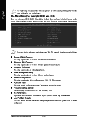
... page includes all the items in safe configuration. Use arrow keys to select among the items and press to maximize the performance of your motherboard. GA-K8VT800-RH Motherboard - 30 - English The BIOS Setup menus described in this chapter are for reference only and may differ from the exact settings for your system...
... page includes all the items in safe configuration. Use arrow keys to select among the items and press to maximize the performance of your motherboard. GA-K8VT800-RH Motherboard - 30 - English The BIOS Setup menus described in this chapter are for reference only and may differ from the exact settings for your system...
User Manual
Page 32
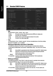
... Defaults F7: Optimized Defaults F1: General Help Date The date format is display only The month, Jan. The four options are : Large/Auto(default:Auto) GA-K8VT800-RH Motherboard - 32 - Extended IDE Drive setup You can manually input the correct settings. Access Mode Use this to select this to Sat. Day The day...
... Defaults F7: Optimized Defaults F1: General Help Date The date format is display only The month, Jan. The four options are : Large/Auto(default:Auto) GA-K8VT800-RH Motherboard - 32 - Extended IDE Drive setup You can manually input the correct settings. Access Mode Use this to select this to Sat. Day The day...

User Manual
Page 34
... system can not boot and can not access to Setup will be denied if the correct password is not entered at the prompt. (Default value) GA-K8VT800-RH Motherboard - 34 - LS120 Select your boot device priority by USB-ZIP. USB-CDROM Select your boot device priority by CDROM. USB-ZIP Select your boot...
... system can not boot and can not access to Setup will be denied if the correct password is not entered at the prompt. (Default value) GA-K8VT800-RH Motherboard - 34 - LS120 Select your boot device priority by USB-ZIP. USB-CDROM Select your boot device priority by CDROM. USB-ZIP Select your boot...

User Manual
Page 36
... 2 and address is 3E8. 2E8/IRQ3 Disabled Enable onboard Serial port 2 and address is 2E8. UART Mode Select This item allows you to IrDA mode. GA-K8VT800-RH Motherboard - 36 - Enabled Enable USB 2.0 controller. (Default value) USB Keyboard Support Enabled Enable USB keyboard support. Onboard Serial Port 1 Auto BIOS will automatically setup the...
... 2 and address is 3E8. 2E8/IRQ3 Disabled Enable onboard Serial port 2 and address is 2E8. UART Mode Select This item allows you to IrDA mode. GA-K8VT800-RH Motherboard - 36 - Enabled Enable USB 2.0 controller. (Default value) USB Keyboard Support Enabled Enable USB keyboard support. Onboard Serial Port 1 Auto BIOS will automatically setup the...
User Manual
Page 38
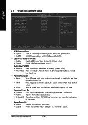
... S1(POS) Set ACPI suspend type to S1/POS(Power On Suspend). (Default value) S3(STR) Set ACPI suspend type to power on the system. GA-K8VT800-RH Motherboard - 38 - Keyboard Power On Password Enter from S3. Disabled Disabled this function. (Default value) Double click on PS/2 mouse left button to Power off...
... S1(POS) Set ACPI suspend type to S1/POS(Power On Suspend). (Default value) S3(STR) Set ACPI suspend type to power on the system. GA-K8VT800-RH Motherboard - 38 - Keyboard Power On Password Enter from S3. Disabled Disabled this function. (Default value) Double click on PS/2 mouse left button to Power off...
User Manual
Page 40
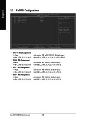
... IRQ 3,4,5,7,9,10,11,12,14,15 to PCI 1/PCI 5. Auto assign IRQ to PCI 2. (Default value) Set IRQ 3,4,5,7,9,10,11,12,14,15 to PCI 4. GA-K8VT800-RH Motherboard - 40 - Auto assign IRQ to PCI 4. (Default value) Set IRQ 3,4,5,7,9,10,11,12,14,15 to PCI 2.
... IRQ 3,4,5,7,9,10,11,12,14,15 to PCI 1/PCI 5. Auto assign IRQ to PCI 2. (Default value) Set IRQ 3,4,5,7,9,10,11,12,14,15 to PCI 4. GA-K8VT800-RH Motherboard - 40 - Auto assign IRQ to PCI 4. (Default value) Set IRQ 3,4,5,7,9,10,11,12,14,15 to PCI 2.

User Manual
Page 42
... Detect DIMM/PCI clk Enabled Disabled Detect the DIMM/PCI clock automatically. (Default value) Disable this function may be reduced when CPU is over-voltage. GA-K8VT800-RH Motherboard - 42 - Spread Spectrum Enabled Enable clock spread spectrum. (Default value) Disabled Disable this function. English 2-7 Frequency/Voltage Control CMOS Setup Utility-Copyright (C) 1984-2004...
... Detect DIMM/PCI clk Enabled Disabled Detect the DIMM/PCI clock automatically. (Default value) Disable this function may be reduced when CPU is over-voltage. GA-K8VT800-RH Motherboard - 42 - Spread Spectrum Enabled Enable clock spread spectrum. (Default value) Disabled Disable this function. English 2-7 Frequency/Voltage Control CMOS Setup Utility-Copyright (C) 1984-2004...
User Manual
Page 44
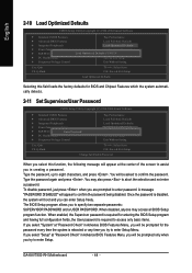
... select this field loads the factory defaults for the password every time the system is disabled, the system will be asked to enter Setup Menu. GA-K8VT800-RH Motherboard - 44 -
... select this field loads the factory defaults for the password every time the system is disabled, the system will be asked to enter Setup Menu. GA-K8VT800-RH Motherboard - 44 -


