Manual
Page 1
GA-HA65M-UD3H-B3 LGA1155 socket motherboard for Intel® Core™ i7 processors/ Intel® Core™ i5 processors/Intel® Core™ i3 processors/ Intel® Pentium® processors/Intel® Celeron® processors User's Manual Rev. 1001 12ME-A65M3HB-1001R
GA-HA65M-UD3H-B3 LGA1155 socket motherboard for Intel® Core™ i7 processors/ Intel® Core™ i5 processors/Intel® Core™ i3 processors/ Intel® Pentium® processors/Intel® Celeron® processors User's Manual Rev. 1001 12ME-A65M3HB-1001R

Manual
Page 2
Motherboard GA-HA65M-UD3H-B3 Feb. 25, 2011 Motherboard GA-HA65M-UD3H-B3 Feb. 25, 2011
Motherboard GA-HA65M-UD3H-B3 Feb. 25, 2011 Motherboard GA-HA65M-UD3H-B3 Feb. 25, 2011

Manual
Page 3
...translated, transmitted, or published in this manual may be made by copyright laws and is the property of the motherboard is protected by GIGABYTE without GIGABYTE's prior written permission. Disclaimer Information in this manual are legally registered to the specifications and features in this : ..."REV: X.X." All rights reserved. For example, "REV: 1.0" means the revision of GIGABYTE. Example: Check your motherboard looks like this manual is 1.0. Changes to their respective owners. For product-related information, check on our website at:...
...translated, transmitted, or published in this manual may be made by copyright laws and is the property of the motherboard is protected by GIGABYTE without GIGABYTE's prior written permission. Disclaimer Information in this manual are legally registered to the specifications and features in this : ..."REV: X.X." All rights reserved. For example, "REV: 1.0" means the revision of GIGABYTE. Example: Check your motherboard looks like this manual is 1.0. Changes to their respective owners. For product-related information, check on our website at:...

Manual
Page 4
Table of Contents Box Contents...6 Optional Items...6 GA-HA65M-UD3H-B3 Motherboard Layout 7 GA-HA65M-UD3H-B3 Motherboard Block Diagram 8 Chapter 1 Hardware Installation 9 1-1 Installation Precautions 9 1-2 Product Specifications 10 1-3 Installing the CPU and CPU Cooler 13 1-3-1 Installing the CPU 13 1-3-2 Installing the CPU Cooler ...
Table of Contents Box Contents...6 Optional Items...6 GA-HA65M-UD3H-B3 Motherboard Layout 7 GA-HA65M-UD3H-B3 Motherboard Block Diagram 8 Chapter 1 Hardware Installation 9 1-1 Installation Precautions 9 1-2 Product Specifications 10 1-3 Installing the CPU and CPU Cooler 13 1-3-1 Installing the CPU 13 1-3-2 Installing the CPU Cooler ...

Manual
Page 6
Optional Items 2-port USB 2.0 bracket (Part No. 12CR1-1UB030-5*R) 2-port SATA power cable (Part No. 12CF1-2SERPW-0*R) COM port cable (Part No. 12CF1-1CM001-3*R) - 6 - The box contents are for reference only. Box Contents GA-HA65M-UD3H-B3 motherboard Motherboard driver disk User's Manual Quick Installation Guide Two SATA cables I/O Shield • The box contents above are subject to change without notice. • The motherboard image is for reference only and the actual items shall depend on the product package you obtain.
Optional Items 2-port USB 2.0 bracket (Part No. 12CR1-1UB030-5*R) 2-port SATA power cable (Part No. 12CF1-2SERPW-0*R) COM port cable (Part No. 12CF1-1CM001-3*R) - 6 - The box contents are for reference only. Box Contents GA-HA65M-UD3H-B3 motherboard Motherboard driver disk User's Manual Quick Installation Guide Two SATA cables I/O Shield • The box contents above are subject to change without notice. • The motherboard image is for reference only and the actual items shall depend on the product package you obtain.

Manual
Page 7
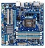
GA-HA65M-UD3H-B3 Motherboard Layout DDR3_1 DDR3_2 DDR3_3 DDR3_4 KB_USB ATX_12V PHASE LED VGA_DVI HDMI LGA1155 ATX USB30_20 B_BIOS M_BIOS USB_LAN Etron EJ168 AUDIO BAT PCIEX16 CPU_FAN Realtek RTL8111E PCI1 PCIe to PCI Bridge PCI2 SPDIF_O CODEC PCIEX1 F_AUDIO SYS_FAN iTE IT8728 GA-HA65M-UD3H-B3 Marvell 88SE9172 F_USB30 Etron EJ168 F_USB2 Intel® H61 GSATA3_5 GSATA3_4 SATA2_1SATA2_0 COM CLR_CMOS F_USB1 SATA2_3 SATA2_2 F_PANEL - 7 -
GA-HA65M-UD3H-B3 Motherboard Layout DDR3_1 DDR3_2 DDR3_3 DDR3_4 KB_USB ATX_12V PHASE LED VGA_DVI HDMI LGA1155 ATX USB30_20 B_BIOS M_BIOS USB_LAN Etron EJ168 AUDIO BAT PCIEX16 CPU_FAN Realtek RTL8111E PCI1 PCIe to PCI Bridge PCI2 SPDIF_O CODEC PCIEX1 F_AUDIO SYS_FAN iTE IT8728 GA-HA65M-UD3H-B3 Marvell 88SE9172 F_USB30 Etron EJ168 F_USB2 Intel® H61 GSATA3_5 GSATA3_4 SATA2_1SATA2_0 COM CLR_CMOS F_USB1 SATA2_3 SATA2_2 F_PANEL - 7 -

Manual
Page 8
GA-HA65M-UD3H-B3 Motherboard Block Diagram 1 PCI Express x16 LGA1155 CPU CPU CLK+/- (100 MHz) DDR3 1333/1066/800 MHz Dual Channel Memory PCIe CLK (100 MHz) x16 PCI ...
GA-HA65M-UD3H-B3 Motherboard Block Diagram 1 PCI Express x16 LGA1155 CPU CPU CLK+/- (100 MHz) DDR3 1333/1066/800 MHz Dual Channel Memory PCIe CLK (100 MHz) x16 PCI ...

Manual
Page 9
...off. •• Before turning on the power, make sure they are connected tightly and securely. •• When handling the motherboard, avoid touching any installation steps or have a problem related to the use of electrostatic discharge (ESD). These stickers are required for ...an electrostatic shielding container. •• Before unplugging the power supply cable from the power outlet before installing or removing the motherboard or other hardware components. •• When connecting hardware components to the internal connectors on the computer power during the ...
...off. •• Before turning on the power, make sure they are connected tightly and securely. •• When handling the motherboard, avoid touching any installation steps or have a problem related to the use of electrostatic discharge (ESD). These stickers are required for ...an electrostatic shielding container. •• Before unplugging the power supply cable from the power outlet before installing or removing the motherboard or other hardware components. •• When connecting hardware components to the internal connectors on the computer power during the ...

Manual
Page 12
... ŠŠ Support for Xpress Install ŠŠ Support for Xpress Recovery2 ŠŠ Support for EasyTune * Available functions in EasyTune may differ by motherboard model. ŠŠ Support for Dynamic Energy Saver™ 2 ŠŠ Support for Smart 6™ ŠŠ Support for Auto Green Š...System ŠŠ Support for Microsoft® Windows 7/Vista/XP Form Factor ŠŠ Micro ATX Form Factor; 24.4cm x 24.4cm * GIGABYTE reserves the right to make any changes to the product specifications and product-related information without prior notice.
... ŠŠ Support for Xpress Install ŠŠ Support for Xpress Recovery2 ŠŠ Support for EasyTune * Available functions in EasyTune may differ by motherboard model. ŠŠ Support for Dynamic Energy Saver™ 2 ŠŠ Support for Smart 6™ ŠŠ Support for Auto Green Š...System ŠŠ Support for Microsoft® Windows 7/Vista/XP Form Factor ŠŠ Micro ATX Form Factor; 24.4cm x 24.4cm * GIGABYTE reserves the right to make any changes to the product specifications and product-related information without prior notice.

Manual
Page 13
... for the latest CPU support list.) •• Always turn on the computer if the CPU cooler is not recommended that the motherboard supports the CPU. (Go to GIGABYTE's website for the peripherals. LGA1155 CPU Socket Alignment Key Alignment Key Pin One Corner of the CPU may locate the notches on both... power outlet before installing the CPU to prevent hardware damage. •• Locate the pin one of the CPU. Locate the alignment keys on the motherboard CPU socket and the notches on the CPU - 13 -
... for the latest CPU support list.) •• Always turn on the computer if the CPU cooler is not recommended that the motherboard supports the CPU. (Go to GIGABYTE's website for the peripherals. LGA1155 CPU Socket Alignment Key Alignment Key Pin One Corner of the CPU may locate the notches on both... power outlet before installing the CPU to prevent hardware damage. •• Locate the pin one of the CPU. Locate the alignment keys on the motherboard CPU socket and the notches on the CPU - 13 -

Manual
Page 14
... completely lift the CPU socket lever and the metal load plate will be lifted as shown. Step 5: Push the CPU socket lever back into the motherboard CPU socket. Hardware Installation - 14 - Follow the steps below to the CPU. Step 1: Gently press the CPU socket lever handle down on the rear grip...
... completely lift the CPU socket lever and the metal load plate will be lifted as shown. Step 5: Push the CPU socket lever back into the motherboard CPU socket. Hardware Installation - 14 - Follow the steps below to the CPU. Step 1: Gently press the CPU socket lever handle down on the rear grip...

Manual
Page 15
... the steps below to your CPU cooler installation manual for instructions on installing the cooler.) Step 5: After the installation, check the back of the motherboard. If the push pin is inserted as the example cooler.) Direction of the Arrow Sign on the Male Push Pin Male Push Pin The Top... of thermal grease on the surface of the installed CPU. Inadequately removing the CPU cooler may adhere to the CPU fan header (CPU_FAN) on the motherboard. Step 2: Before installing the cooler, note the direction of the arrow sign on the male push pin. (Turning the push pin along the direction...
... the steps below to your CPU cooler installation manual for instructions on installing the cooler.) Step 5: After the installation, check the back of the motherboard. If the push pin is inserted as the example cooler.) Direction of the Arrow Sign on the Male Push Pin Male Push Pin The Top... of thermal grease on the surface of the installed CPU. Inadequately removing the CPU cooler may adhere to the CPU fan header (CPU_FAN) on the motherboard. Step 2: Before installing the cooler, note the direction of the arrow sign on the male push pin. (Turning the push pin along the direction...

Manual
Page 16
...one DDR3 memory module is installed. 222 When enabling Dual Channel mode with two or four memory modules, it /them must be used. (Go to GIGABYTE's website for optimum performance. • If one or two single-sided memory modules are to be installed, be sure to install it is recommended ...that the motherboard supports the memory. After the memory is recommended that memory of the same capacity, brand, speed, and chips be installed in the DDR3_1 and ...
...one DDR3 memory module is installed. 222 When enabling Dual Channel mode with two or four memory modules, it /them must be used. (Go to GIGABYTE's website for optimum performance. • If one or two single-sided memory modules are to be installed, be sure to install it is recommended ...that the motherboard supports the memory. After the memory is recommended that memory of the same capacity, brand, speed, and chips be installed in the DDR3_1 and ...

Manual
Page 17
... socket. As indicated in the picture on the memory and insert it can only fit in the memory sockets. Place the memory module on this motherboard. 1-4-2 Installing a Memory Before installing a memory module, make sure to turn off the computer and unplug the power cord from the power outlet to prevent damage...
... socket. As indicated in the picture on the memory and insert it can only fit in the memory sockets. Place the memory module on this motherboard. 1-4-2 Installing a Memory Before installing a memory module, make sure to turn off the computer and unplug the power cord from the power outlet to prevent damage...

Manual
Page 18
... the card and then pull the card straight up from the power outlet before you begin to install an expansion card: • Make sure the motherboard supports the expansion card. Make sure the card is fully seated in the expansion slot. 111 Locate an expansion slot that came with your card...
... the card and then pull the card straight up from the power outlet before you begin to install an expansion card: • Make sure the motherboard supports the expansion card. Make sure the card is fully seated in the expansion slot. 111 Locate an expansion slot that came with your card...

Manual
Page 20
... Jack (Green) The default line out jack. Refer to a back panel connector, first remove the cable from your device and then remove it from the motherboard. •• When removing the cable, pull it side to side to 1 Gbps data rate. Do not rock it straight out from the connector. ... audio jack for USB devices such as an optical drive, walkman, etc. Use this audio jack to this audio jack for the Onboard Graphics: This motherboard provides three video output ports: D-Sub, DVI-D, and HDMI. This jack can be connected to connect side speakers in jack. Mic In Jack (Pink) The...
... Jack (Green) The default line out jack. Refer to a back panel connector, first remove the cable from your device and then remove it from the motherboard. •• When removing the cable, pull it side to side to 1 Gbps data rate. Do not rock it straight out from the connector. ... audio jack for USB devices such as an optical drive, walkman, etc. Use this audio jack to this audio jack for the Onboard Graphics: This motherboard provides three video output ports: D-Sub, DVI-D, and HDMI. This jack can be connected to connect side speakers in jack. Mic In Jack (Pink) The...

Manual
Page 21
... and your devices are compliant with the connectors you wish to connect. •• Before installing the devices, be sure to the connector on the motherboard. - 21 - 1-7 Internal Connectors 1 3 15 2 5 6 13 10 94 12 11 14 7 8 1) ATX_12V 2) ATX 3) CPU_FAN 4) SYS_FAN 5) BAT 6) GSATA3_4/5 7) SATA2_0/1/2/3 8) F_PANEL 9) F_AUDIO 10) SPDIF_O 11) F_USB1/2 12) F_USB30...
... and your devices are compliant with the connectors you wish to connect. •• Before installing the devices, be sure to the connector on the motherboard. - 21 - 1-7 Internal Connectors 1 3 15 2 5 6 13 10 94 12 11 14 7 8 1) ATX_12V 2) ATX 3) CPU_FAN 4) SYS_FAN 5) BAT 6) GSATA3_4/5 7) SATA2_0/1/2/3 8) F_PANEL 9) F_AUDIO 10) SPDIF_O 11) F_USB1/2 12) F_USB30...

Manual
Page 22
If the 12V power connector is turned off and all the components on the motherboard. To meet expansion requirements, it is used that can withstand high power consumption be used (500W or greater). If a power supply is recommended that a power ...
If the 12V power connector is turned off and all the components on the motherboard. To meet expansion requirements, it is used that can withstand high power consumption be used (500W or greater). If a power supply is recommended that a power ...

Manual
Page 23
... of the positive side (+) and the negative side (-) of the battery (the positive side should face up). •• Used batteries must be lost. The motherboard supports CPU fan speed control, which requires the use a metal object like a screwdriver to the CPU or the system may be handled in the correct... battery. 444 Plug in damage to touch the positive and negative terminals of a CPU fan with local environmental regulations. - 23 - 3/4) CPU_FAN/SYS_FAN (Fan Headers) The motherboard has a 4-pin CPU fan header (CPU_FAN), a 4-pin system fan header (SYS_FAN).
... of the positive side (+) and the negative side (-) of the battery (the positive side should face up). •• Used batteries must be lost. The motherboard supports CPU fan speed control, which requires the use a metal object like a screwdriver to the CPU or the system may be handled in the correct... battery. 444 Plug in damage to touch the positive and negative terminals of a CPU fan with local environmental regulations. - 23 - 3/4) CPU_FAN/SYS_FAN (Fan Headers) The motherboard has a 4-pin CPU fan header (CPU_FAN), a 4-pin system fan header (SYS_FAN).

Manual
Page 26
... back panel audio connections simultaneously. If your chassis provides an AC'97 front panel audio module, refer to the instructions on both of the motherboard header. F_AUDIO(H) For HD Front Panel Audio: For AC'97 Front Panel Audio: 9 1 Pin No. Definition 1 SPDIFO 2 GND Hardware... card. 1 Pin No. Incorrect connection between the module connector and the motherboard header will be present on how to the graphics card and have digital audio output from your motherboard to your motherboard to Chapter 5, "Configuring 2/4/5.1/7.1-Channel Audio." •• Some chassis provide...
... back panel audio connections simultaneously. If your chassis provides an AC'97 front panel audio module, refer to the instructions on both of the motherboard header. F_AUDIO(H) For HD Front Panel Audio: For AC'97 Front Panel Audio: 9 1 Pin No. Definition 1 SPDIFO 2 GND Hardware... card. 1 Pin No. Incorrect connection between the module connector and the motherboard header will be present on how to the graphics card and have digital audio output from your motherboard to your motherboard to Chapter 5, "Configuring 2/4/5.1/7.1-Channel Audio." •• Some chassis provide...


