
Manual
Page 3
... Disclaimer Information in this manual are legally registered to their respective owners. Check your motherboard looks like this manual may be made by any form or by GIGABYTE without GIGABYTE's prior written permission. The trademarks mentioned in this manual may be reproduced, copied... "REV: X.X." For product-related information, check on our website at: http://www.gigabyte.com Identifying Your Motherboard Revision The revision number on your motherboard revision before updating motherboard BIOS, drivers, or when looking for technical information. No part of the product, ...
... Disclaimer Information in this manual are legally registered to their respective owners. Check your motherboard looks like this manual may be made by any form or by GIGABYTE without GIGABYTE's prior written permission. The trademarks mentioned in this manual may be reproduced, copied... "REV: X.X." For product-related information, check on our website at: http://www.gigabyte.com Identifying Your Motherboard Revision The revision number on your motherboard revision before updating motherboard BIOS, drivers, or when looking for technical information. No part of the product, ...
Manual
Page 4
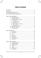
Table of Contents Box Contents...6 Optional Items...6 GA-H77M-HD3 Motherboard Layout 7 GA-H77M-HD3 Motherboard Block Diagram 8 Chapter 1 Hardware Installation 9 1-1 Installation Precautions 9 1-2 Product Specifications 10 1-3 Installing the CPU and CPU Cooler 13 1-3-1 Installing the CPU...13 1-3-2 Installing the CPU Cooler ...
Table of Contents Box Contents...6 Optional Items...6 GA-H77M-HD3 Motherboard Layout 7 GA-H77M-HD3 Motherboard Block Diagram 8 Chapter 1 Hardware Installation 9 1-1 Installation Precautions 9 1-2 Product Specifications 10 1-3 Installing the CPU and CPU Cooler 13 1-3-1 Installing the CPU...13 1-3-2 Installing the CPU Cooler ...
Manual
Page 6
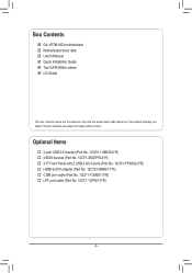
GA-H77M-HD3 motherboard ;; Two SATA 6Gb/s cables ;; Optional Items †† 2-port USB 2.0 bracket (Part No. 12CR1-1UB030-6*R) †† eSATA bracket (Part No. 12CF1-3SATPW-4*R) †† 3.5" Front Panel with 2 USB 3.0/2.0 ports (Part No. 12CR1-FPX582-0*R) †† HDMI-to change without notice. Motherboard driver disk ;; I/O Shield The box contents above are subject to...
GA-H77M-HD3 motherboard ;; Two SATA 6Gb/s cables ;; Optional Items †† 2-port USB 2.0 bracket (Part No. 12CR1-1UB030-6*R) †† eSATA bracket (Part No. 12CF1-3SATPW-4*R) †† 3.5" Front Panel with 2 USB 3.0/2.0 ports (Part No. 12CR1-FPX582-0*R) †† HDMI-to change without notice. Motherboard driver disk ;; I/O Shield The box contents above are subject to...
Manual
Page 7
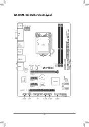
CLR_CMOS F_PANEL GA-H77M-HD3 Motherboard Layout KB_MS_USB ATX_12V_2X4 VGA DVI ATX HDMI R_USB30 LGA1155 R_USB USB_LAN AUDIO CPU_FAN SYS_FAN Realtek GbE LAN GA-H77M-HD3 M_BIOS iTE Super I/O PCIEX16 PCIEX1_1 PCIEX1_2 BAT PCIe to PCI Bridge Intel® H77 SATA2 4 3 CODEC PCI F_AUDIO COM SATA2 5 LPT F_USB2 F_USB1 F_USB30 DDR3_1 DDR3_2 SATA2 2 SATA3 0 SATA3 1 B_BIOS - 7 -
CLR_CMOS F_PANEL GA-H77M-HD3 Motherboard Layout KB_MS_USB ATX_12V_2X4 VGA DVI ATX HDMI R_USB30 LGA1155 R_USB USB_LAN AUDIO CPU_FAN SYS_FAN Realtek GbE LAN GA-H77M-HD3 M_BIOS iTE Super I/O PCIEX16 PCIEX1_1 PCIEX1_2 BAT PCIe to PCI Bridge Intel® H77 SATA2 4 3 CODEC PCI F_AUDIO COM SATA2 5 LPT F_USB2 F_USB1 F_USB30 DDR3_1 DDR3_2 SATA2 2 SATA3 0 SATA3 1 B_BIOS - 7 -
Manual
Page 8
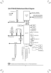
GA-H77M-HD3 Motherboard Block Diagram 1 PCI Express x16 PCIe CLK (100 MHz) LGA1155 CPU CPU CLK+/- (100 MHz) DDR3 1600/1333/1066 MHz Dual Channel Memory PCI Express ...
GA-H77M-HD3 Motherboard Block Diagram 1 PCI Express x16 PCIe CLK (100 MHz) LGA1155 CPU CPU CLK+/- (100 MHz) DDR3 1600/1333/1066 MHz Dual Channel Memory PCI Express ...

Manual
Page 9
...an ESD wrist strap, keep your hands dry and first touch a metal object to eliminate static electricity. •• Prior to installing the motherboard, please have a problem related to the use of your dealer. Hardware Installation These stickers are required for warranty validation. •• Always... remove the AC power by your hardware components are no leftover screws or metal components placed on the motherboard or within the computer casing. •• Do not place the computer system on an uneven surface. •• Do not ...
...an ESD wrist strap, keep your hands dry and first touch a metal object to eliminate static electricity. •• Prior to installing the motherboard, please have a problem related to the use of your dealer. Hardware Installation These stickers are required for warranty validation. •• Always... remove the AC power by your hardware components are no leftover screws or metal components placed on the motherboard or within the computer casing. •• Do not place the computer system on an uneven surface. •• Do not ...

Manual
Page 12
... ŠŠ Support for @BIOS Support for Q-Flash Support for Xpress Install Support for the software listed in EasyTune may differ by motherboard model. Support for eXtreme Hard Drive (X.H.D) Support for Smart Recovery 2 Support for Auto Green Support for ON/OFF Charge Support for Q-...174; Smart Connect Technology Support for Microsoft Windows 8/7/XP Form Factor ŠŠ Micro ATX Form Factor; 24.4cm x 17.4cm * GIGABYTE reserves the right to make any changes to the product specifications and product-related information without prior notice. * Please visit the Support & Downloads...
... ŠŠ Support for @BIOS Support for Q-Flash Support for Xpress Install Support for the software listed in EasyTune may differ by motherboard model. Support for eXtreme Hard Drive (X.H.D) Support for Smart Recovery 2 Support for Auto Green Support for ON/OFF Charge Support for Q-...174; Smart Connect Technology Support for Microsoft Windows 8/7/XP Form Factor ŠŠ Micro ATX Form Factor; 24.4cm x 17.4cm * GIGABYTE reserves the right to make any changes to the product specifications and product-related information without prior notice. * Please visit the Support & Downloads...

Manual
Page 13
...Key Pin One Corner of the CPU Socket LGA1155 CPU Notch Notch Triangle Pin One Marking on the CPU. Locate the alignment keys on the motherboard CPU socket and the notches on the CPU - 13 - The CPU cannot be set the frequency beyond hardware specifications since it does not...for the latest CPU support list.) •• Always turn on the computer if the CPU cooler is not recommended that the motherboard supports the CPU. (Go to GIGABYTE's website for the peripherals. 1-3 Installing the CPU and CPU Cooler Read the following guidelines before you begin to install the CPU: ...
...Key Pin One Corner of the CPU Socket LGA1155 CPU Notch Notch Triangle Pin One Marking on the CPU. Locate the alignment keys on the motherboard CPU socket and the notches on the CPU - 13 - The CPU cannot be set the frequency beyond hardware specifications since it does not...for the latest CPU support list.) •• Always turn on the computer if the CPU cooler is not recommended that the motherboard supports the CPU. (Go to GIGABYTE's website for the peripherals. 1-3 Installing the CPU and CPU Cooler Read the following guidelines before you begin to install the CPU: ...

Manual
Page 14
Follow the steps below to correctly install the CPU into the motherboard CPU socket. •• Before installing the CPU, make sure the front end of engaging the lever. Save the cover properly and replace it when ...
Follow the steps below to correctly install the CPU into the motherboard CPU socket. •• Before installing the CPU, make sure the front end of engaging the lever. Save the cover properly and replace it when ...

Manual
Page 15
... CPU. Check that the Male and Female push pins are joined closely. (Refer to your CPU cooler installation manual for instructions on the motherboard. Inadequately removing the CPU cooler may adhere to the CPU. 1-3-2 Installing the CPU Cooler Follow the steps below to correctly install the CPU... cooler on the motherboard. (The following procedure uses Intel® boxed cooler as the picture above shows, the installation is complete. Use extreme care when removing ...
... CPU. Check that the Male and Female push pins are joined closely. (Refer to your CPU cooler installation manual for instructions on the motherboard. Inadequately removing the CPU cooler may adhere to the CPU. 1-3-2 Installing the CPU Cooler Follow the steps below to correctly install the CPU... cooler on the motherboard. (The following procedure uses Intel® boxed cooler as the picture above shows, the installation is complete. Use extreme care when removing ...

Manual
Page 16
... 2. The two DDR3 memory sockets are unable to insert the memory, switch the direction. 1-4-1 Dual Channel Memory Configuration This motherboard provides two DDR3 memory sockets and supports Dual Channel Technology. A memory module can be installed in Dual Channel mode. 1. ...Make sure that memory of the same capacity, brand, speed, and chips be used . (Go to GIGABYTE's website for optimum performance. After the memory is recommended that the motherboard supports the memory. Enabling Dual Channel memory mode will automatically detect the specifications and capacity of the memory...
... 2. The two DDR3 memory sockets are unable to insert the memory, switch the direction. 1-4-1 Dual Channel Memory Configuration This motherboard provides two DDR3 memory sockets and supports Dual Channel Technology. A memory module can be installed in Dual Channel mode. 1. ...Make sure that memory of the same capacity, brand, speed, and chips be used . (Go to GIGABYTE's website for optimum performance. After the memory is recommended that the motherboard supports the memory. Enabling Dual Channel memory mode will automatically detect the specifications and capacity of the memory...

Manual
Page 17
... of the memory module. Step 1: Note the orientation of the memory socket. Step 2: The clips at both ends of the memory, push down on this motherboard. Hardware Installation As indicated in the picture on the left, place your memory modules in the memory sockets. 1-4-2 Installing a Memory Before installing a memory module, make...
... of the memory module. Step 1: Note the orientation of the memory socket. Step 2: The clips at both ends of the memory, push down on this motherboard. Hardware Installation As indicated in the picture on the left, place your memory modules in the memory sockets. 1-4-2 Installing a Memory Before installing a memory module, make...
Manual
Page 18
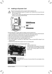
... damage. PCI Express x16 Slot PCI Express x1 Slot PCI Slot Follow the steps below to install an expansion card: •• Make sure the motherboard supports the expansion card. If necessary, go to BIOS Setup to the chassis back panel with the slot, and press down on the top edge...
... damage. PCI Express x16 Slot PCI Express x1 Slot PCI Slot Follow the steps below to install an expansion card: •• Make sure the motherboard supports the expansion card. If necessary, go to BIOS Setup to the chassis back panel with the slot, and press down on the top edge...

Manual
Page 20
... is occurring No data transmission or receiving is occurring Center/Subwoofer Speaker Out Jack (Orange) Use this audio jack for the Onboard Graphics: This motherboard provides three video output ports: D-Sub, DVI-D, and HDMI. Mic In Jack (Pink) The default Mic in jack. RJ-45 LAN Port...When removing the cable connected to the instructions on setting up to an external audio system that your device and then remove it from the motherboard. •• When removing the cable, pull it side to side to perform different functions via the audio software. Rear Speaker Out Jack...
... is occurring No data transmission or receiving is occurring Center/Subwoofer Speaker Out Jack (Orange) Use this audio jack for the Onboard Graphics: This motherboard provides three video output ports: D-Sub, DVI-D, and HDMI. Mic In Jack (Pink) The default Mic in jack. RJ-45 LAN Port...When removing the cable connected to the instructions on setting up to an external audio system that your device and then remove it from the motherboard. •• When removing the cable, pull it side to side to perform different functions via the audio software. Rear Speaker Out Jack...

Manual
Page 21
... and your devices are compliant with the connectors you wish to connect. •• Before installing the devices, be sure to the connector on the motherboard. - 21 - 1-7 Internal Connectors 1 14 8 2 4 6 3 7 5 7 9 12 13 10 11 1) ATX_12V_2X4 2) ATX 3) CPU_FAN 4) SYS_FAN 5) BAT 6) SATA3 0/1 7) SATA2 2/3/4/5 8) F_PANEL 9) F_AUDIO 10) F_USB1/F_USB2 11) F_USB30 12) COM 13...
... and your devices are compliant with the connectors you wish to connect. •• Before installing the devices, be sure to the connector on the motherboard. - 21 - 1-7 Internal Connectors 1 14 8 2 4 6 3 7 5 7 9 12 13 10 11 1) ATX_12V_2X4 2) ATX 3) CPU_FAN 4) SYS_FAN 5) BAT 6) SATA3 0/1 7) SATA2 2/3/4/5 8) F_PANEL 9) F_AUDIO 10) F_USB1/F_USB2 11) F_USB30 12) COM 13...

Manual
Page 22
... power connector mainly supplies power to the power connector in the correct orientation. If a power supply is turned off and all the components on the motherboard. Definition 1 GND (Only for 2x4-pin 12V) 2 GND (Only for 2x4-pin 12V) 3 GND 4 GND 5 +12V (Only for 2x4-pin 12V) 6 +12V (Only for 2x4...
... power connector mainly supplies power to the power connector in the correct orientation. If a power supply is turned off and all the components on the motherboard. Definition 1 GND (Only for 2x4-pin 12V) 2 GND (Only for 2x4-pin 12V) 3 GND 4 GND 5 +12V (Only for 2x4-pin 12V) 6 +12V (Only for 2x4...

Manual
Page 23
... battery: 1. Most fan headers possess a foolproof insertion design. Danger of the battery holder, making them short for one . Do not place a jumper cap on this motherboard are not configuration jumper blocks. 3/4) CPU_FAN/SYS_FAN (Fan Headers) All fan headers on the headers. 5) BAT (Battery) The battery provides power to keep the values...
... battery: 1. Most fan headers possess a foolproof insertion design. Danger of the battery holder, making them short for one . Do not place a jumper cap on this motherboard are not configuration jumper blocks. 3/4) CPU_FAN/SYS_FAN (Fan Headers) All fan headers on the headers. 5) BAT (Battery) The battery provides power to keep the values...

Manual
Page 26
...No. Definition Pin No. For information about connecting the front panel audio module that has separated connectors on each wire instead of the motherboard header. Each USB header can provide two USB ports via the audio software in Chapter 5, "Configuring 2/4/5.1/7.1-Channel Audio." •• ... to the instructions on both of the front and back panel audio connections simultaneously. Incorrect connection between the module connector and the motherboard header will be sure to turn off your chassis provides an AC'97 front panel audio module, refer to USB 2.0/1.1 specification...
...No. Definition Pin No. For information about connecting the front panel audio module that has separated connectors on each wire instead of the motherboard header. Each USB header can provide two USB ports via the audio software in Chapter 5, "Configuring 2/4/5.1/7.1-Channel Audio." •• ... to the instructions on both of the front and back panel audio connections simultaneously. Incorrect connection between the module connector and the motherboard header will be sure to turn off your chassis provides an AC'97 front panel audio module, refer to USB 2.0/1.1 specification...
Manual
Page 29
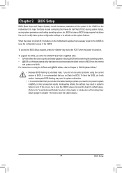
...not alter the default settings (unless you need to) to prevent system instability or other unexpected results. To upgrade the BIOS, use either the GIGABYTE Q-Flash or @BIOS utility. •• Q-Flash allows the user to quickly and easily upgrade or back up BIOS without entering the operating... and @BIOS utilities, refer to Chapter 4, "BIOS Update Utilities." •• Because BIOS flashing is turned off, the battery on the motherboard. Its major functions include conducting the Power-On Self-Test (POST) during the POST when the power is turned on using the current version of...
...not alter the default settings (unless you need to) to prevent system instability or other unexpected results. To upgrade the BIOS, use either the GIGABYTE Q-Flash or @BIOS utility. •• Q-Flash allows the user to quickly and easily upgrade or back up BIOS without entering the operating... and @BIOS utilities, refer to Chapter 4, "BIOS Update Utilities." •• Because BIOS flashing is turned off, the battery on the motherboard. Its major functions include conducting the Power-On Self-Test (POST) during the POST when the power is turned on using the current version of...

Manual
Page 31
The 3D BIOS Screen (Default) On GIGABYTE's uniquely designed 3D BIOS screen, you can click the function menu icons at the bottom of the screen or press to switch to the main ... not connected, the 3D BIOS screen will automatically switch to the main menu of the BIOS Setup program, press arrow keys to move through the motherboard image and click to configure CPU/memory frequency, memory timings, and voltage settings. For more detailed configuration items, you can use your mouse arrow over...
The 3D BIOS Screen (Default) On GIGABYTE's uniquely designed 3D BIOS screen, you can click the function menu icons at the bottom of the screen or press to switch to the main ... not connected, the 3D BIOS screen will automatically switch to the main menu of the BIOS Setup program, press arrow keys to move through the motherboard image and click to configure CPU/memory frequency, memory timings, and voltage settings. For more detailed configuration items, you can use your mouse arrow over...


